Setting lathe tool height using a prism

Home Model Engine Machinist Forum

Help Support Home Model Engine Machinist Forum:

This site may earn a commission from merchant affiliate links, including eBay, Amazon, and others.
Had a call from my mate later this morning saying he had found another box of prisms, this chap seems to have good supplies of everything I have ever needed (he used to strip down thousands of military black boxes and parts containers for a scrapyard on the understanding he can keep whatever he fancied).

Anyway, after a five minute drive, I was rummaging in his boxes and came away with these. He is one of my old school, take whatever I want for nothing giving that he has first refusal at what I am getting rid of, it is called backscratching.
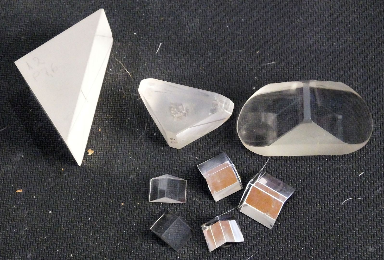
DSCF6219_zpsr4a1ttpb.jpg


The smallest ones are about 10mm square on the viewing face, just right for what I want.

Just to give you some idea about what I have been going on about, here is a 3rd edition Crap-o-Cad drawing showing my basic working sketch.
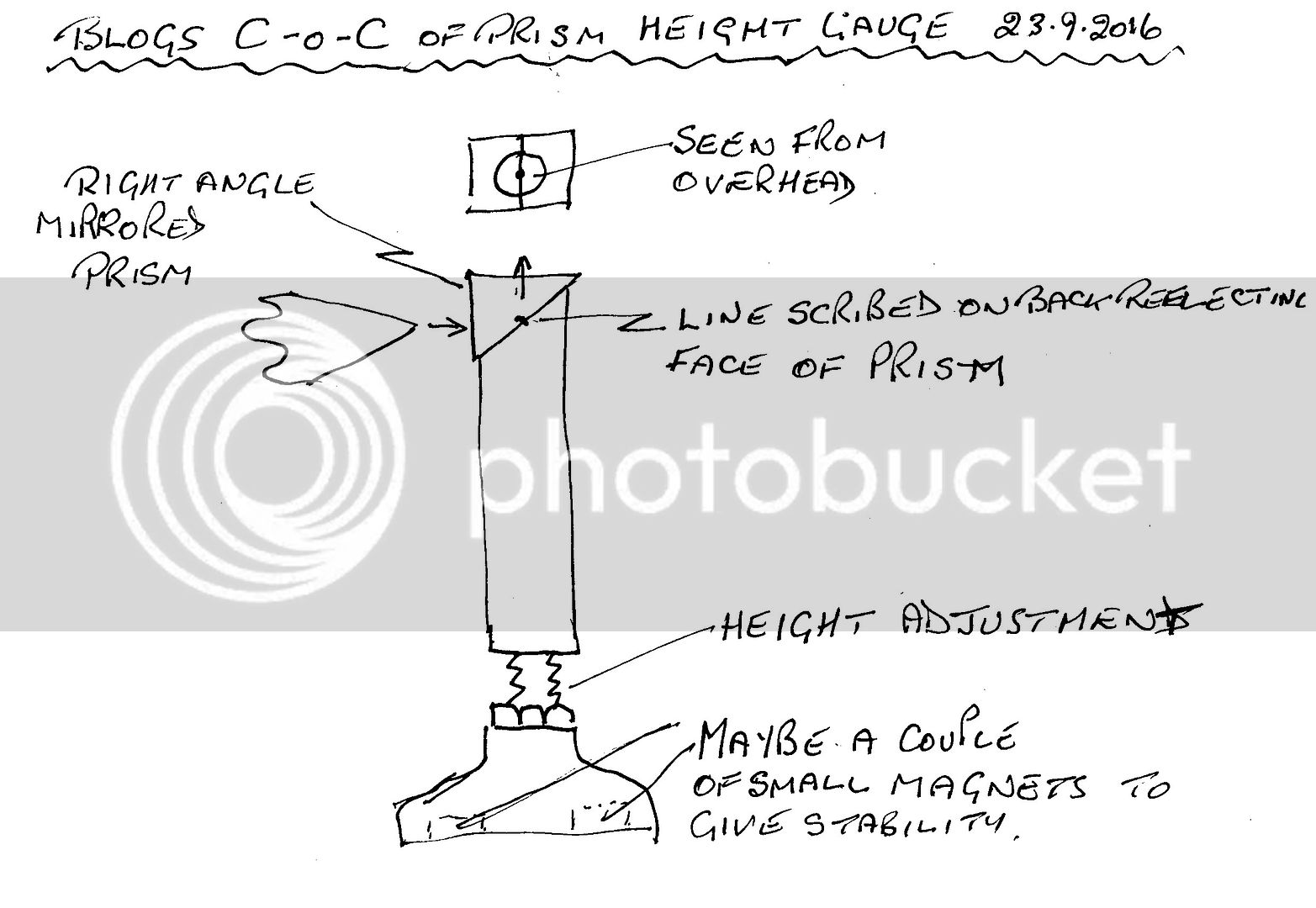
scan0001_zpsftrjzyh8.jpg


So I should now be able to start experimenting.

John
 
Timely post. I had something important chucked up I didn't want to disturb & was putting in various hand ground boring bar inserts which of course were different center heights. I did not have a good way of swinging the bit around to the tailstock center to verify height & that way. And just the way the part worked out, could not register center off the OD either. I tried putting a laser pointer in the tailstock chuck. The one I have is completely useless for that. The dot is to way too large even trying to split the dot difference & who knows how concentric the housing can is.

I remembered jotting down an accurate center height note (relative to lathe bed flats) once upon a time & found the dimension. So I used a 234 plus gauge bocks to mimic the height & then registered zero off the stack with my mag base & test indicator. Then I just transferred that over to the lathe setup & jacked the tool post height accordingly until the tool tip registered same zero on DTI. I don't know if it was bang on but was close enough to dodge the bullet. Maybe what I should do is machine a length 'standard' & save me replicating the stack-up.

Before knocking down the setup I should have checked this against the vertical ruler trick. Is there any reason that dragging the DTI ball across the tool tip highest point would not be accurate? Anyway, a jig of some sort is a good idea.

9-23-2016 0000.jpg


9-23-2016 0001.jpg
 
P,

That is the reason I need to do it without touching the tip.

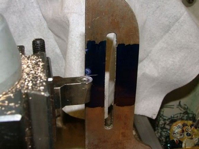
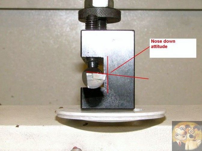
As I explained earlier, on my CCMT mounted boring bars, to allow the largest boring bar to fit into a hole, the bar has two flat sides so that it sits correct in the toolpost and the tip is mounted in a downwards tip configuration, so anything checking the exact tip has to be visual instead of mechanical, as the point of contact is just too small to touch with anything before it falls off the extreme tip, or climbs higher if you try to measure a little up the slope. I have been getting away with a scribed line for many years, but due to physical reasons it is difficult for me to see when that tip is now splitting a scribed line.

These piccies might explain what I am on about

The scribed line height was found by the long winded method of gradually bringing a tool tip up to perfect height by shaving across the end of a bar, then that height adjusted tool was used to scribe a line across my upstand. Then when I need to bring a new tool to height, the tip is adjusted until the very tip edge 'splits' the line, which should give an accuracy at within 0.001".

09_zpsj1yzbjlc.jpg


This is what I am on about when I say the tip has a downwards slope on it.

10_zpsbuytfqyw.jpg


By using this method I have been able to get very accurate results up until now with any configuration of tip. But now I can't get comfortably into the position to eyeball this splitting of the line. So as we get older and less flexible we have to come up with new ideas or recall old ideas to solve the problem. If I hadn't done things like this and mods to my machines, I would have had to give up model engineering many years ago.
Maladies have to be overcome or catered for to keep going if they are starting to affect you.

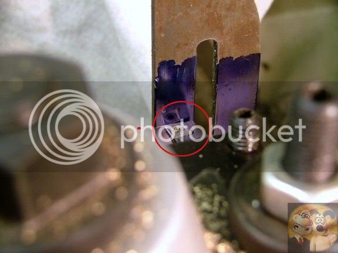
This is bringing the tip down boring bar tip to correct height.
11_zpsywa7lbgq.jpg


I now hope that this explains why I am going down the route I am. I will still be splitting the line, but viewing the alignment from the top, a much easier position for me to get into.

John
 
Last edited:
Hi John
I would make a holder for the prism and attach a fine wire (hair) to the front of it, rather than a scribed line on the mirror face. There is a chance the mirror will chip and not leave a sharp line.
Another thought is to attach a lens and eyepiece so you can get a nice close up view, you can get eyepieces with graticules.
I have made quite a few lens and mirror holders for our optical shop over the years, good luck with you project I look forward to seeing the finished item :thumbup:

Paul
 
Paul,

The actual prism will be mounted down into the top of the holder for protection. I only showed it that way so people could understand the principle.

I have actually made a fine line across the back of a mirrored prism before, with no problems. I used the razor sharp carbide tip of my height gauge. In fact, it was so fine, I had to do a couple more strokes to make it stand out a little better, but if I do have problems, I will certainly consider your method, but I think I would be a little phased by it because the line won't be be on the mirror, but on one of the sighting faces. I will suck it and see.

I already have magnifying eyepieces in my 'junk' boxes, so if there are any sighting problems it will be easy to fit one and try it.

The first one that I will make will be a trial as the prisms are second hand, and a couple have tiny chips on their edges (they don't affect the sight line). The final ones will be made with the new ones I have ordered from China. I want the final version to last me until I can't use it any more.

Many thanks indeed for your suggestions.


John
 
Gotcha John. And your picture clearly demonstrates why my test indicator method isn't reliable at all (unless the tool is pointing up). The DTI ball measurement is only meaningful with the ball perfectly centered on the tool tip plane. But I have no way of positioning it that way other than eyeballing. If the ball is located in any other position, the tool tip is still in contact with DTI ball & giving a reading, but its irrelevant because its not tangent to the ball bottom.

I think you are saying the scratch method works great, you just want better magnification optics & view perspective. Look forward to what you come up with.

9-24-2016 0000.jpg
 
It is a bit of an enigma Peter, just one of those problems that MIGHT have lots of different solutions. Finding the right one for personal use is the main obstacle.
I could easily design and make something using one of the small prismatic periscopes I have, it would be ideal, FOR ME, but for no-one else as they could most probably never be able to find exactly what I have in my 'junk' boxes.

Here is a chap that has had the same sort of problem as myself, negatively raked tip on boring bars (so I am not alone), and he has come up with an easier solution than I have. Same sort of principle but just using a bit of perspex and a mirror. Unfortunately not the solution I am looking for as when aligning two lines AND the tip, to me, error could easily occur, but it works for him.

http://www.practicalmachinist.com/v...ing-bar-tool-height-lathe-220461/#post1521479

It is like searching for the perfect mouse trap, but I have even found one of those, to MY satisfaction.

My partner has a cat that keeps bringing home live mice, sometimes two in one night, and it is a major thing in her household, she won't even harm a moth that is fluttering around at 2 in the morning, or a spider climbing up a wall, it has to be caught and released outside, unharmed.
I searched all over the place until I found a humane trap that works, and it works great. Just a bit of chocolate bar inside and within a few hours, mouse or mouses is/are ready to be released totally unharmed, except for a bit of ruffled fur. A couple of these solved all our feline induced rodent problems. Just check the traps a couple of times a day just in case the feline has brought in any we don't know about. Usually the cat is sitting next to the 'sprung' trap, expecting us to let her have her prey to play with. Sorry cat, no can do, her indoors would be even less humane to me.

http://www.ebay.co.uk/itm/REUSABLE-...484783?hash=item58ab34c6ef:g:w4QAAMXQydtTPb~P

There should be a solution for almost all our problems, it is finding the right one for you (and other people with the same problem), and that is another solution that needs solving along the way.
Getting it easy to make so that anyone who wants one can make one for themselves.

John
 
Last edited:
Looks great :thumbup:
Simple to use and looks like it will works ever time

Dave
It is like searching for the perfect mouse trap, but I have even found one of those, to MY satisfaction.

My partner has a cat that keeps bringing home live mice,

http://www.ebay.co.uk/itm/REUSABLE-...484783?hash=item58ab34c6ef:g:w4QAAMXQydtTPb~P

There should be a solution for almost all our problems, it is finding the right one for you (and other people with the same problem), and that is another solution that needs solving along the way.
Getting it easy to make so that anyone who wants one can make one for themselves.

John
 
I have already started to make one, not quite as shown in the sketch, but due to other things happening around me, it will be weekend before I can carry on.

I only want to do one posting to cover the whole lot, so it will take some time to write it up and get the pictures corrected (I have to take at least a dozen shots of each operation), not the cameras' fault, but mine.

John
 

Latest posts

Back
Top