mariolucchini
Member
- Joined
- Sep 15, 2009
- Messages
- 19
- Reaction score
- 0
After much looking the PMR lathe, both the wonderful builds here in this forum and in other web sites, I decided to take the plunge and scratchbuild a freelance version of it...
As I have no chance of getting the PMR castings, I started making a scale set of drawings in Autocad and began using some very unusual series of materials....
Most parts of the lathe's body are made from different thicknesses of acrylic plate which is more than sturdy for this project....
I made the drawings of certain parts so as to simulate the "cast look" found in those old lathes....I'm using fillets and chamfers to achieve that goal....
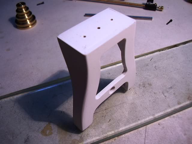
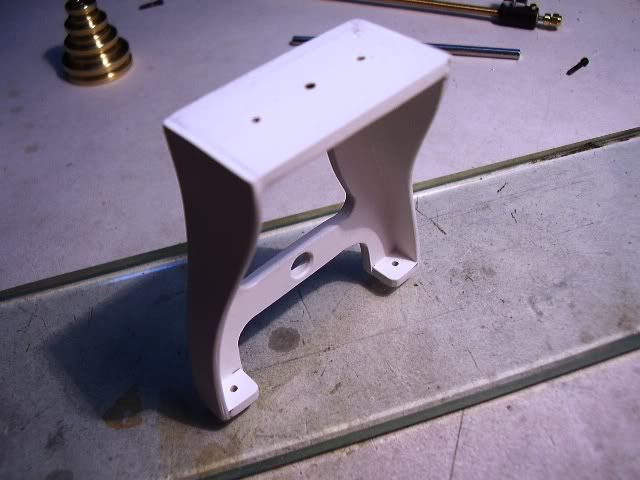
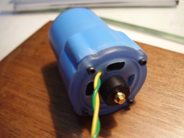
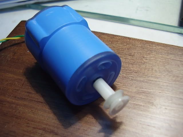
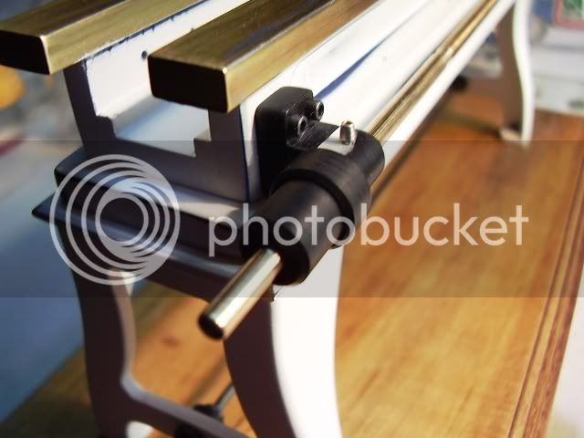
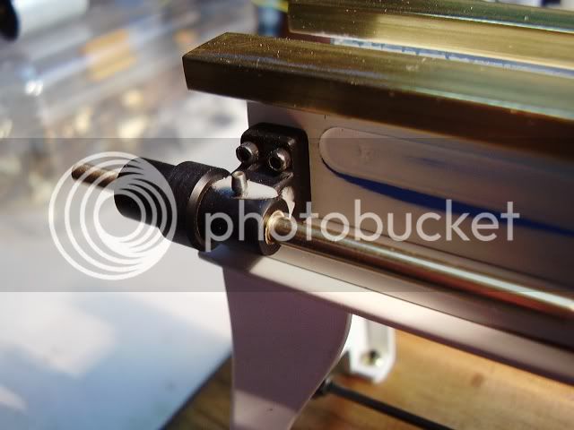
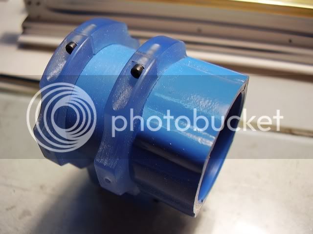
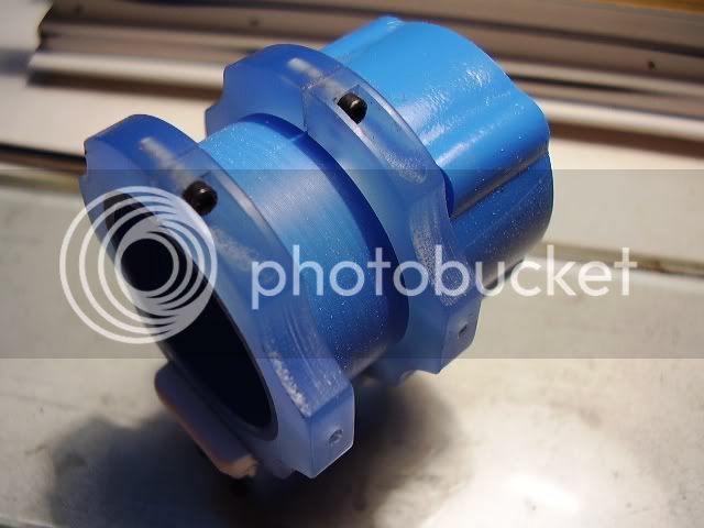
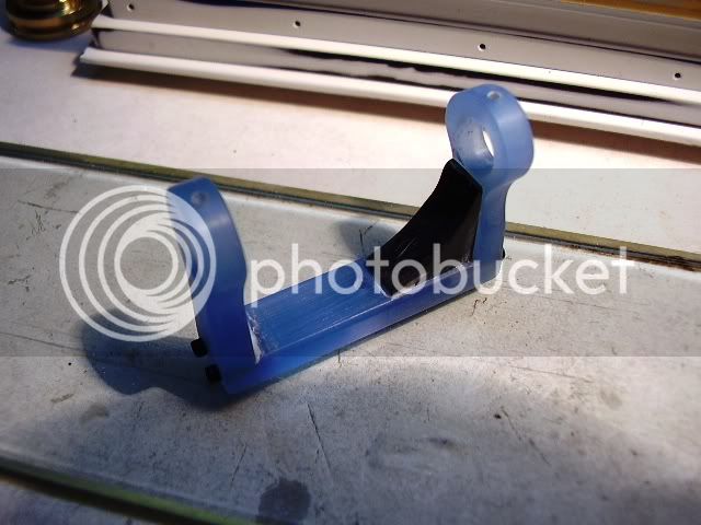
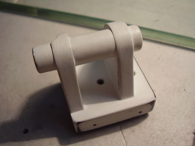
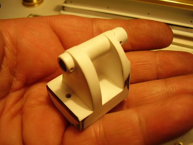
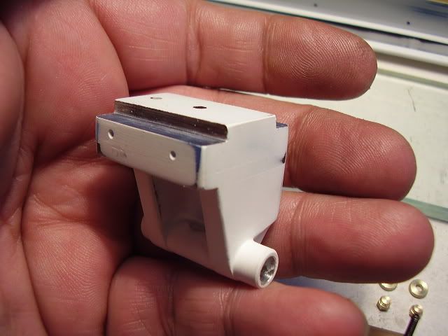
The tailstock body with the first primer coats... the whole tailstock body is made from acrylic plate, except the barrel for the spindle which was turned from aluminium...
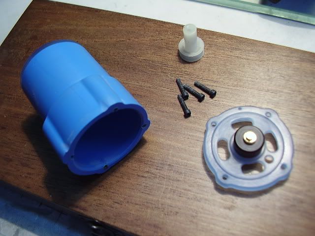
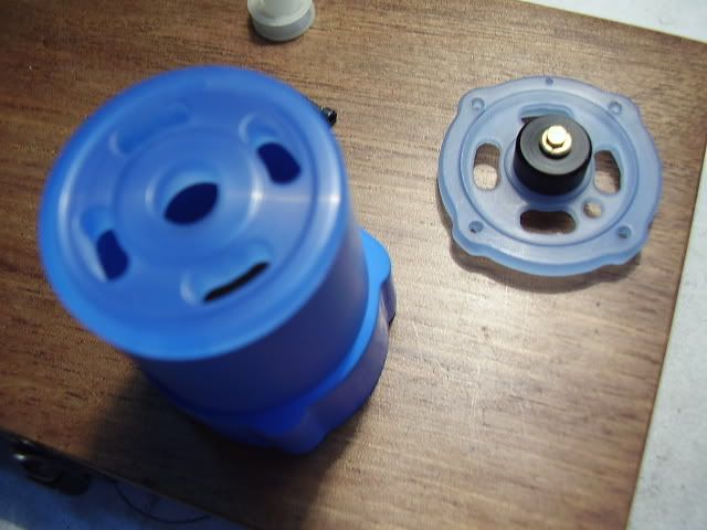
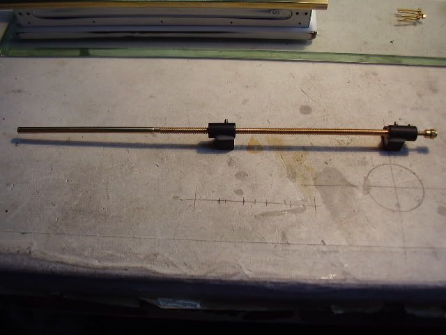
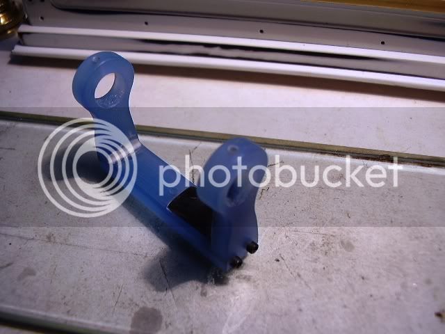
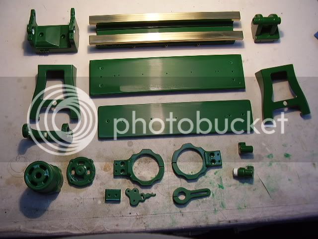
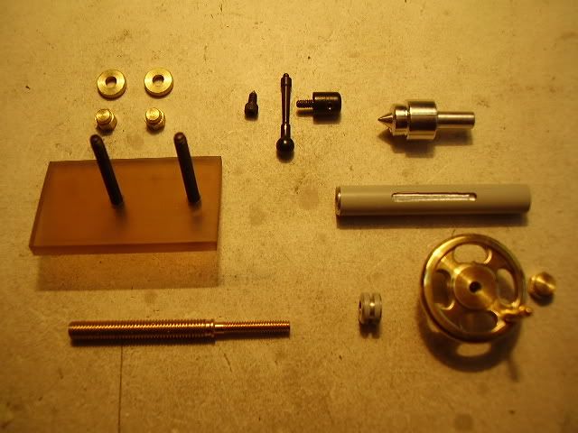
The tailstock mechanism.......
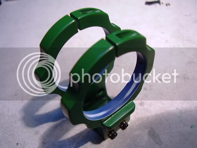
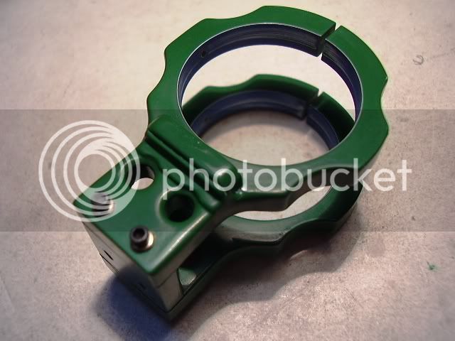
From left to right, first row, the fixing plate's nuts and washers, the locating threaded pin, the lever, the spindle guide and locking device and a center....
Second row, the fixing plate and the spindle body...(Threaded inside 3 mm left hand)...
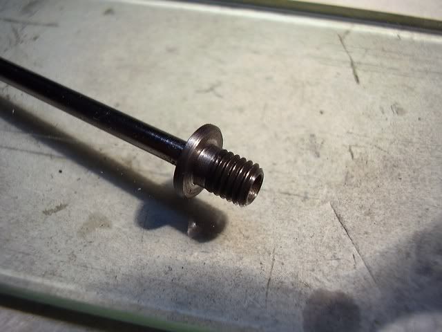
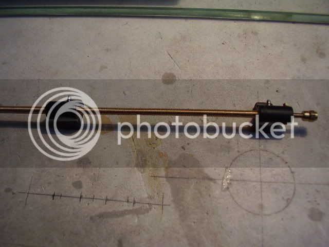
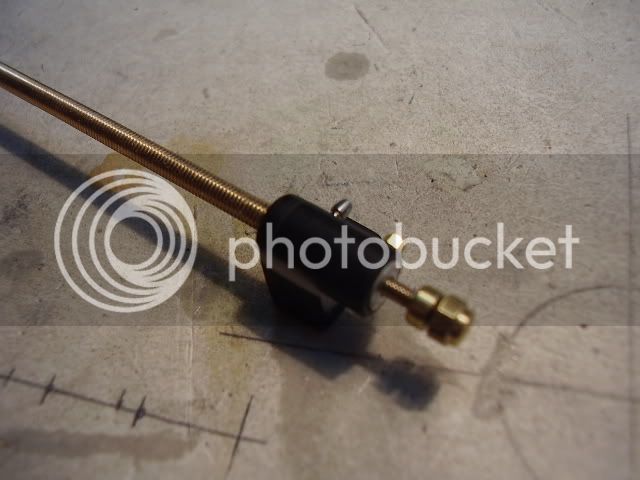
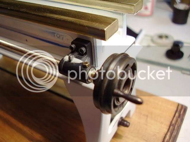
Third row, the spindle's threaded mainscrew, threaded 3 mm left hand and 2 mm right hand to receive the handwheel, the fixing collar, and finally the handwheel turned & milled from brass, with the fixing nut....
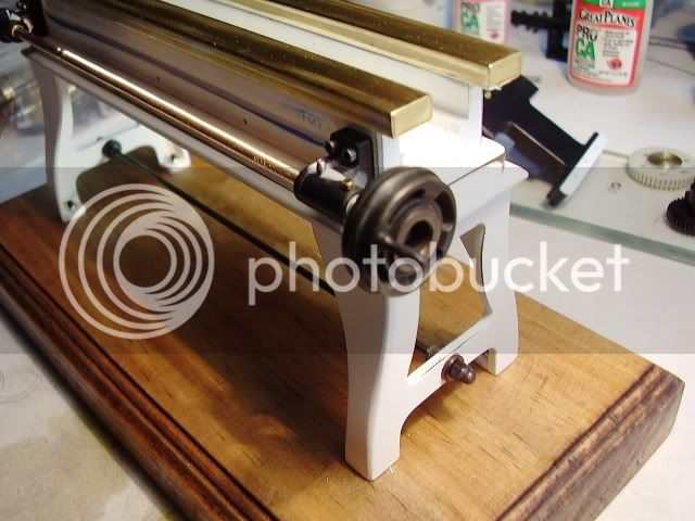
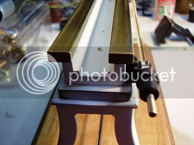
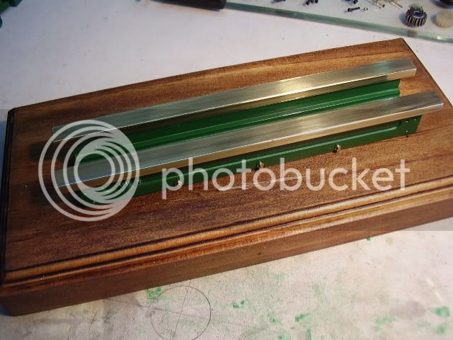
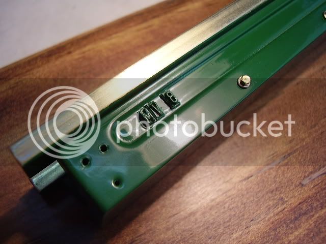
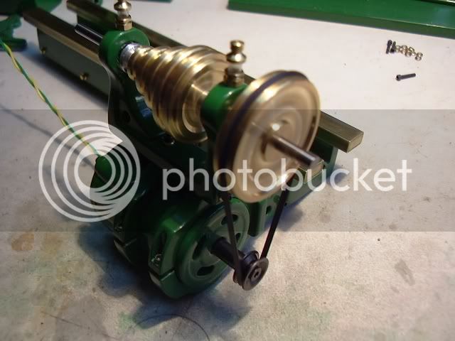
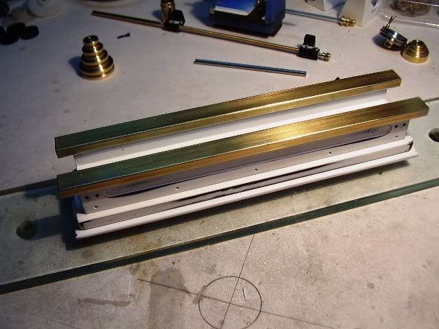
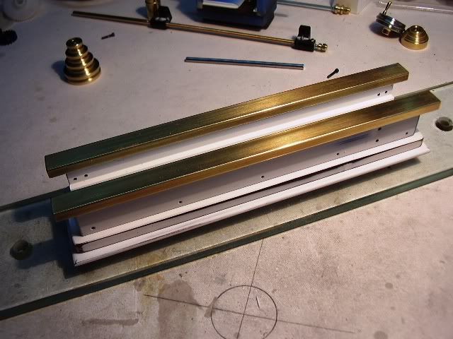
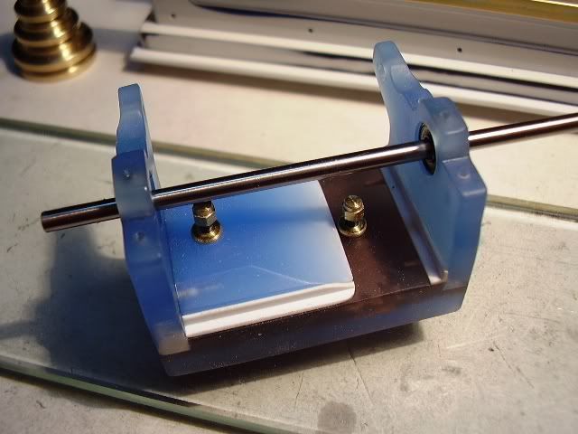
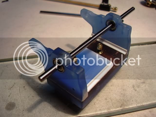
The lathe's bed made in heavy acrylic plate, the bed ways from K&S rectangular brass tubing....
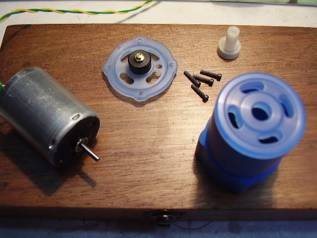
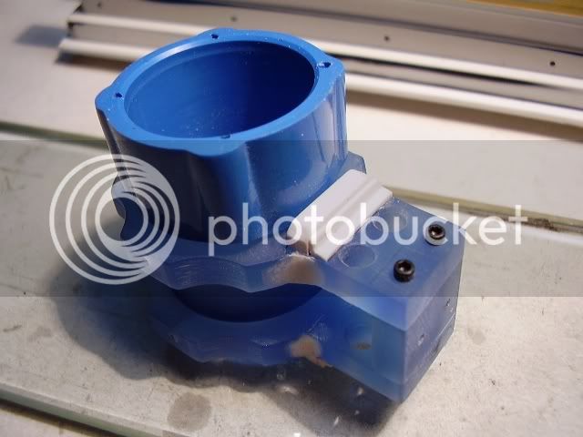
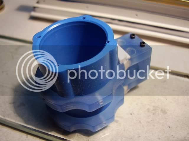
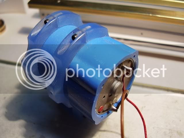
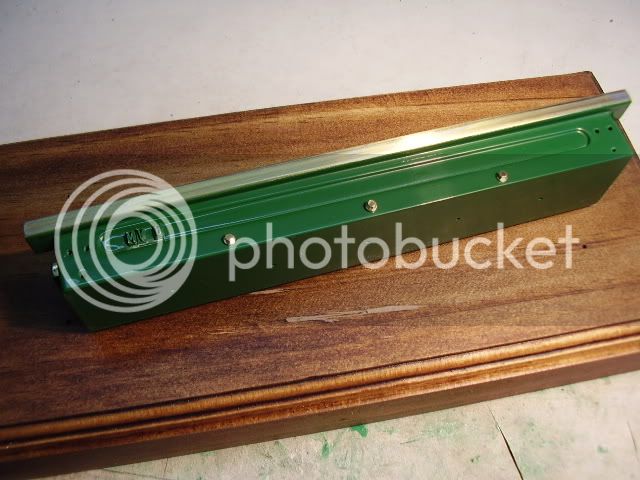
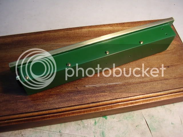
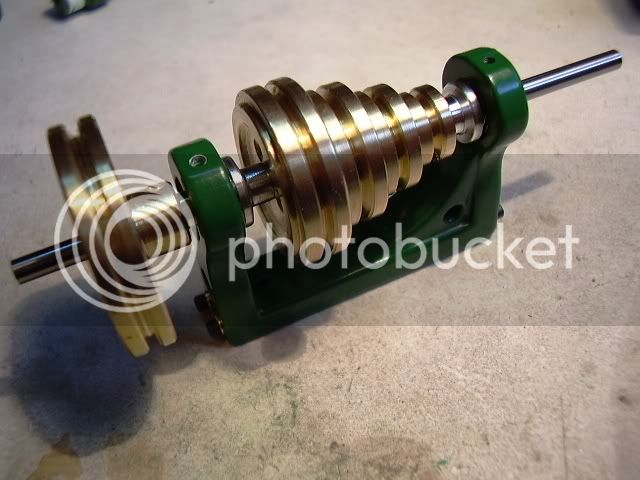
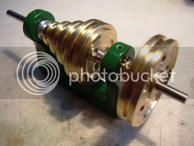
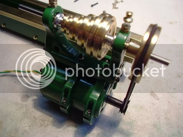
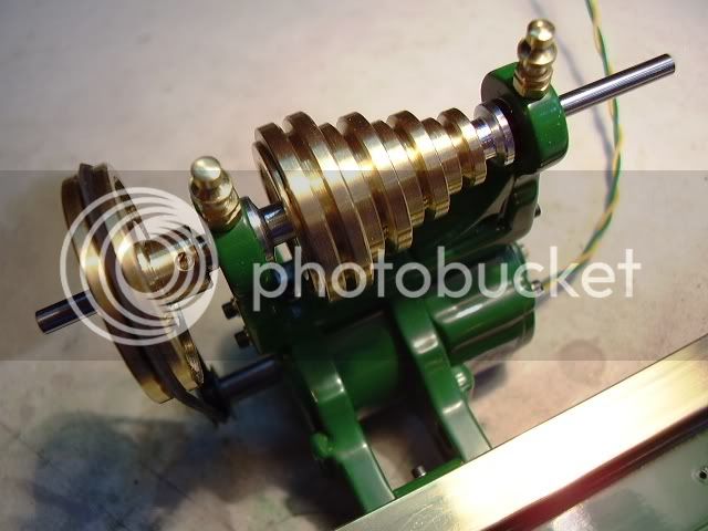
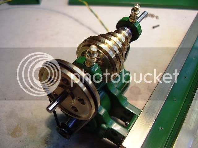
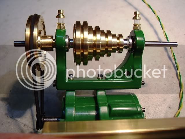
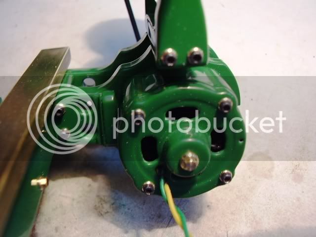
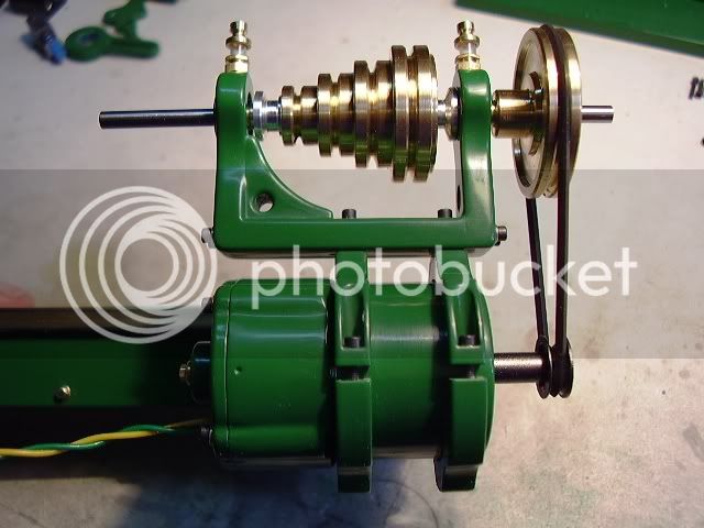
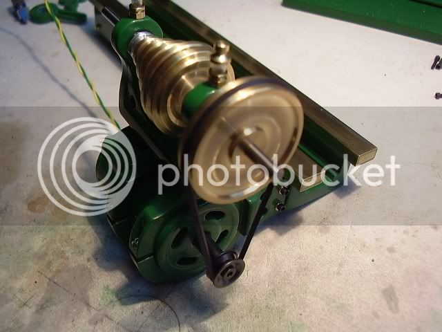
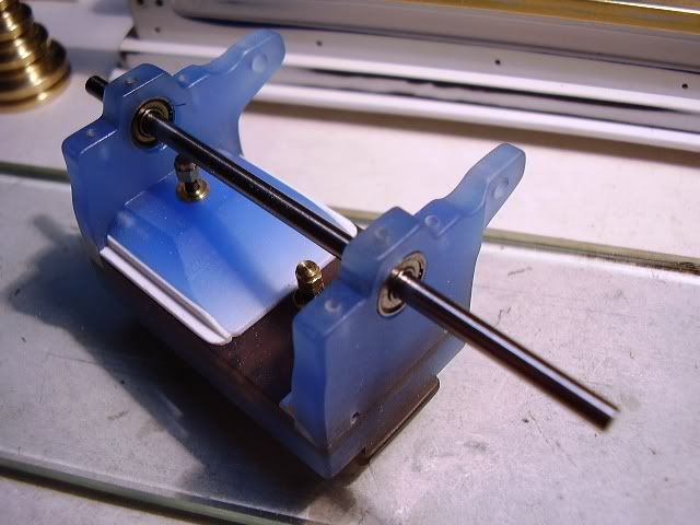
The headstock "casting" in the raw, you can see the acrylic material here....the headstock's axle is 3 mm diameter drill rod and it rotates in ball bearings taken from discarded PC fans.....3mm inside dia., 8 mm outside dia. and 4 mm thick....
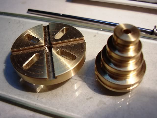
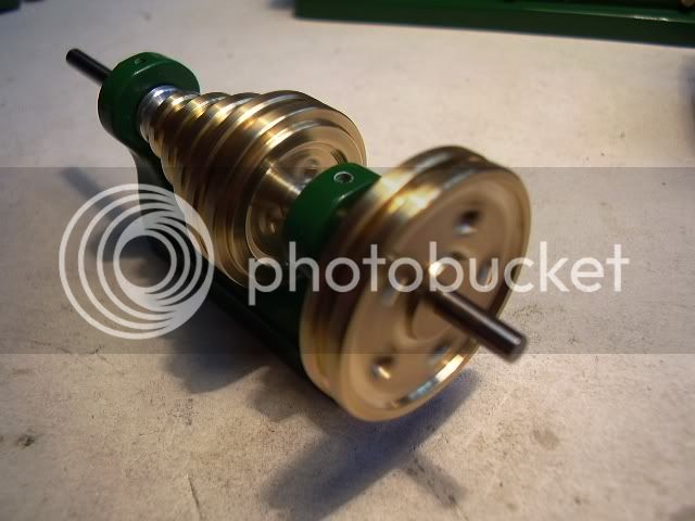
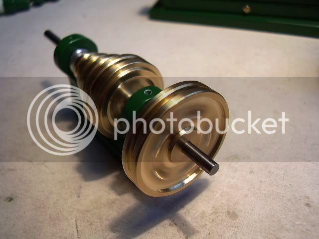
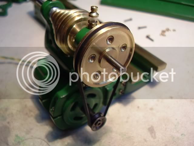
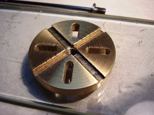
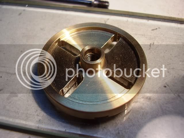
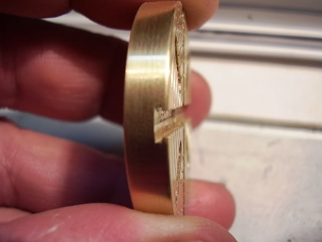
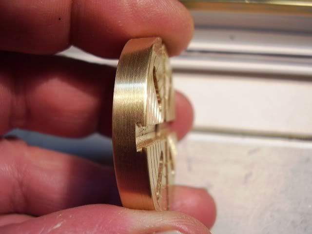
And to finish this already long and boring post, the faceplate, turned and milled from brass.....I did some delicate grinding on a Dremel mini-saw to make the "T nut" channels, it came out fine for my tastes, hee, hee... :big:.......
To be continued....
Mario
As I have no chance of getting the PMR castings, I started making a scale set of drawings in Autocad and began using some very unusual series of materials....
Most parts of the lathe's body are made from different thicknesses of acrylic plate which is more than sturdy for this project....
I made the drawings of certain parts so as to simulate the "cast look" found in those old lathes....I'm using fillets and chamfers to achieve that goal....
The tailstock body with the first primer coats... the whole tailstock body is made from acrylic plate, except the barrel for the spindle which was turned from aluminium...
The tailstock mechanism.......
From left to right, first row, the fixing plate's nuts and washers, the locating threaded pin, the lever, the spindle guide and locking device and a center....
Second row, the fixing plate and the spindle body...(Threaded inside 3 mm left hand)...
Third row, the spindle's threaded mainscrew, threaded 3 mm left hand and 2 mm right hand to receive the handwheel, the fixing collar, and finally the handwheel turned & milled from brass, with the fixing nut....
The lathe's bed made in heavy acrylic plate, the bed ways from K&S rectangular brass tubing....
The headstock "casting" in the raw, you can see the acrylic material here....the headstock's axle is 3 mm diameter drill rod and it rotates in ball bearings taken from discarded PC fans.....3mm inside dia., 8 mm outside dia. and 4 mm thick....
And to finish this already long and boring post, the faceplate, turned and milled from brass.....I did some delicate grinding on a Dremel mini-saw to make the "T nut" channels, it came out fine for my tastes, hee, hee... :big:.......
To be continued....
Mario


![DreamPlan Home Design and Landscaping Software Free for Windows [PC Download]](https://m.media-amazon.com/images/I/51kvZH2dVLL._SL500_.jpg)