You are using an out of date browser. It may not display this or other websites correctly.
You should upgrade or use an alternative browser.
You should upgrade or use an alternative browser.
Rotary motion to reversible linear motion
- Thread starter Brian Rupnow
- Start date

Help Support Home Model Engine Machinist Forum:
This site may earn a commission from merchant affiliate
links, including eBay, Amazon, and others.
Maybe.
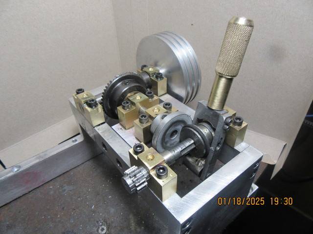
So, getting very close to a working module. The 1/8" cross section o-ring on the final drive shaft is going to have to be changed, as the action is rather intermittent right now, (it slips) but it does work. The simplest change would be to go to a 3/16" cross section o-ring, and tomorrow I will try that. It is a very interesting little project. I won't build the transfer cart and the rails until I get this drive working okay.---Brian

Hi Brian, Is the O-ring in a Vee groove? A Vee is the better shape for developing friction and preventing slippage - I think?
What material O-ring are you using? Some elastomers are a lower friction than plain or nitrile rubber... Viton is a lower friction I think? - Better to avoid those? - I use Nitrile, because that's what I happened to have. I think it was intended for a domestic water seal - use with a plastic fitting of some sort onto Bathroom ceramic? It didn't like any oil on the drive surfaces, but liked a little roughing of the disc surface from the Knurling tool. It gave the steel-rubber interface a "tread". - Works with very low contact pressure on my model, but yours is on a proper machine drive , many orders of magnitude greater than my steam boat drive.
K2
The o-ring is nitrile rubber setting in a v-groove. The face of the contact wheel has been sandblasted to give it a uniform rough surface.
Today was a good day for laying around the house doing nothing. Finally, about 3:00 I summoned enough energy to come down to my shop and start the fabrication and assembly of the long frame that the carriage rolls back and forth on. No drama--everything went as I had hoped (the rack is just setting there, not bolted down). Lookin' good so far. Tomorrow I will make the four stands that tie the long frame to the frame with the gears on it. I ordered a box of 50 o-rings from McMaster-Carr today---I only need one, so I will end up with 49 spare o-rings.


Last edited by a moderator:

$49.95
$55.99
DjuiinoStar Hot Air Stirling Engine Assembly Kit: Spend 30 Minutes to Build Your Own Stirling Engine
djuiinostar
![DreamPlan Home Design and Landscaping Software Free for Windows [PC Download]](https://m.media-amazon.com/images/I/51kvZH2dVLL._SL500_.jpg)
$0.00
DreamPlan Home Design and Landscaping Software Free for Windows [PC Download]
Amazon.com Services LLC

$45.99
Sunnytech Mini Hot Air Stirling Engine Motor Model Educational Toy Kits Electricity HA001
stirlingtechonline

$99.99
AHS Outdoor Wood Boiler Yearly Maintenance Kit with Water Treatment - ProTech 300 & Test Kit
Alternative Heating & Supplies

$171.00
$190.00
Genmitsu CNC 3018-PRO Router Kit GRBL Control 3 Axis Plastic Acrylic PCB PVC Wood Carving Milling Engraving Machine, XYZ Working Area 300x180x45mm
SainSmart Official

$37.38
$49.99
Becker CAD 12 3D - professional CAD software for 2D + 3D design and modelling - for 3 PCs - 100% compatible with AutoCAD
momox Shop

$599.00
$649.00
FoxAlien Masuter Pro CNC Router Machine, Upgraded 3-Axis Engraving All-Metal Milling Machine for Wood Acrylic MDF Nylon Carving Cutting
FoxAlien Official

$26.89
$34.99
Peachtree Woodworking Supply Bowl Sander Tool Kit w/Dual Bearing Head & Hardwood Handle, 42 Pieces Wood Sander Set, 2 Hook & Loop Sanding Disc Sandpaper Assortment, 1/4 Mandrel Bowl Sander
Peachtree Woodworking Supply Inc

$19.15
$29.95
Competition Engine Building: Advanced Engine Design and Assembly Techniques (Pro Series)
MBC Inc.
Brian,
I am sure that you will find a use for them, in some project yet to hit the paper, The carriage looks good.
Cheers
Andrew
I am sure that you will find a use for them, in some project yet to hit the paper, The carriage looks good.
Cheers
Andrew
I would have thought that a polished surface would have been preferable...The o-ring is nitrile rubber setting in a v-groove. The face of the contact wheel has been sandblasted to give it a uniform rough surface.
as a rough surface should lead to rapid O-ring wear and slippage due to the drop in pressure, imo.
- Joined
- Feb 26, 2020
- Messages
- 743
- Reaction score
- 464
Will the O-rings polish the disc over time? The PU rubber cords (not sure if that is the right word), to create small drive belts have slightly rough texture, they can be welded with a hot knife.I would have thought that a polished surface would have been preferable...
as a rough surface should lead to rapid O-ring wear and slippage due to the drop in pressure, imo.
Assuming the gearbox is not used on a regular basis for many hours, it is probably good enough to have 49 replacements
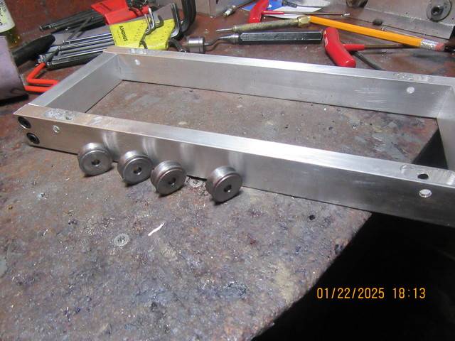
Today was wheel day. If I've lived right, the four v-groove wheels will fit into the pockets milled in the frame they are leaning against. As far as the rubber o-ring is concerned, if it is a bit too large in diameter I can always grind it down to the correct size. This machine will never run long enough to wear an o-ring out. (if it does, I have 49 spares).

Hi ZEPHYRIN. The elastomer of the O-ring needs to be one that has good fatigue resistance as it is constantly deforming and relaxing at the contact point. A rougher surface that "grips" will probably last longer than a surface with some slip. The slippage puts shear stress on the surface, and the elastomer consequently shreds material as a result, thus creating a more rapid failure? The gripping surface suffers for random fine higher pressure points, so compressive fatigue takes place, which does not shed material until the fatigue life is exceeded, when rapid deterioration occurs. Will it last longer? So who can guess which will fail first? - I think the shear forces on a smooth O-ring, wearing the O-ring cause a quicker failure, but it really is anyone's guess, as to actual surface roughness, slippage in the smooth surface condition, Wear, tear, and fatigue of unknown O-ring materials pressures and transmitted torques. What starts out as the better option may or may not be the better option for a long life.
I really don't know which is better!
K2
I really don't know which is better!
K2
Most (all) drive disks I’ve seen are smooth. Not textured. Snow blowers, rail doodle bugs, etc.Hi ZEPHYRIN. The elastomer of the O-ring needs to be one that has good fatigue resistance as it is constantly deforming and relaxing at the contact point. A rougher surface that "grips" will probably last longer than a surface with some slip. The slippage puts shear stress on the surface, and the elastomer consequently shreds material as a result, thus creating a more rapid failure? The gripping surface suffers for random fine higher pressure points, so compressive fatigue takes place, which does not shed material until the fatigue life is exceeded, when rapid deterioration occurs. Will it last longer? So who can guess which will fail first? - I think the shear forces on a smooth O-ring, wearing the O-ring cause a quicker failure, but it really is anyone's guess, as to actual surface roughness, slippage in the smooth surface condition, Wear, tear, and fatigue of unknown O-ring materials pressures and transmitted torques. What starts out as the better option may or may not be the better option for a long life.
I really don't know which is better!
K2
My snowblower is at least 15 years old, and I got it used, it has a smooth surface and the contact wheel have negligible wear, personally, I'd be more concerned with wear from a sandblasted surface though I doubt it will affect Brian's model either way he does it.Hi ZEPHYRIN. The elastomer of the O-ring needs to be one that has good fatigue resistance as it is constantly deforming and relaxing at the contact point. A rougher surface that "grips" will probably last longer than a surface with some slip. The slippage puts shear stress on the surface, and the elastomer consequently shreds material as a result, thus creating a more rapid failure? The gripping surface suffers for random fine higher pressure points, so compressive fatigue takes place, which does not shed material until the fatigue life is exceeded, when rapid deterioration occurs. Will it last longer? So who can guess which will fail first? - I think the shear forces on a smooth O-ring, wearing the O-ring cause a quicker failure, but it really is anyone's guess, as to actual surface roughness, slippage in the smooth surface condition, Wear, tear, and fatigue of unknown O-ring materials pressures and transmitted torques. What starts out as the better option may or may not be the better option for a long life.
I really don't know which is better!
K2
I spent most of yesterday and part of today making up the eight small pieces that hold the moveable cart to the rails (You can see four of them bolted to the inside of the cart frame) and four under the rails which will ultimately bolt to the frame with the gears on it. Nothing really exciting about these eight pieces, but they did require some very unusual set-ups.
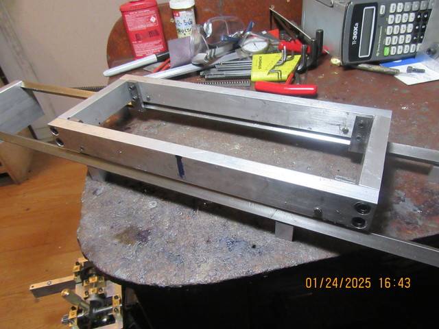

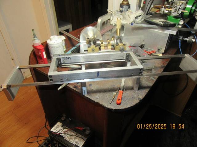
Today was a long day---all of the fabrication is finished. I have a bit of fine tuning to do, and I'm waiting for my new o-rings from McMaster-Carr. It's been a good day and a long one. ---Brian

- Joined
- Dec 31, 2010
- Messages
- 822
- Reaction score
- 220
Brian:
Maybe I missed it somewhere, but where will this contraption be used??
Is it for one of your customers?
Well done.
Maybe I missed it somewhere, but where will this contraption be used??
Is it for one of your customers?
Well done.
This Sears auto used that mechanism.
This auto was built sometime between 1905 and 1908 (exact date unknown).
It seemed to work very well.
Two cylinder horizontal opposed air cooled engine.
The sliding wheel with the rubber on it appears to only partially travel to the right in reverse I guess, but fully travels to the left (forward ?).
There was some sort of mechanism that rocked the rubberized wheel forward and back into the shiny flywheel.
.
Attachments
Last edited:
This is just a fun thing for me to build. My office is full of mechanical things that I build just because I enjoy doing it. The sliding part with the rubber o-ring on it moves equally to either side of center. After I get things tuned properly and set up one of my engines to run it, I will make a video and post it here.---Brian
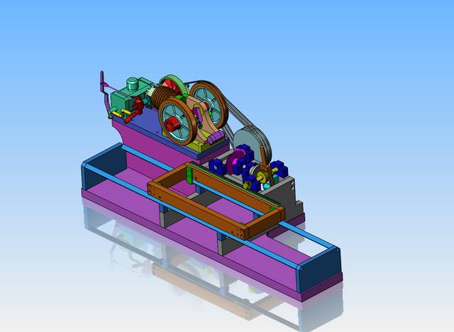
Today I finished up machining, fine tuning, and cleanup. It works amazingly well except for the drive disc sometimes slipping on the o-ring final drive. That should be fixed when my larger cross-section o-rings get here. I searched thru all of my lumber scraps and didn't find anything large enough to make a sub base out of.---And that of course brought up the question of "Should I make the sub base large enough to set one of my engines on." An air powered engine always starts and runs without much fiddling, but they are not terribly powerful. A naptha gas engine is far more powerful but require more "fiddling" with to get them to run consistently. The horizontal engine that I designed and built and was featured in the November/December 2023 issue of "The Home Shop Machinist" is about the right scale, and is powered by Naptha gas.

Last edited:
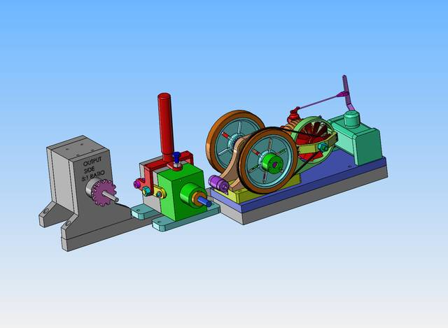
After spending half a day studying on this thing, I have decided that I need a gear reduction to slow things down, a clutch which can be disengaged to start the engine under "no load" conditions, along with my naptha gas engine. All of this stuff exists. It will simply be a matter of coming up with proper pulleys to transport the drive forces between all of the components. I will keep you in the loop as I build pulleys and sub bases to connect everything together.---Brian

Similar threads
- Replies
- 2
- Views
- 11K
- Replies
- 39
- Views
- 32K
- Replies
- 6
- Views
- 2K
J


![MeshMagic 3D Free 3D Modeling Software [Download]](https://m.media-amazon.com/images/I/B1U+p8ewjGS._SL500_.png)


