Rotary motion to reversible linear motion

Home Model Engine Machinist Forum

Help Support Home Model Engine Machinist Forum:

This site may earn a commission from merchant affiliate links, including eBay, Amazon, and others.

Brian Rupnow

Design Engineer
Project of the Month Winner
Joined
May 23, 2008
Messages
15,263
Reaction score
8,549
Location
Barrie, Ontario, Canada
It's been six weeks now since my second knee replacement surgery, and I'm dyeing from boredom. I've read about all the books I can stand, so I'm amusing myself on the computer. While trolling thru a thousand videos on the computer, I found a video of an old style sawmill with a rather unique reversing carriage drive. I have modelled the reversing drive, and think I can reproduce it in a much smaller size. I know that I have a couple of engines to get running yet, but for now I'm going to tackle something new. I can walk without a cane now, and navigate the stairs up and down to my workshop, so stick around and watch as I develop this newest model.---Brian
1735694693073.jpeg
1735694600715.jpeg
 

Attachments

  • Screenshot_31-12-2024_191414_www.youtube.com.jpeg
    Screenshot_31-12-2024_191414_www.youtube.com.jpeg
    424.4 KB
  • 1735694603043.jpeg
    1735694603043.jpeg
    266.9 KB
Last edited:
Brian.
It's good to see you thinking out side of the box again. I have seen this setup on a winch setup somewhere, can't remember where, I believe that the center of the large wheel had a slight depression so there would be no drag in the neutral position.
Will be watching.
Cheers
Andrew
 
The unpolished surface of the driven disc would seem to indicate that it is recessed.

Westbury used the same drive for his model Aveling DX roller, that too had a recess so there was no rubbing of the drive when in neutral. He had a few more refinements such as an adjustable spring to push the metal disc against the rubber wheel so you could adjust the "bite" or take up wear.
 

Attachments

  • rev box.JPG
    rev box.JPG
    100.5 KB
Last edited:
I watched the series on the friction drive drill press and I kept wondering just how much power can be transferred through a small contact patch between the friction wheel and the disk. Plus, I think that if the disk got dusty or dirty, the power transfer would get worse and worse. Slippage means the drill stops turning.

With the sawmill drive, it doesn't need that much power (relative to sawing) to traverse the carriage. Slippage isn't as big a problem.

Craig
 
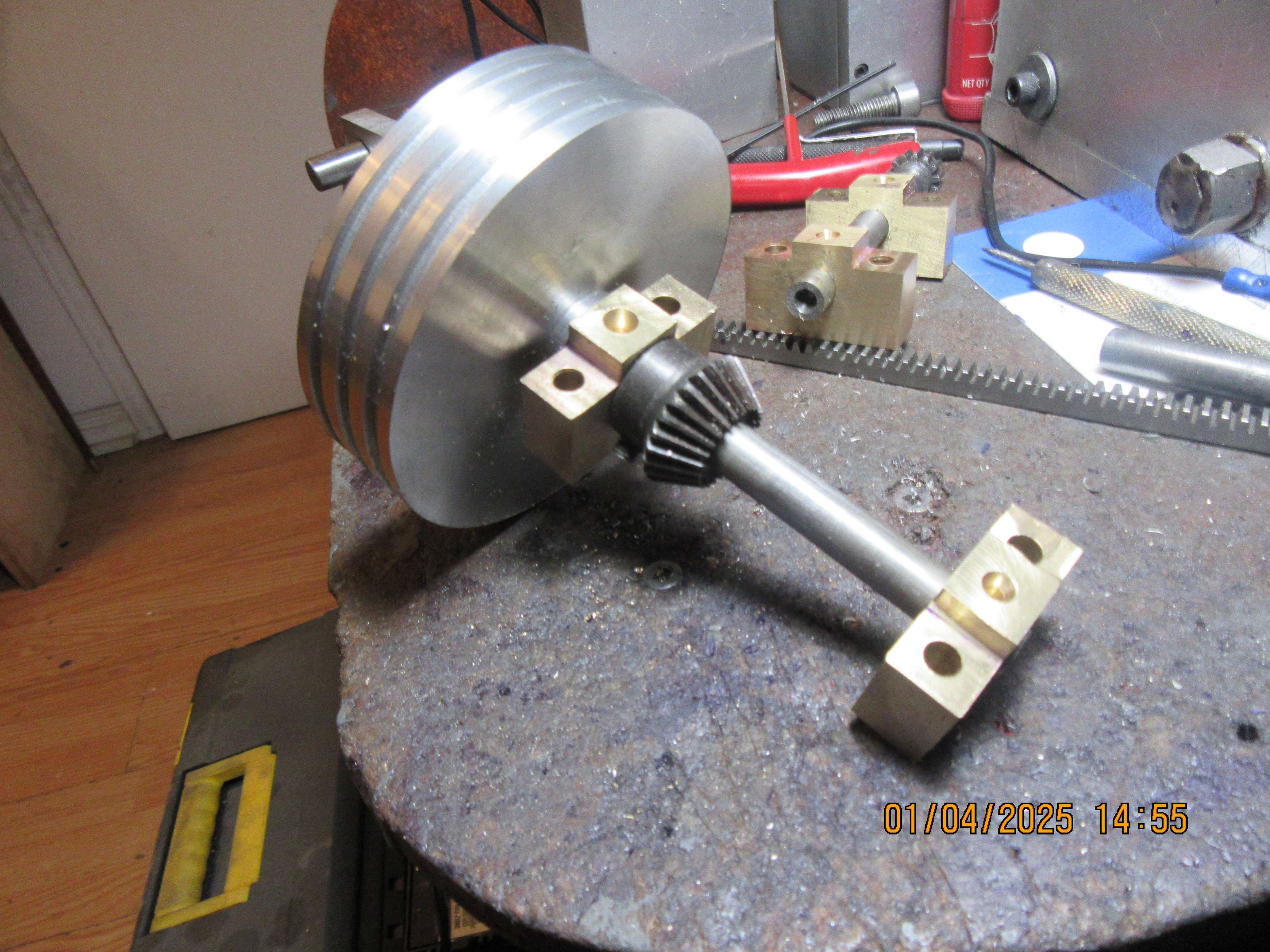
This morning I realized that the original gear I had put on the driven shaft was not a 14 tooth gear, so changed my design to show a much smaller 14 tooth gear. Then decided to be clever and machine both the gear and the shaft from one piece of cold rolled steel. This afternoon I will cut the teeth in the gear.
View attachment 1735853872666.jpeg
 
Last edited:
On a steam launch
DSCF0809.JPG
(Naval picket boat) I used a bobbin drive
DSCF0820.JPG

for neutral - ahead/astern. as shown in these pics.

DSCF0813.JPGDSCF0812.JPG
DSCF0814.JPG
There is not much movement of the servo lever so hardly any difference in these views, but perhaps you can work it out?
It didn't work at first - oil on the smooth drive disc - until I knurled the surface, which makes it about slippage free and less sensitive to oil..

This boat is full of "mechanisms":
The rudder is driven via a gear-box:
DSCF0819.JPG
For port,
DSCF0816.JPG
ahead,
DSCF0817.JPG
starboard.
DSCF0818.JPG
The gearbox doubles the mechanical advantage of the servo, reducing the battery drain and loading of the servo. But it also replicates the original design whereby the drive crossed the transom from the cable pulleys/lever on the inside (dry-side) to the outside rudder (wet-side).
A feature rarely modelled by the best of them!
The boiler, engine, drive is all non-standard for this boat. The Stuart and Turner Star engine is a 180 degree crank twin cylinder single acting engine, revving to 2000rpm.
But it cannot self-start so needs the transmission I made.
From the Bobbin mount there is a boiler condensate return feed-pump, driven from a worm/wheel and an eccentric drive to a lever, so the pump action takes over 3 turns of the bobbin, but the return (water draw) action takes only 1 turn of the bobbin. Reasoning: The pump action is working against boiler pressure, but the suction only against an inch of water pressure, So the pump action needs a good mechanical advantage, while the suction stroke needs a good velocity ratio - to be quick.
This reduces the "slowing" of the engine during the pump stroke. (A characteristic often seen on small models driving a single action pump against boiler pressure). Maybe I'll send you a drawing Brian? - When I draw it up! Or you may draw your own and we can compare ideas?
Anyway, Brian, it is good to see you are back in "the team". Your writings have been missed...
Hope the mobility improves soon.
K2
 

Attachments

  • DSCF0815.JPG
    DSCF0815.JPG
    239.4 KB
Last edited:
Just got home from physiotherapy and got the physiotherapists blessing on my second knee operation. I still have a few ways to bend my leg that hurt like hell, but the therapist claims that it will get better as I get more exercise. It feels really great to be able to come down and work in my shop!!!
 

Latest posts

Back
Top