Really need help with cam lobes

Home Model Engine Machinist Forum

Help Support Home Model Engine Machinist Forum:

This site may earn a commission from merchant affiliate links, including eBay, Amazon, and others.

cessna

Well-Known Member
Joined
Feb 28, 2010
Messages
183
Reaction score
4
:wall:Hi I posted the other day and got lots of help but still cannot produce a cam lobe. I have attached a clip from plans. Here is what I am doing with poor results. First I center the rotary table, then center the cam blank on the table. I then move the x axis left 5.66mm then move the y axis towards the front 2mm. I am not clear on setting the radius of the cutter, it calls for a radius of 11mm. If I set it 11mm from the new center, it will pass thru the center of the blank. The blank is 12.7mm in diameter (1/2").
I am probable going to feel pretty stupid when I find out what I am missing.
Thanks for any lite you shed on my problem.
Terry

cam dimensions 207142014_0000.jpg
 
This works pretty good for me.

[ame]https://www.youtube.com/watch?v=q7lqZK_8o2g[/ame]
 
Terry, your starting to get the idea, but lets look at this from the start. You have to set your boring head up with the tool facing towards the centre, when you bore a hole the tool faces the outside, but in this case you have to set up to cut the outside, just like turning in a lathe. The next problem is how do you set the required radius, if I was making this part I would start off with a cam blank of 13.8 dia set in the centre of the rotary table, next step is to have the boring head in the spindle and zeroed to the centre of the rotary table, with the cutter facing inwards, adjust the boring head screw until the tool just scratches the blank, this means that you are set for a 6.9mm rad. From here you adjust the boring head out until it is set for a 11mm rad (using the graduations on the boring head dial). If everything has gone right, the boring head is set up now.

Offset the boring towards the front by 2mm, then turn the spindle on, making sure that rotation is the correct way, and take cuts with the boring head while gradually moving the centre offset over to 5.66mm. When one side is done, work the offset over to the other side until you hit 5.66mm. This should see the sides done, you will then have to remove the boring head and use a cutter to blend in the 5mm rad on the bottom, the top rad will have to be filed on.

I hope that you can follow this, there are other ways to set the radius, but this is the way that I would do it.

I just noticed that you are using a blank 1/2"dia, if you have the hole in the centre of this, the blank is too small. I would use 6.9mm from the centre to the highest point X 2 to get my blank dia.

Paul.
 
Last edited:
Swifty beat my response but his was a better answer anyway. I was just going to add that it's an 11mm radius, not diameter, just in case you've set the boring head wrong.
 
Thank you for the help, to Swifty, Cogsy and to Dick for the video. In my post I said the blank was 1/2", in reality it is from a 5/8" bar.
Will go at it again in the morning.
Terry
 
Centre the mill spindle over your rotary table. Put a bit of 1" scrap in the chuck or on the table and adjust the boring head with the tool facing inwards until the scrap is reduced to 22mm dia. this way you will know the tool is swinging the 11mm radius.

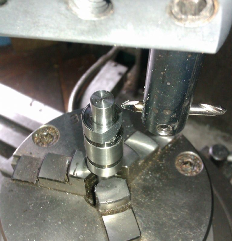
Take the scrap out and replace with your cam blank and center it up. Refit the boring head and set it running, move the table until the tool just touches the edge of the blank, raise it and put on a 0.5mm cut to the left and take a plunge cut, repeat until the tool is 5.66 off centre. Now do the same moving the table away from you until its 2mm away. Should look like this first photo. The cutting sequence is on the attached sketch, red is the blank, green is the swing of the cutter you will remove the cresent shape on the right

433988.jpg


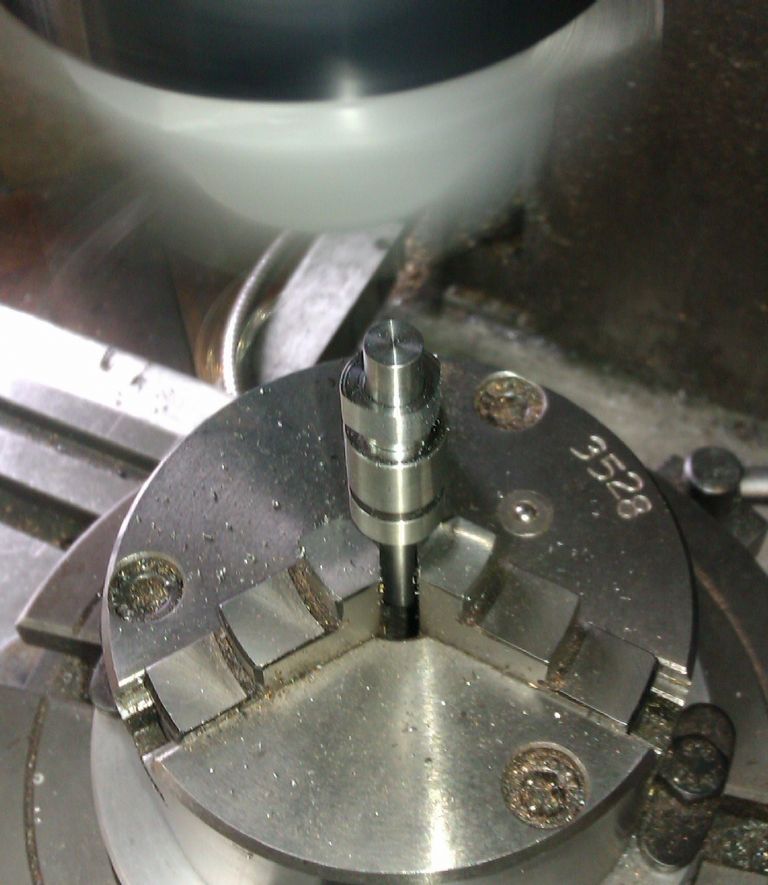
Next turn the table 1 or 2 deg depending on your chosen increments and plunge, keep repeating for the required angle. You can see the shape starting to emerge on the second attachment

Part way round

433989.jpg


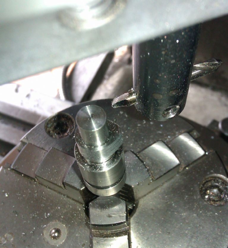
Full angle done, just needs nose radius filing on

433990.jpg


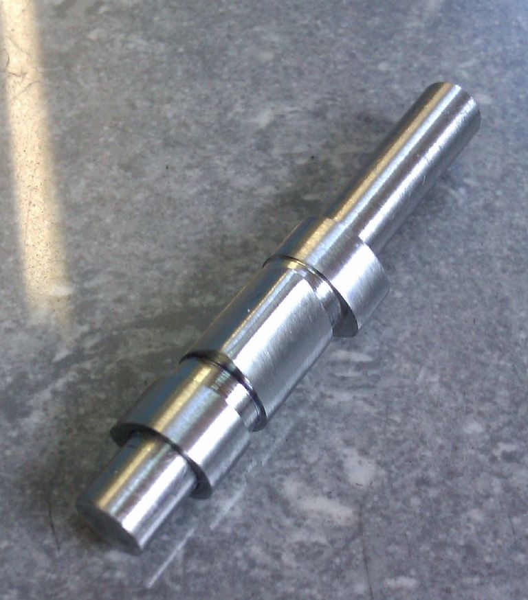
Done

433991.jpg


As you are using Randel Cox's method you do not need to set the head to one side then the other and switch to a second cutter. The whole profile is cut with the one tool in the boring head and the cam is rotated against the boring head cutter. The only other work needed is filing teh nose of teh cam.

camcut2.JPG


cam cutting.jpg
 
Cessna--I think this is what you want.---Brian
[ame]http://www.youtube.com/watch?v=IEtqETL2LXs&list=UUZB8pRNp9Plbd0-T9RmyR9g&index=18[/ame]
 
Thanks to a lot of help from people on here especially the pictures, video etc, I was finally able to produce some useable cam lobes, many thanks for your patience.
Terry
 
Thanks to a lot of help from people on here especially the pictures, video etc, I was finally able to produce some useable cam lobes, many thanks for your patience.
Terry

Glad you got it sorted but without pictures it didn't happen... th_wwp
 

Latest posts

Back
Top