You are using an out of date browser. It may not display this or other websites correctly.
You should upgrade or use an alternative browser.
You should upgrade or use an alternative browser.
Philip Duclos Gearless Hit'n Miss Engine
- Thread starter Looper7
- Start date

Help Support Home Model Engine Machinist Forum:
This site may earn a commission from merchant affiliate
links, including eBay, Amazon, and others.
Looper7
Well-Known Member
- Joined
- Dec 10, 2013
- Messages
- 51
- Reaction score
- 15
Looper7
Well-Known Member
- Joined
- Dec 10, 2013
- Messages
- 51
- Reaction score
- 15
http://youtu.be/JDe-Ppd7hHw
It is extremely exciting seeing your first internal combustion engine up and running
Jeff
It is extremely exciting seeing your first internal combustion engine up and running
Jeff
![DreamPlan Home Design and Landscaping Software Free for Windows [PC Download]](https://m.media-amazon.com/images/I/51kvZH2dVLL._SL500_.jpg)
$0.00
DreamPlan Home Design and Landscaping Software Free for Windows [PC Download]
Amazon.com Services LLC

$89.99
Outdoor Wood Boiler Water Treatment Rust Inhibitor- AmTech 300 & Test Kit
Alternative Heating & Supplies

$24.99
$27.99
HOZLY 5PCS/Lot ISO30 Tool Holder Clamp Flame Proof Rubber Claw CNC Machines Automatic Tool Changer
HOZLY

$12.56
$39.95
Complete Plans for Building Horse Barns Big and Small(3rd Edition)
ThriftBooks-Atlanta

$519.19
$699.00
FoxAlien Masuter Pro CNC Router Machine, Upgraded 3-Axis Engraving All-Metal Milling Machine for Wood Acrylic MDF Nylon Carving Cutting
FoxAlien Official

$94.99
$109.99
AHS Woodmaster 4400 Maintenance Kit for Outdoor Wood Boiler Treatment
Alternative Heating & Supplies

$40.02
$49.99
Becker CAD 12 3D - professional CAD software for 2D + 3D design and modelling - for 3 PCs - 100% compatible with AutoCAD
momox Shop

$29.95
Competition Engine Building: Advanced Engine Design and Assembly Techniques (Pro Series)
Amazon.com Services LLC

$24.99
$34.99
Bowl Sander Tool Kit w/Dual Bearing Head & Hardwood Handle | 42PC Wood Sander Set | 2" Hook & Loop Sanding Disc Sandpaper Assortment | 1/4" Mandrel Bowl Sander for Woodturning | Wood Lathe Tools
Peachtree Woodworking Supply Inc

$99.99
AHS Outdoor Wood Boiler Yearly Maintenance Kit with Water Treatment - ProTech 300 & Test Kit
Alternative Heating & Supplies

$39.99
$49.99
Sunnytech Low Temperature Stirling Engine Motor Steam Heat Education Model Toy Kit For mechanical skills (LT001)
stirlingtechonline
Looper7
Well-Known Member
- Joined
- Dec 10, 2013
- Messages
- 51
- Reaction score
- 15
First I should clarify that I have zero experience in the electrical field. having said that I was inspired by Ridders CDI switch and so I have to make one. I fried the circuit not having it grounded very well. Living in the US and not wanting to spend another $20 on a six dollar part I went in search for an alternative. I end up with the Home Depot flyswatter sapper with the coil from a different gas lighter. See link
http://bit.ly/1fwpRoR
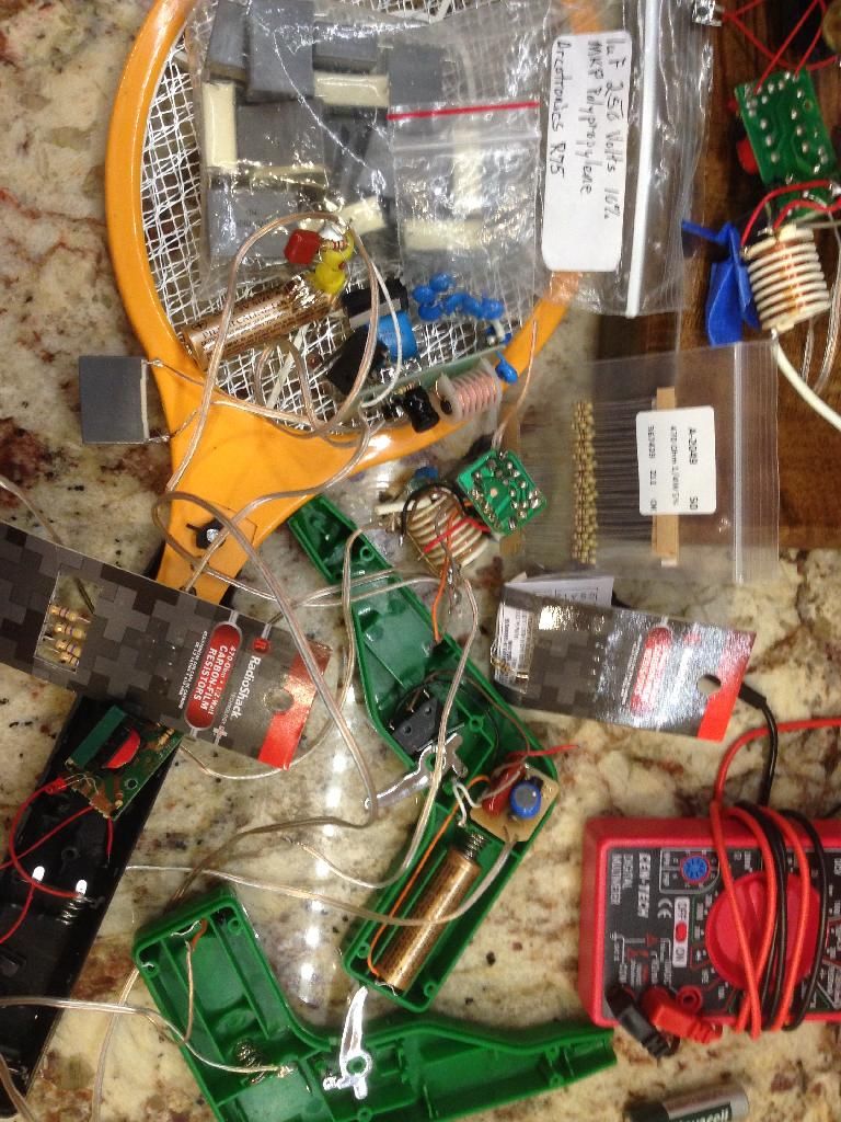
http://youtu.be/9EphioQIK0o
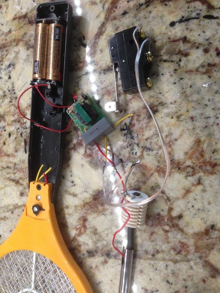
Jeff

http://bit.ly/1fwpRoR

http://youtu.be/9EphioQIK0o

Jeff

Looper7
Well-Known Member
- Joined
- Dec 10, 2013
- Messages
- 51
- Reaction score
- 15
Sorry for the slow build. Over the last four months I have doubled my income in overtime hours leaving precious few hours for self-indulgent midlife crisis hobby time.
Here is a video of my engine running with the Home Depot flyswatter circuit. The governor arm a little short so it clacks a lot but it still holds the exhaust valve open. This video is in focus and the real treat is you don't have to listen to me. Thanks for watching.
http://youtu.be/lddlInbPduU
Just the gas tank and the electrical to clean up and I can call this finished.
Jeff Hickenlooper
Looper7
Well-Known Member
- Joined
- Dec 10, 2013
- Messages
- 51
- Reaction score
- 15
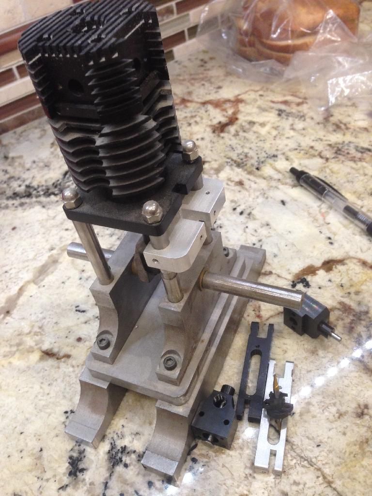
This is where my journey begins. Back in December removing from closet and cleaning 19 years of dust accumulated it was time to finish this engine I first had to find the name of the engine and where to buy the blueprints which led me to HMEM. When I started this project I had a year and a half apprentice time as a machinist. When a machine was available My boss would let me stay after work and do what I could one piece part at a time. I missed the shelf of material for G parts and the ability to anodize and black oxidize my parts with a batch of job shop stuff. After leaving the Job Shop environment I went into the composite field and it would take another 14 years before I was able to start accumulating machinery of my own.
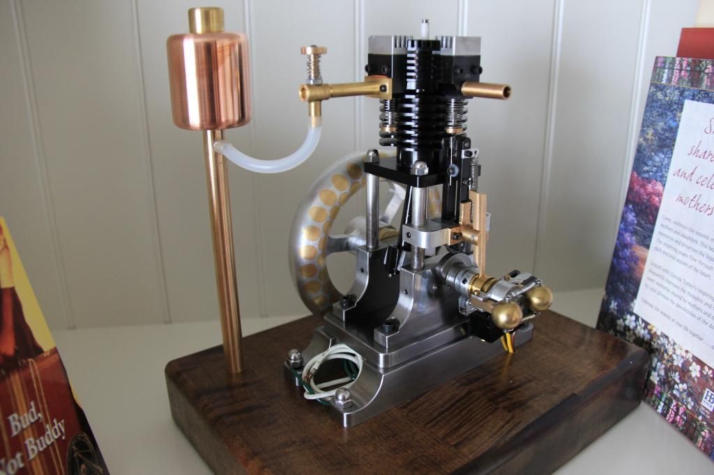
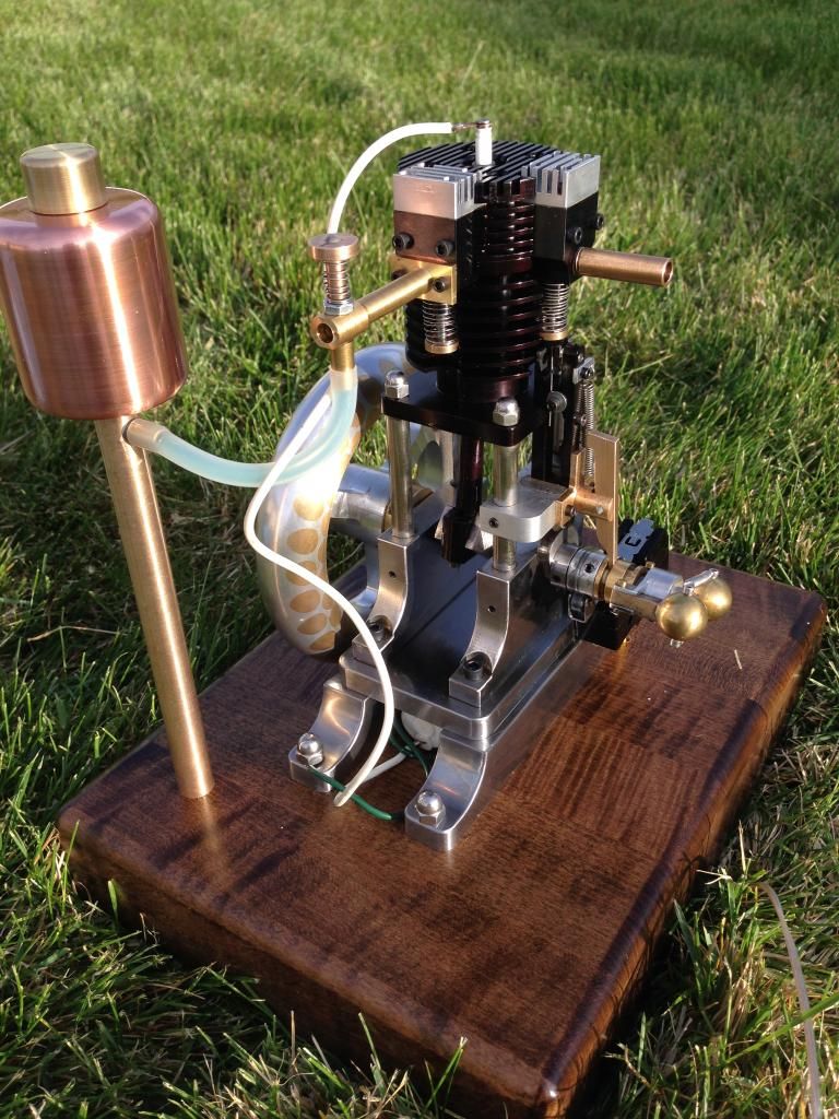
Okay here it is was a long journey for me. I have now earned a place on the wife's bookshelf. It feels so good to have it done. I've learned a lot along the way I have to say the hardest thing for me was the electrical. I can't tell you how many times I electrocuted myself. It was good for me to have a place to show my work and to have some accountability so thank you
Jeff Hickenlooper
Give Roy Sholl a call at S and S engineering. 419-452-6042 www.cncengines.com
Jeff---Take a minute and explain to me how the "gearless" aspect of this engine works please. I assume that the intake valve is atmospheric, so needs no cam to activate it. Normally, on a 4 stroke engine with a cam, the exhaust valve opens every OTHER stroke, so the cam activating it needs to run at 1/2 the speed of the crankshaft. Without gears to give this 1:2 ratio, how is the exhaust valve opening at the correct time managed?---Brian
Looper7
Well-Known Member
- Joined
- Dec 10, 2013
- Messages
- 51
- Reaction score
- 15
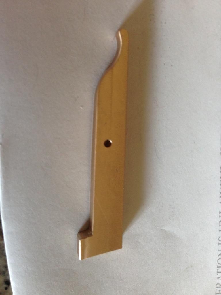
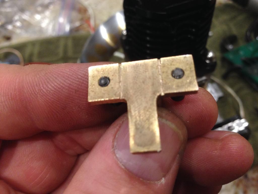
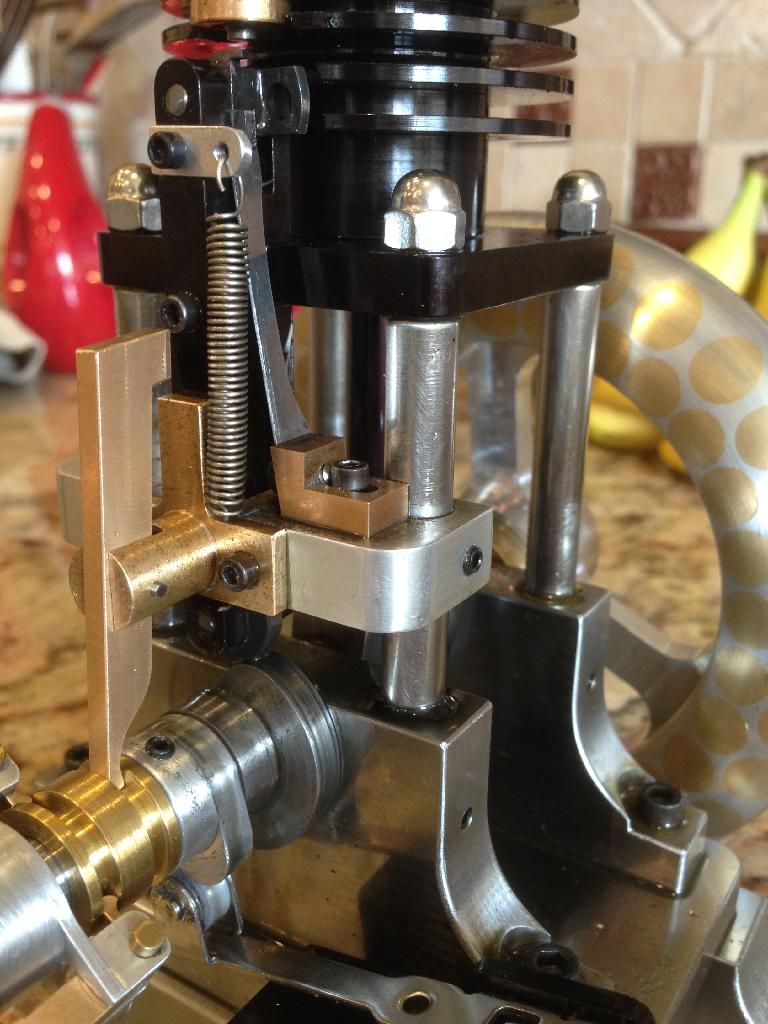
Thanks Brian. I failed to mention that it was a four stroke. The heart of the engine is the exhaust valve pushrod and indexer. briefly put the up-and-down motion of the rod rotates the indexer located on top of the rod thus activating exhaust valve.
http://youtu.be/FAJh6SCdwsM
A short 55 second video for those you like me that are more visual. Thanks for following along
Jeff Hickenlooper
http://youtu.be/FAJh6SCdwsM
A short 55 second video for those you like me that are more visual. Thanks for following along
Jeff Hickenlooper
Looper7
Well-Known Member
- Joined
- Dec 10, 2013
- Messages
- 51
- Reaction score
- 15
My diodes showed up before Roy Sholl CDI did. so I fixed the flyswatter circuit running on it now for three hours will change it out when it quits working. I do not recommend the flyswatter circuitboard but those who are brave should know that there are two different circuit boards.
ML-02/HT -- works
MLD06 -- will not work

Moving to finish projects thanks Brian and Dave for your kind words
Jeff Hickenlooper
ML-02/HT -- works
MLD06 -- will not work

Moving to finish projects thanks Brian and Dave for your kind words
Jeff Hickenlooper
Similar threads
- Replies
- 11
- Views
- 913
- Replies
- 83
- Views
- 10K




![MeshMagic 3D Free 3D Modeling Software [Download]](https://m.media-amazon.com/images/I/B1U+p8ewjGS._SL500_.png)


