Pacific Vapor Engine from Morrison & Marvin Castings

Home Model Engine Machinist Forum

Help Support Home Model Engine Machinist Forum:

This site may earn a commission from merchant affiliate links, including eBay, Amazon, and others.
Dave- those gas cocks are the cherry on the sundae ! The engine turned out stunning and I picked up a lot of helpful tips following the build. Your high standards are certainly something to try to emulate. Thanks for sharing its construction.
 
Hi Dave,

How's it going with this one? Looking forward to updates ;)

Dave
 
Hi Guys,

Sorry I have been slacking on this project; I took what I thought was going to be a short breather to work on my CNC upgrade project. Also I tore into my old Van Norman indexing head to refurbish it, along with making two missing index plates; I do need this to cut the pump gears for the Pacific. So this was necessary.

So between these projects, the extra paying work that comes into my shop, the day job, and 3 weeks ago I broke the little finger on my right hand. My arm and hand are in a cast and that has slowed me down in the shop quite a bit.

One other project I have been working on (Pacific related) are 3d CAD models for the Gould's double acting force pump that the engine will eventually run.

So don't give up hope; I will get going on it again hopefully within the next few weeks; if nothing more than to reacquaint my self with a good friend.

Thanks for checking on me,

Dave
 
Hi Dave,

That's not good news on the accident - how did you mange that one? Good luck and fingers crossed for a speedy recovery! Have you got any pictures of the pump?

Dave
 
Glad to here your still working towards the Pacific, the pump should be interesting. I have a full size 3x4 Myers Bulldozer that I used to run at engine shows. I'm quite amused at how people will spend time watching moving water.

About the finger, it's got me also wondering how you accomplished that. It's not at all difficult to get fingers or hands in harms way.
Seems I remember a picture of a rather nasty burned hand someone else posted a while ago.:rolleyes:

Be safe out there.
I'll try to remember that myself.:p
GUS
 
Hi Dave and Gus,

No this wasn't shop related.

It was Rugby the 25lb Cavalier King Charles Spaniel's fault; I had bent down to give him a pet and when I stood up and started to step over him he also stood up (which I didn't see) and tripped me. Well the rest is history; one surgery and 6 little stainless pins, a cast and I'm good to go. I get the cast off next Wednesday for a check to see how things are going. I have had it for 3 weeks now and I'm ready to be done with it.

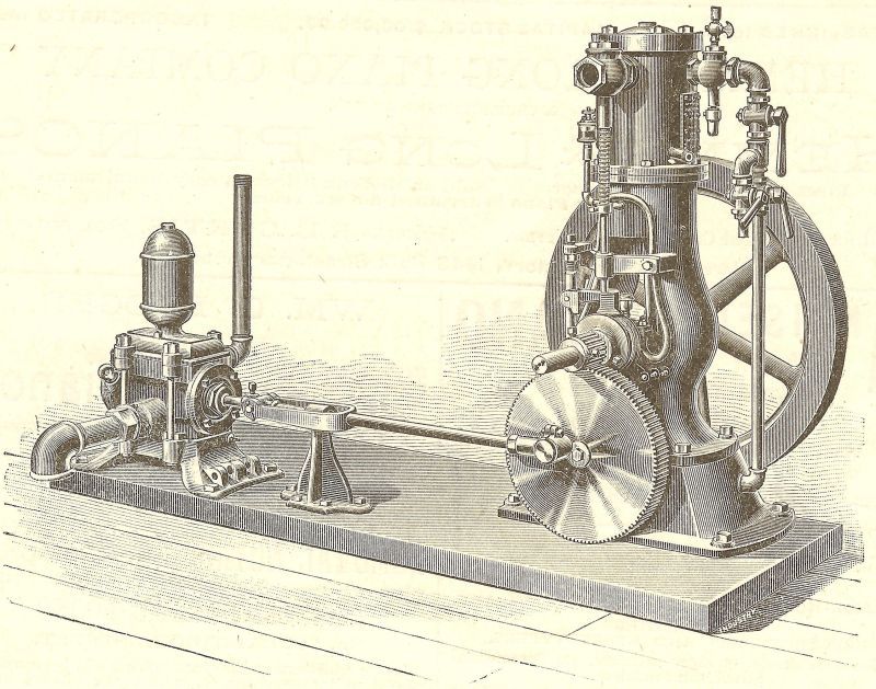
Here is a shot of the pump outfit; I'm hoping to be able to pull this off but it is going to be a bunch of work. But that's why we do this; right?

My brother who is and Auto CAD master has been helping me turn this semi iso view into front, side, and end views in Auto CAD. This in not as straight forward as it may seem because the scaling is all over the place; and there are lots of compromises to get things to look right.

I will take the 2D views and turn them into a full 3D model using either Geomagic at home or SolidWorks at the day job. all the internal features will need to be created; passage ways, check valves, etc.

I was hoping to have the whole thing completed by early fall; but the way things are going it probably isn't going to happen.

Twenty hours of overtime this paycheck alone and it probably isn't going to let up for the next few months this along with every thing else has slowed my progress to a crawl.


Pacific Vapor Engine and Pump

Thanks for checking in,
Dave
 
Last edited:
Oh, now I do like that, Dave - very nice! Unusual too, at least in my experience. You're right though, it is a long and sometimes painful process to turn what look to be detailed images into even 2D files, let alone 3D, which is something I learnt rapidly when I started pulling the Leavitt patent info together.

Dogs can be good like that, can't they? We've got a weimaraner that's had me over a few times, usually with a last minute U-turn when I'm in a rush :(
 
Spaniels... they'll do it every time. I guess they think it's funny.

That's a neat pump setup, it will be a nice addition to the project.

Pretty difficult to scale and build things from a prospective drawing, kind of a reverse 3D process with not much to base dimensions on.
 
Dave, the work on your model is an inspiration it all of us. Excellent work.

I hope that finger is getting back to normal, seems that's the big reason for the diversion. I hope to see this engine running, as I have one partly done on my bench too.

That pump looks interesting. At one time in the past I was considering making castings for that very pump, but just got busy on other stuff. You say you are making Solidworks models of it, would you like some castings too?

maury
 
Hi Maury

Thanks for checking up on me.

The finger is coming along as well as can be expected I guess; it has been a long haul. I got the pins taken out on April 4th and then the stitches 10 days later, so at this point I’m just trying to get the range of motion back to somewhat normal. It’s not keeping me from working in the shop though.

Things have gotten very busy in the home shop and I just haven’t had any time to work on my own things. The CNC upgrade project has stalled again although I did get the sheet metal punched out for the keyboard and mouse tray at work this week; now I just need to find time to get it folded up with the press brake. This is the missing piece that I need to be able to get the new control panel installed on the my mill.

I have also spent some spare time working on the pump CAD model (not as much as I would like though).

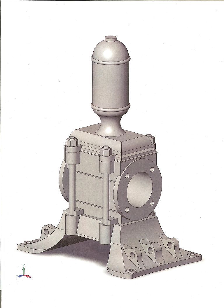
Here is a screen shot of what I have so far; there still a quite a bit of tweaking left to do on these parts, but it is a start. I have really been struggling with the base trying to get it to look right.


It’s not small, it will be over 8” tall and the base has roughly a 4”X 6” footprint. The tie studs are ¼” in diameter. I’m calling my Pacific a 1/3 scale model of a 3/4hp engine. That makes the pump about ½ the size of the engine. I think it will make a nice display.

Castings? I hadn’t thought that; my plan was to machine/fabricate the whole project; leveraging heavily on the CNC. I’m not sure what would be involved it turning this into castings.

Dave
 
Dave, I will be leaving for NAMES on Tuesday, be gone for a week, but can give you some specifics about making patterns when I get back. When you have a model you are happy with send me a copy. What version of Solidworks do you have, I have 2013. I understand there are incompatibilities with opening files of different versions.

For making patterns:
First thing is to decide what sections will be separate parts. make a model of each.

What I do then is to add material to the model for all of the machined surfaces. Also, material for a core print is added at this point if there is to be a core in the part.

Second, I scale the model for shrinkage.


Third, If the part needs to have a cope and a drag, 2 piece mold, I do a split along the parting line and convert the part into 2 parts.

Last I add draft, about 1.5 to 2 deg on external surfaces and 2 to 4 deg on internal surfaces.

Then I CNC the part out of a soft material like REN Shape or cherry wood.
This can be used as a pattern.

If you heed a core box, such as the bulb on the top of the pump, a core box can be made by making a model of the cavity and cutting it out of a solid block.

This is just an overview, can add more detail if you want to go this rout. If you want I'd be willing to help, and I can cast some parts out of bronze.

maury
 
Dave, looking at the model you have drawn, I have a few suggestions for dividing up the pump if you want to go with castings.

The bulb on top with the finial on the bottom would make a nice part. There needs to be a hole on top for a core print, so there would be a threaded finial on top too.

the base holding the bulb would make a nice part. I assume there probably is some valving and porting inside this part.

The main section with the cylinder is an obvious choice. The cylinder would want to be cored out too. If not, shrinkage would become a problem.

There need to be end caps, I assume you have not drawn these yet.

The base I would make in 3 pieces as the parting line on the casting could become messy. The other option is use a core and cast the part up side down. I'd want to see the details of the model on this part.

Some ideas.

maury
 
Hi Maury

I hope you had a good time at NAMES and also a good trip.

Wow what an incredible offer on the castings; this would be a wonderful learning opportunity for me as I do have interest in the pattern making area. Casting maybe someday but that would be down the road a ways (retirement) as I just don’t have enough time for my current projects.

The pump as it stands now is 3 parts, the base, the middle section, and the top cover which includes the pressure dome. There will also be the end caps and packing gland but these will be made from bar stock.

I haven’t put any of the internal passages in at this time; I wanted to get the outside shape so that I was pleased with it. Then start to figure out how to do all the internals. Making cores will probably put a whole different twist on what can be done.

I would love to make all the patterns and core boxes.

Thanks again, if this works out it will be fun project


Dave
 
Dave,
Do you have any clue what the six vertical flanges with horizontal holes on the base are for?
Alan
 
Hi Alan,

Yes; the flanges were to attach handles for manual operation. on some of the pumps there was a handle on each end so two guys could work the pump at the same time. The pump would have been available as a hand operated unit or powered with the optional drive assembly. This is based on my observations looking at the old Goulds catalogs.

Attached is a similar pump from about the same time period; this pump is probably about 5 years newer based on the copyright of 1895 in the catalog.

Maury and I have been busy on the pump project and I have been able to spend some time working on my engine yesterday and today.

I should have some sort of an update in the very near future.

Thanks,
Dave

Untitled.jpg
 
The base I would make in 3 pieces as the parting line on the casting could become messy. The other option is use a core and cast the part up side down. I'd want to see the details of the model on this part.
maury

The base looks to me like a case for using an oddside.

Apart from allowing a non-planar parting line, it often helps to ensure better registration than is achieved with a split pattern relying on worn moulding boxes for registration.
 
Hi everyone,

Work has started to progress on the pump and related drive components and I finally have some progress pictures to share. Maury from Lone Star Engine Works has graciously offered to help me create castings for the Goulds pump and drive assembly; we have both been busy working on this part of the project most of the summer as time allows. Maury is very skilled at machining, pattern work and metal casting and this has been a wonderful opportunity for me to learn more about this part of our hobby.

I have the 3d models mostly complete and Maury has been taking my models and doing the necessary operations to turn them into patterns, adding machining allowance, draft, core prints, and scaling for shrinkage. We both have been making patterns and core boxes and I will have an update showing some of this work moving forward.

If you look back at post #207 you can see a drawing of the pumping outfit. I purchased this original 1892 advertisement off eBay many years ago; having no idea that someday I would be building the engine, I just liked it. After starting on the engine it was always my desire to make the pump too. The missing part of the equation was, how is the large bull gear mounted to the engine. A photo loaned to me by Lester Bowman (the original creator of the Pacific Model) answered this question.

Now, knowing how the gear is mounted and that it was a bolt on attachment to the engine I thought I just might be able to pull this off.
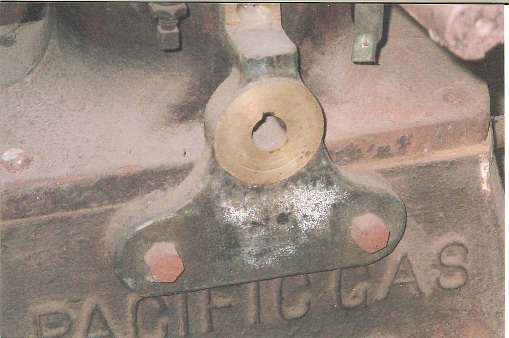

This is a photo of an original bull gear bracket mounted on the engine base and crankcase. There is a real good chance that this is the only one of these in existence. Photo complements of Lester Bowman.
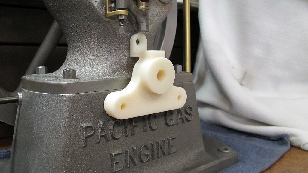

I started out modeling the bracket and working out gear sizes that would best match the original and still fit the model. Once the design seemed like it was going to work, the parts were printed to check the fit on the engine.
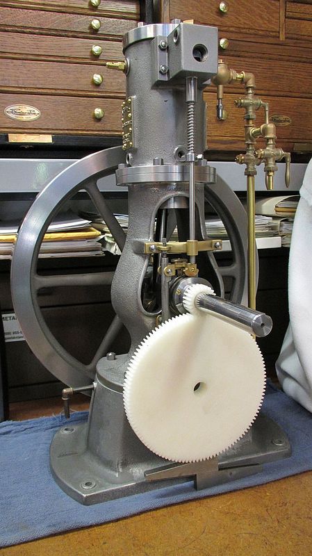


Here is the SLA gear set being checked to see how the gears are going to look mounted on the engine.
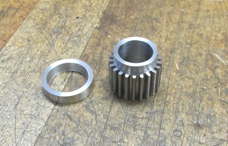

I was going to make the gears but this is a another area where Maury offered his assistance. Maury made the pinion gear and I finished it by adding the collar. If you look back at the original you can see the gear has this collar where the set screws are to mount the gear to the crank shaft.
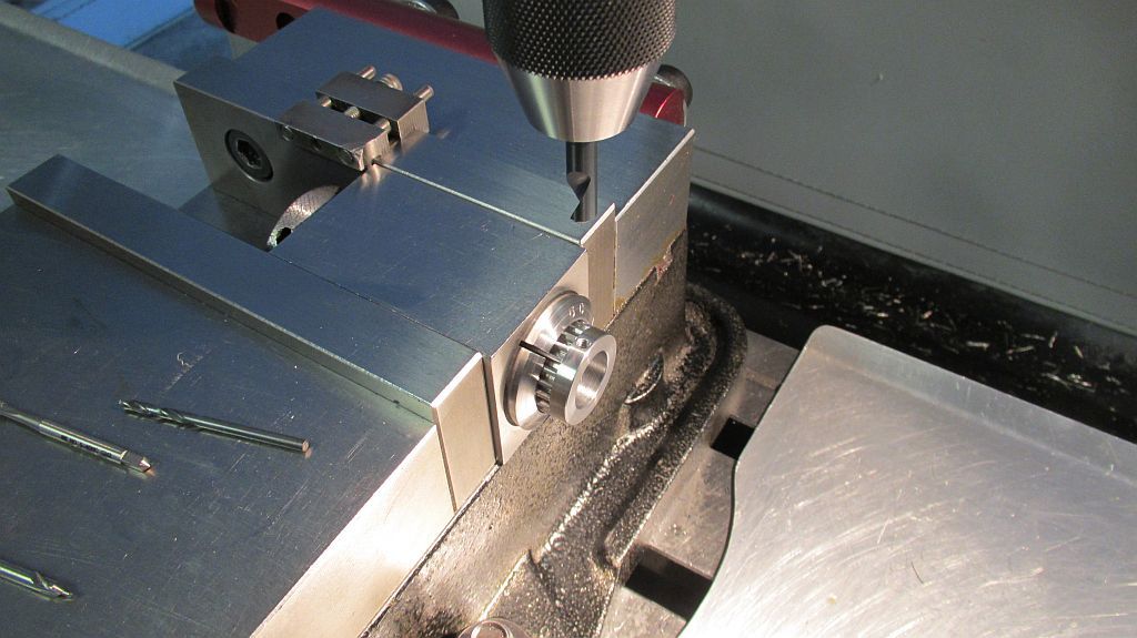

After the collar was turned and pressed onto the gear it was set up in the mill using a collet block to add the setscrew holes.
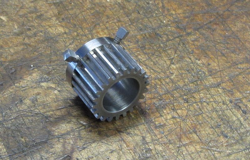

A pair of period correct square head setscrews were made and case hardened.
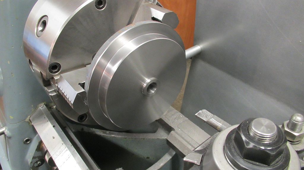

I machined my bull gear blank from a 6” slice of gray cast iron, and then sent it down to Maury where he used his gear hobber to cut the teeth. The gear came out beautiful, Maury does nice work!
Here the blank is faced, turned, and bored.
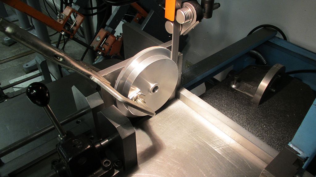

The band saw was used to slab off the extra material for use on a future project.
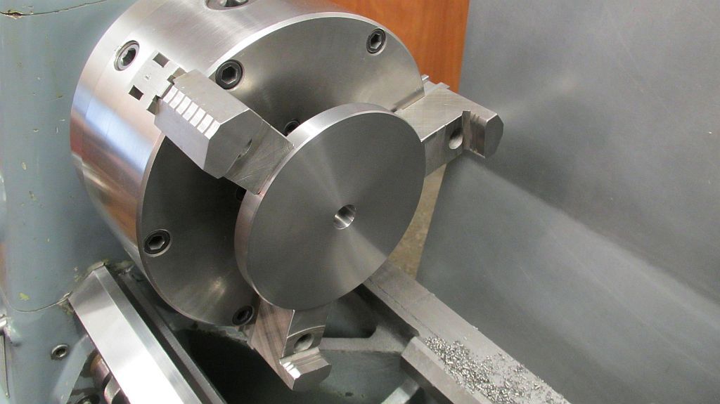

Back in the lathe the other side of the gear blank is faced to proper thickness.
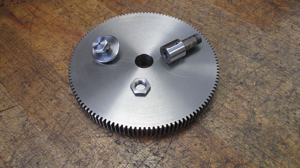

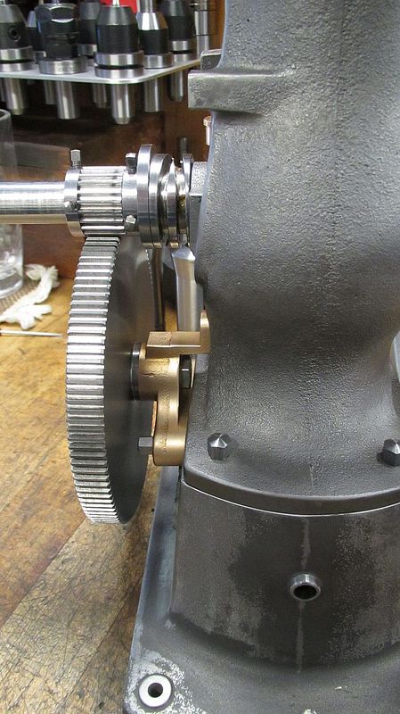
Here is finished gear with the related hardware. The shaft was case hardened and polished and the iron gear will run directly on the shaft. If it gives me any trouble down the road I will install a bronze bushing. An oil hole was drilled through the bolt and the shaft also drilled to allow for oiling of the gear. Check out those nice teeth!
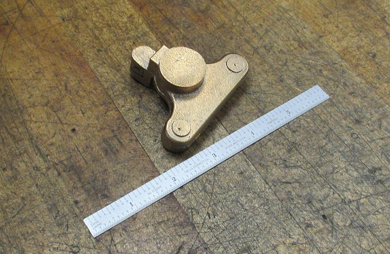

This is the first casting produced, Maury machined the pattern for the bracket and poured the casting. If you looked closely at Maury’s F&G thread you can see this casting was included along with the pump parts that he had cast for the F&G engine.
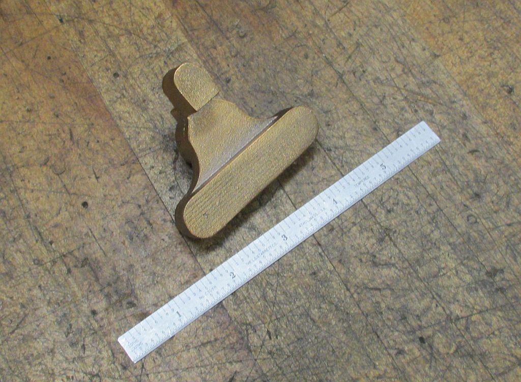

Back view of the same bracket.
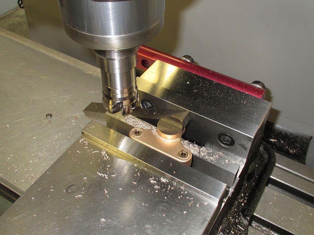

After a little fettling the casting is set up in the vise; a light skim is taken across the pads and the mounting holes drilled. A light cleanup cut was also taken across the gear surface, it will be further machined later on.
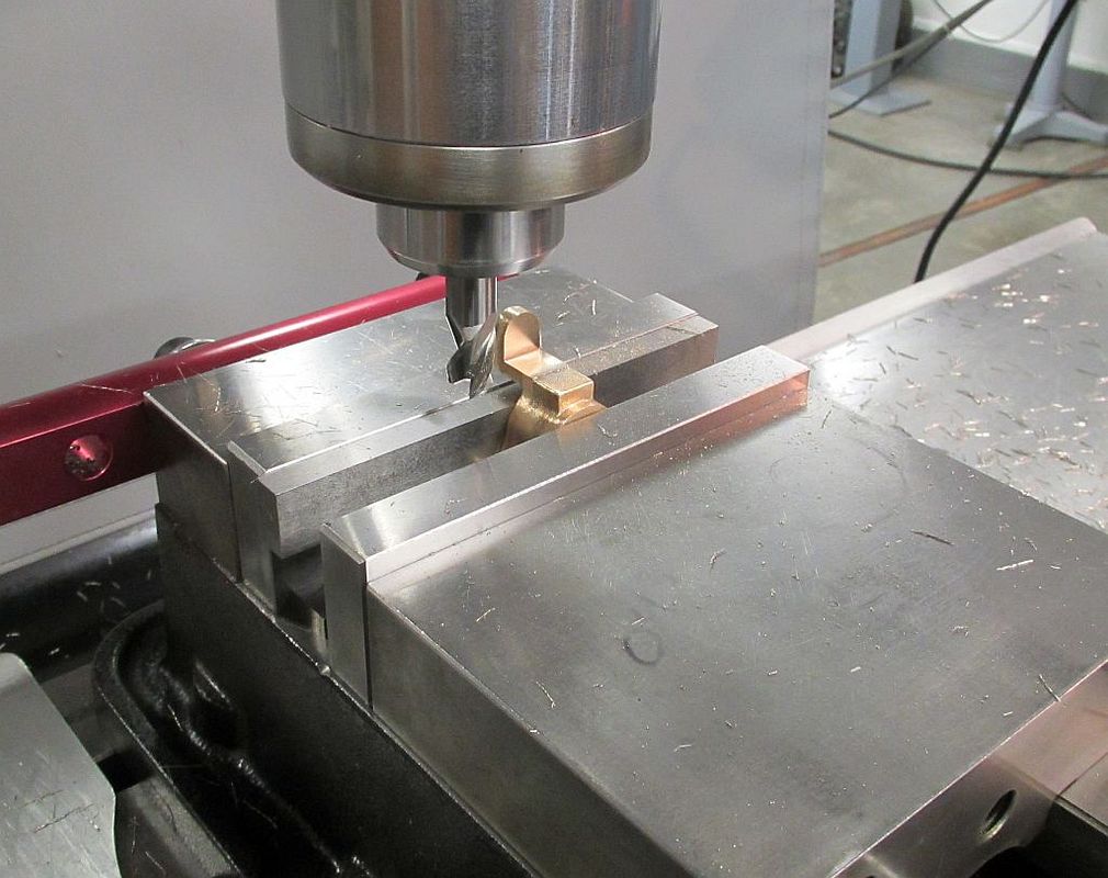

The upper mounting lug is machined to proper thickness.
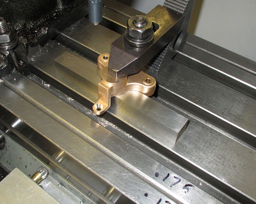

The upper mounting lug is drilled and counter sunk using the same datum surface as the first operation.
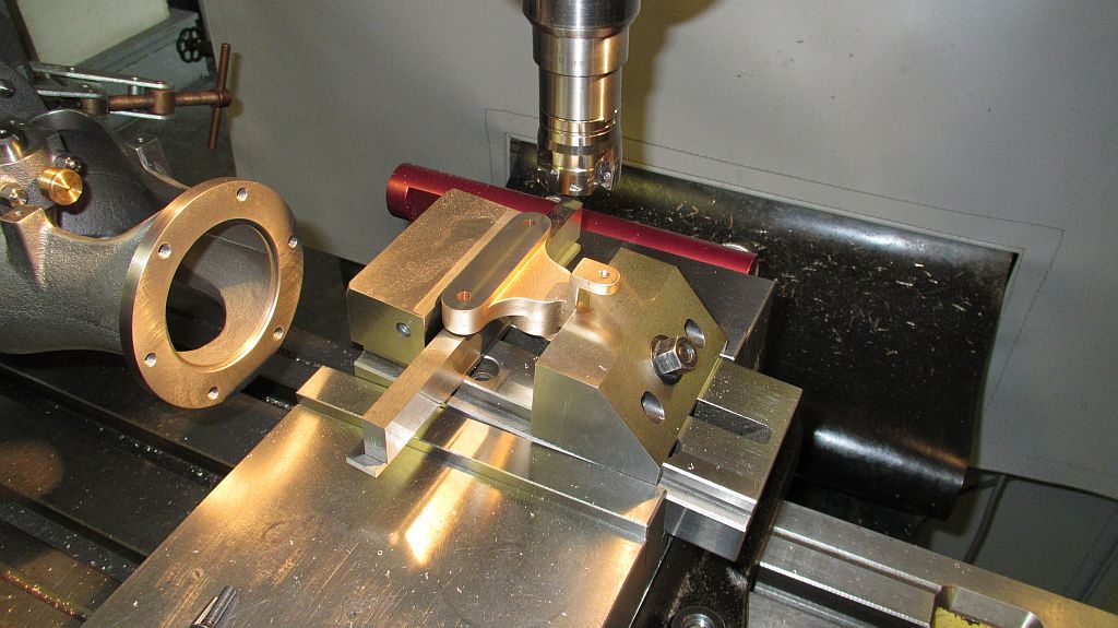

A light skim is taken to true up the 5deg. of the mounting surface.
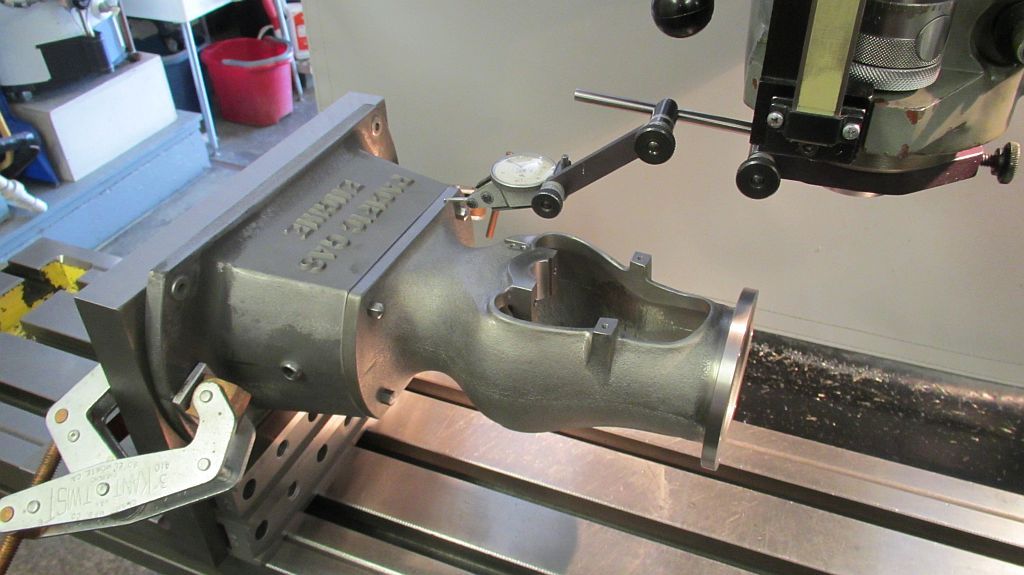

The engine was disassembled and mounted on an angle plate then dialed in. The crank shaft center line was also established at this time.
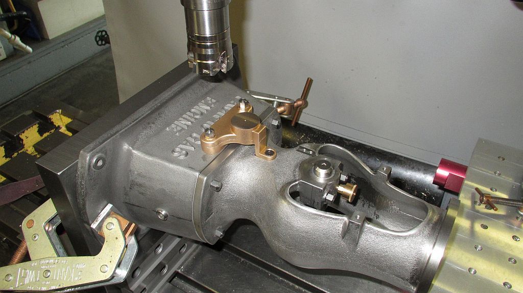

Working from the crank center line the mounting holes were drilled and taped in the engine castings. A pair of high crown dome head bolts were also machined to mount the bracket to the engine. The modern flat head screw will be replaced with a proper slotted head screw later on.
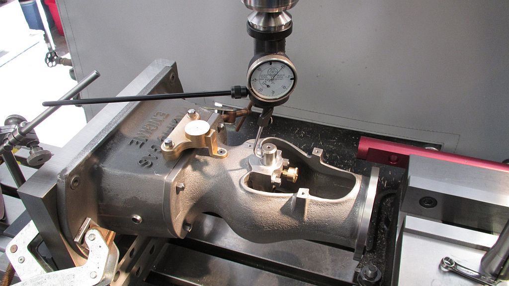

Using the Blake Coax indicator to pick up the center of the crank axis.
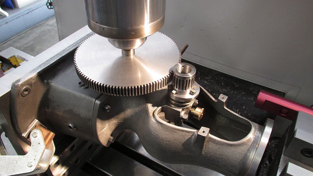

Checking the gear mesh before boring the shaft hole.


The shaft hole was drilled and bored; also at this time the bracket was faced using the facing head to insure the face was perpendicular to the shaft axis.
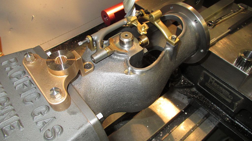

I took the opportunity at this time to drill, tap, and spot face for the spark saver still needing to be made.
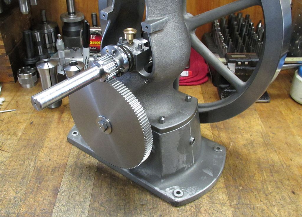

Here the gears are mounted on the engine (they run real nice!).
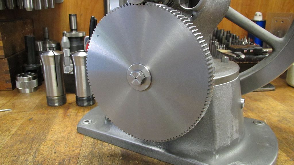


I can’t express how happy I am to see the gears mounted on the engine. This has been a dream of mine since I started the construction of the engine; this is a milestone for me and now I can see that it is going be a reality. The rest of the pump is coming along nicely and there will be updates coming showing the construction of the pump. Hopefully Maury will also be able to share some of his work along with mine.
I would like to thank Maury for offering to dive into this project with me and share his expertise; we both have been having a great time collaborating and sharing ideas; and I’m getting an education on the casting process. If not for him I wouldn’t be nearly this far along.

Thanks for checking in,
Dave
 
Hi everyone

I managed to carve out a little bit of time over the holidays to work on the Pacific. I didn’t get very much done but every little bit get me closer to the end.

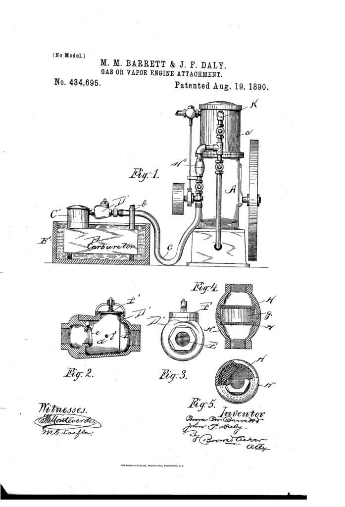
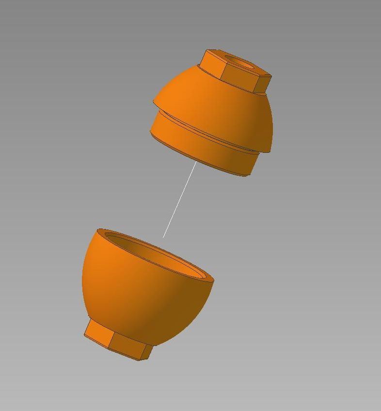
There are a couple parts (safety devices) that go in the fuel inlet piping between the vapor carburetor and the engine. The first one is the flame arrester; this device has a stack of metal screens inside a housing that in the event of a backfire will quench and extinguish a flame that is moving back up the pipe.

The next piece is a check valve/ relief valve assembly that mounts directly on the vapor carburetor. In the event of a backfire the relief valve opens and vents the excess pressure which keeps it from trying to push back into the carburetor. Also contained in this assembly is a swing check valve that opens when the engine pulls vacuum to let fuel through and then seals when the vacuum is removed.

I started with the flame arrester and then will move onto the check valve assembly.
Below is the patent that I have been working from; you can see both of these parts in the drawing and how they are used.


The flame arrester was modeled in Geomagic; Using the existing piping and hand cocks as a guide I played with the size and shape until I came up with something I was pleased with.


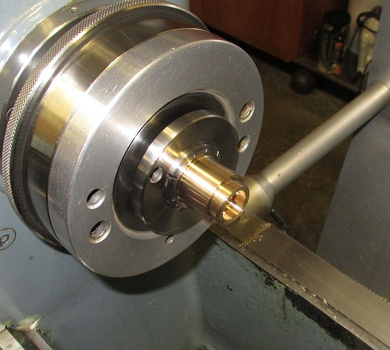
Starting out the insides of both the top and bottom were machined; leaving the bottom half long for something to chuck on to.


The top was screwed onto the bottom and then faced to length.


Here the top section has been machined to length.


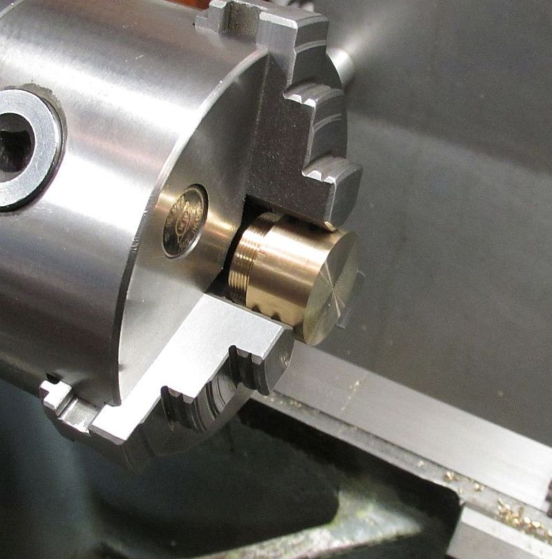
The stock won’t fit in a collet so the bottom was held in a 3 jaw chuck and also faced to length.


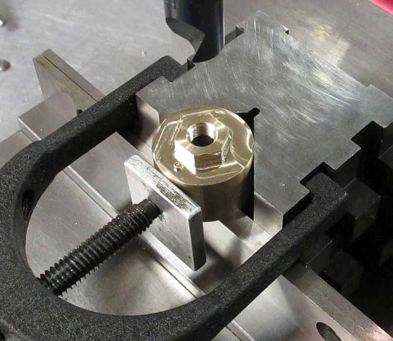
Both the top and bottom had the hex cut and the 1/16” NPT threads put in.


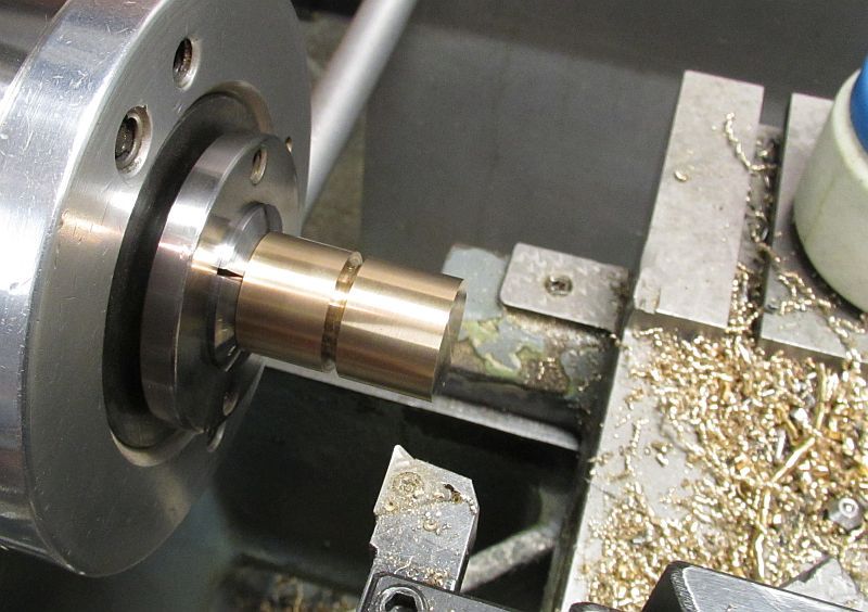
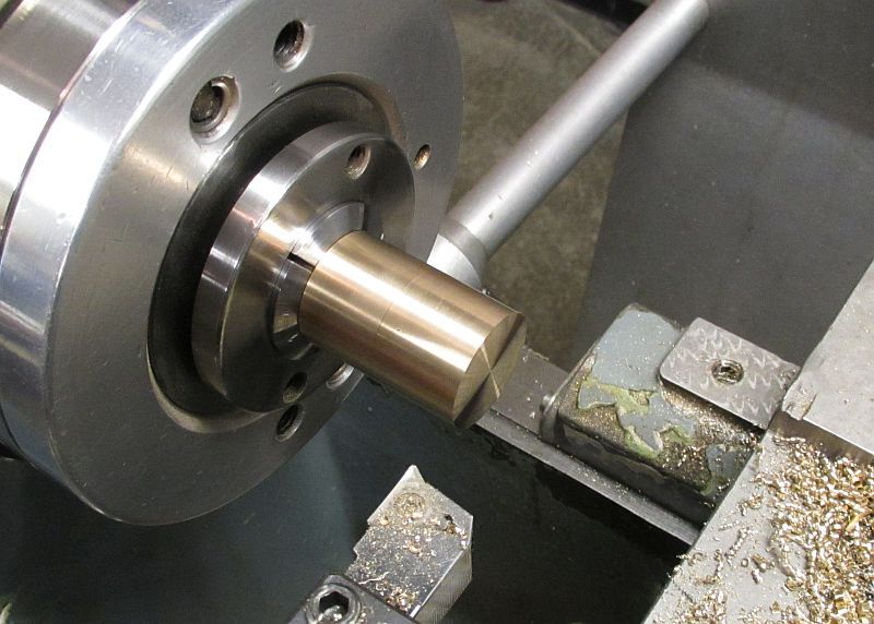
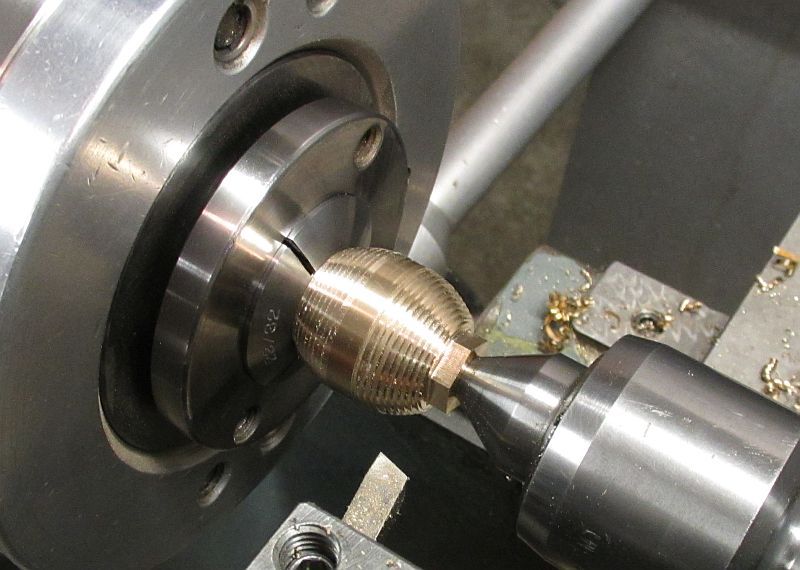
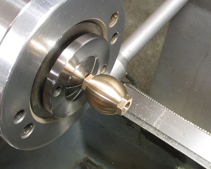
I used the step and cut method to generate the profile of the oval shape. One end was held using a ½” hex collet then when flipped around to profile the other end a round collet was used on one of the steps. This worked out better to maintain concentricity end to end.


After some hand work with files and sand paper here is the final shape.


I still need to punch out the stack of screens to fit inside but the will be done later.


Here it is installed on the engine; I’m pleased with how it looks and complements the other parts on the engine.


I have also made a good start on the check valve assembly and will hopefully have an update on it in the near future.
Thanks for checking in.
Dave
 
Back
Top