- Joined
- Jan 17, 2009
- Messages
- 887
- Reaction score
- 82
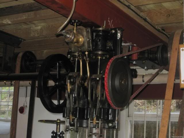
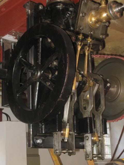
Some time ago I spotted an interesting engine at Quarry Bank Mill Style, I didn't recognise the type but after asking around I found out it was an Reverse Crank or Over Crank engine, this particular was quite small no bigger than a suite case, mounted vertically from a beam and was being used to power a small workshop. Here's a few pics of the particular engine.


The cold weather we've bin having in the UK has driven me out of the shop, so I've bin keeping myself warm in doors on domestic duties and to keep me sane I've started drawing up the engine 1/3 scale as a project to start as soon as things warm up.
I've attached the drawing as PDF files to give you an idea of the design, my plan is to make the engine from bar stock with the exception of the fly wheel which will be cast iron you can get these quite easily from trade, for the cylinder I'm going to fabricate this up from brass.
If things work out OK I'm planning to fit a governor to the engine, and mount it vertically on a board (painted to look like brick) with some line shafting on the back that the engine will drive, but we'll see how things work out first.
I've only skeemed out the governor drawing I'm planning to adjust the spring tension so that i can vary the speed of the engine through the governor, which brings me to a ?. How do you adjust the speed a governor controls an engine a can think of:-
Adjust the weight of the balls
Adjust the spring tension.
Vary the drive pully ratios driving the governor.
Can you can add to this ?
Any comment you guys have will be much appreciated.
Stew
View attachment Side View Assy-Model.pdf
View attachment Plan View Assembly-Model.pdf
View attachment Connecting Rods-Model.pdf
View attachment Crank Shaft Bearing Housing-Model.pdf


![MeshMagic 3D Free 3D Modeling Software [Download]](https://m.media-amazon.com/images/I/B1U+p8ewjGS._SL500_.png)


