Old School Sawmill Edger

Home Model Engine Machinist Forum

Help Support Home Model Engine Machinist Forum:

This site may earn a commission from merchant affiliate links, including eBay, Amazon, and others.
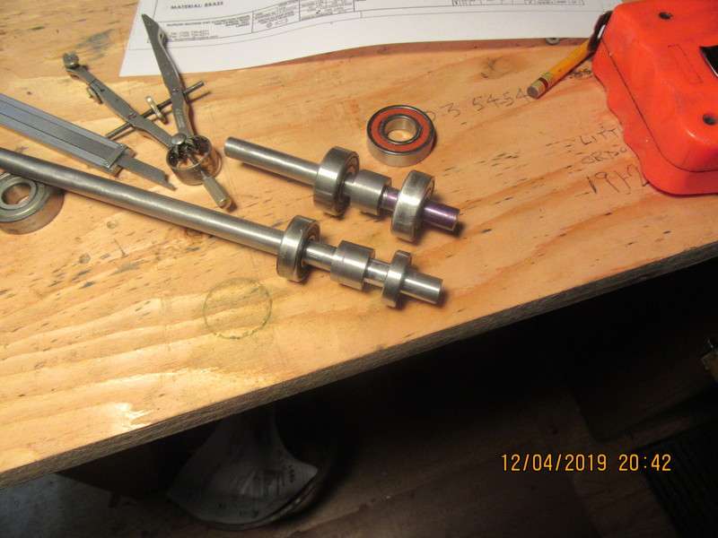
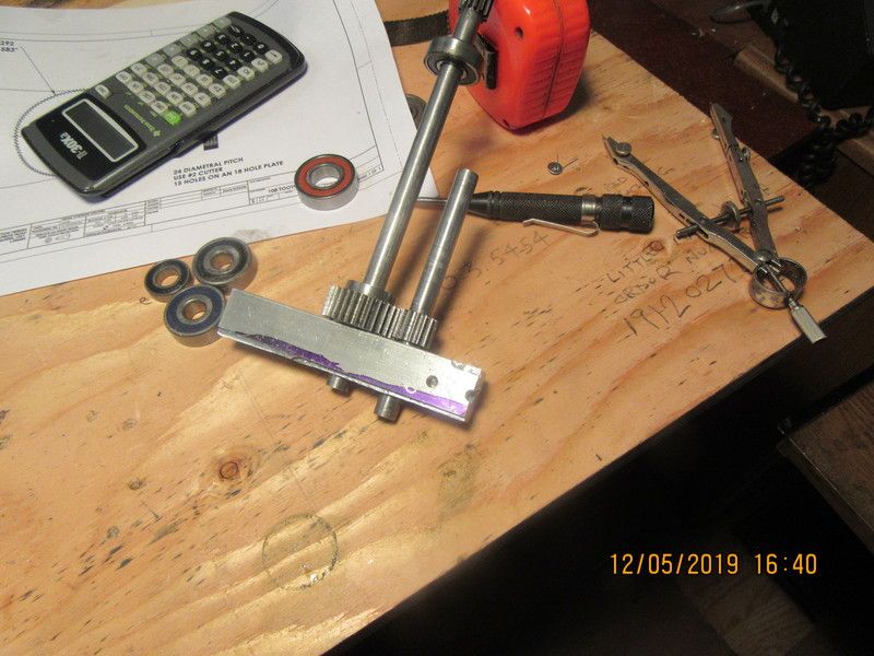
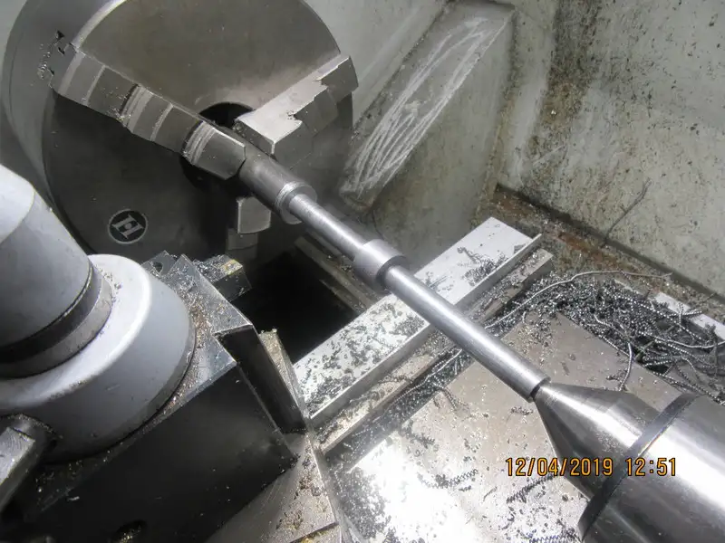
There are a couple of 14 tooth gears in the new gear reducer I an building, and it is actually simpler if I make the gear and the shaft that supports it all from one piece. This picture shows the first blank, ready to have teeth cut in it. I used the auto feed running in reverse on the turned down area closest to the chuck. It worked fine, but felt very weird watching the cutting tool and carriage moving from left to right.
PZD3sN.jpg
 
So---It's been a long and uneventful day, but I have two shafts turned to size and ready to have gear teeth cut into them tomorrow. Turning shafts to fit bearings is not one of the machine shop jobs that I really like. I have ruined so many pieces of shafting by trying to get that last thou off the diameter and then ending up undersize. Steel is funny stuff. Unless the lathe tool is razor sharp, it won't cut that last thou--it just burnishes the shaft. Then when you turn it in one more thou, it digs in and takes off more than you wanted it to. I generally take shafts down to about 0.002" oversize, and then work the final bit off with carborundum paper strips until it is a "perfect" fit. Sounds good if you say it real fast, but my thumbs are sore tonight from holding sanding strips.
tVYPap.jpg
 
Brian, what grit do you start with for the carborundum strips? I generally aim for .001" max over-size when I am going to do this, but have occasionally missed high and had to take down a .002 overage. I use two different grits, 180 and 320; if I am close (< .001"), I start with the fine grit, but if I am not that close, I can get it close pretty quickly with the coarse grit.
 
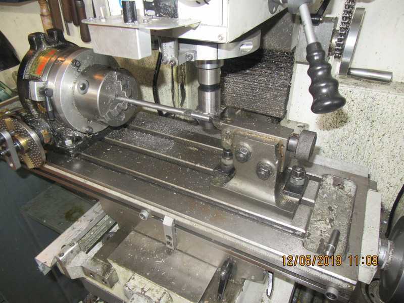
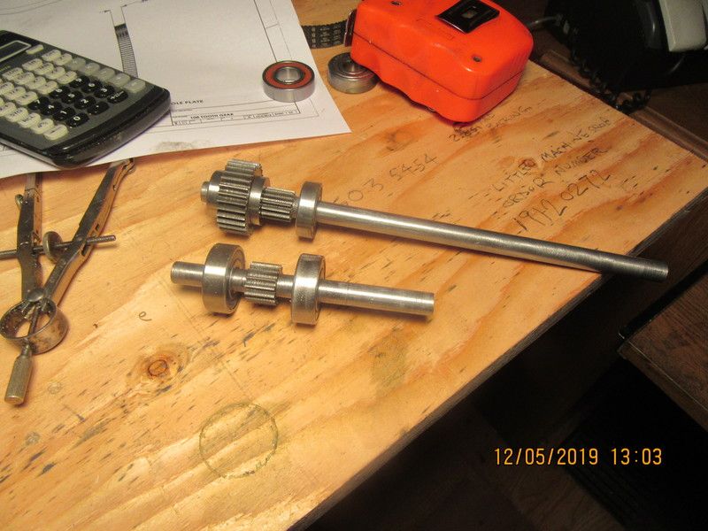
I've had a very gearish morning. We have one set-up shot and a shot of the three finished gears. No real excitement, I have the entire procedure written down in my "Gears" notebook. I don't do this very often, so it's nice to have something written that I can look over before I start machining. There is one more gear, made from brass, but it's a big one, over 4 1/2" diameter. I called my metal supplier to ask how much it would be, and he said "If you have to ask, you can't afford it!!"I have a good size piece of 1/4" brass plate that some kind soul gave me a few years ago, so I am going to laminate two pieces together and cut my gear from that. Now I have to go shovel the front step and go for my fat mans walk.
MBiRCg.jpg

PJ69eo.jpg
 
Beautiful gears! I assume the larger one is keyed onto the shaft with the integral smaller gear?

With regard to the large brass gear - are you using brass for wear purposes? Wonder what a piece of phenolic or delrin or such would cost - I would think either would be cheaper than brass, but I haven't actually tried to source either in the size / shape needed for a gear blank.

I too have a large-ish plate of brass, close to 1/2" thick in my case, with some odds and ends of holes in it from its previous life. Every time I come to something that could use a large piece of brass, I find myself hesitating - is *this* the project I want to use this on? What if I use it now, and then *really* need it later on? Based on the history thus far, I'm guessing this piece of brass might be buried with me!

With regard to the sanding strips - I woulda thunk that 120 grit would get you there within a reasonable length of time. Are you using cutting oil with the strips? Especially, are you regularly floating off the build-up of swarf?

What I use are billed as "emery cloth" - don't know if that is any different from the carborundum strips you are using ...
 
I haven't actually got that far with my plan, but I'm thinking a .093" cross hole drilled thru the very large gear that I haven't made yet and shaft for a Loctited in place 3/32" cross pin. The larger gear that I have shown in the picture has enough hub sticking out one side to put a couple of set screws in, but I hadn't planned on keying it. I don't use cutting oil with the strips. All that does is immediately gum everything up and then the strips won't cut. I just went into my shop and read the printing on the back of the strips. Surprise!!! It's not carborundum, it's aluminum oxide.
 
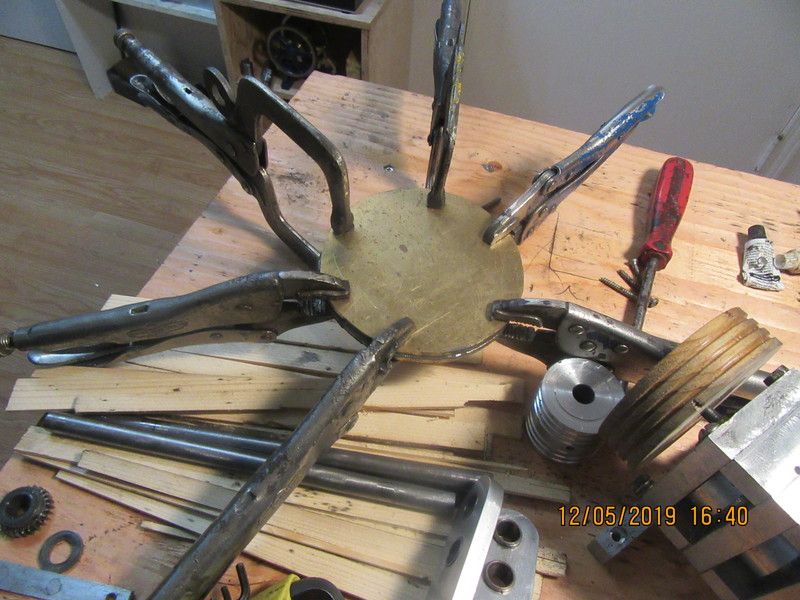
Whenever I cut a pair of gears, I always drill and ream two holes the exact calculated distance apart in a piece of scrap material and insert the gears and shafts, then turn them by hand to test how they mesh. Most times it works alright, but I have been fooled in the past. I can generally live with a bit of extra "lash" in the mating gears, but when they are a bit oversize, it gets ugly pretty fast. If they are a bit oversize, you can either set them back up in the lathe and recut them, which is a pain in the $#@%, or you can change the design of the housing a bit to accommodate them. Also, you can see my two pieces of 1/4" brass plate, rough cut to 4 3/4" and joined with J.B.Weld, then clamped. I will also bolt them together after they set up for 24 hours.
WWwgbg.jpg

Bmk37A.jpg
 
I don't use cutting oil with the strips. All that does is immediately gum everything up and then the strips won't cut. I just went into my shop and read the printing on the back of the strips. Surprise!!! It's not carborundum, it's aluminum oxide.

Interesting that we have different experiences - for me, though I can use the emery cloth dry, it doesn't cut nearly as long, as it loads up with swarf, and there's no easy way to clear it. By contrast, cutting oil helps to "float" the swarf out of the grit; sometimes I just squirt oil on the emery strip, floating the swarf, but if that doesn't seem enough, I work the oil around a bit with my fingers, and then wipe it off with a paper towel, restoring it nearly to its original appearance before use. Could it be a different type of grit? I'll try to look to see what the "emery cloth" uses for grit when I get a chance to go out to the garage.
 
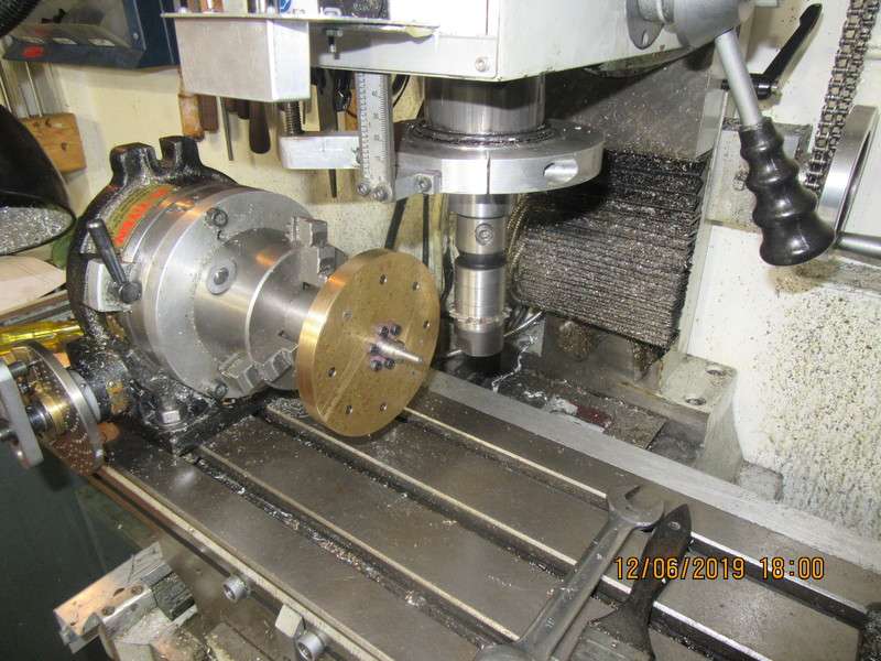
So here we are, ready to cut the 108 tooth gear. The two pieces of 1/4" brass plate were "glued" together with J.B. Weld, clamped and left overnight under a heat lamp. The outer circle of bolts hold the two plates together permanently--I don't trust any adhesive in an application like this. The inner circle of bolts pass through the plates and are threaded into a 1.5" diameter steel stub-shaft that is held in the jaws of the chuck on my rotary table. Before the stub-shaft was bolted in place, the brass plates were set up in my lathe 4 jaw chuck to drill and ream the 1/2" center hole. The stub shaft was also drilled and reamed for a 1/2" shaft, and you can see the end of it sticking out past the face of the brass plates. The big deal here is to achieve absolute concentricity before I start to cut the gear teeth. A dowel with a pointed end was first secured in the chuck, and then the center of the cutter was adjusted to be perfectly horizontally in line with the point on the dowel. Then the table was fed towards the column in the Y axis until the major diameter of the brass just touched the major diameter of the cutter. Then with the table cranked back out of the way in the X axis, the table was advanced 0.089" in the Y axis. This is the depth of cuts to be made. The table stops were set so that the cutter just cleared the brass part in each direction on the x axis. I am now ready to start taking full depth cuts every 3.333 degrees. This rotational distance is set by using the divider plates on the front of my rotary table.
bwo314.jpg
 
So, here we are with the completed gear-train for my new gear reducer. I cut the 108 tooth gear this morning, and after finishing it I set all of the gears up in the correct relationship to each other, and took it for a test drive on my milling machine.
 
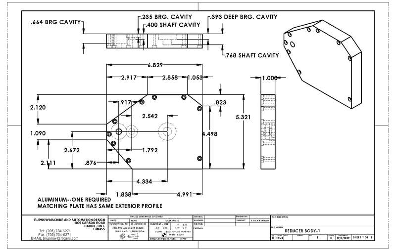
The two main outer plates of the reducer have the exact same outer profile. Of course they have different cavities machined in the in facing side because of the mish mash of bearings I used. The easiest way for me to do this is to extend the small diameters of the blind bores completely through the plates. That way I can pick up on the bores when I flip the plates over to mill the cavities. There will be no pressure in the reducer, just lots of gear grease, so if I do extend the bores all the way thru each plate, I can glue in plugs after the fact. This makes my job a lot easier, and takes nothing away from the functionality.
gDQc1U.jpg
 
Last edited:
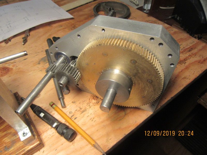
Today seen the gears assembled with the first side of this reducer housing. The overall ratio will be 16.5:1. There is one trick thing going on here that I like. The 16 tooth pinion shaft sets so close to the mating 30 tooth gear that there is not enough room for two ball bearings to set side by side. That is why the reducer sideplates are 1" thick. This allows me to put in a deep counterbore for one of the bearings and a shallow counterbore for the other. That way I can run the ball-bearings with one setting in deep enough to clear the other.
YCGM0d.jpg
 
This is a video of the reducer running. The gears are all finished and the shafts are all supported on sealed ball bearings. I still have to make and install the perimeter plates that enclose everything, as this reducer will be full of grease.
 
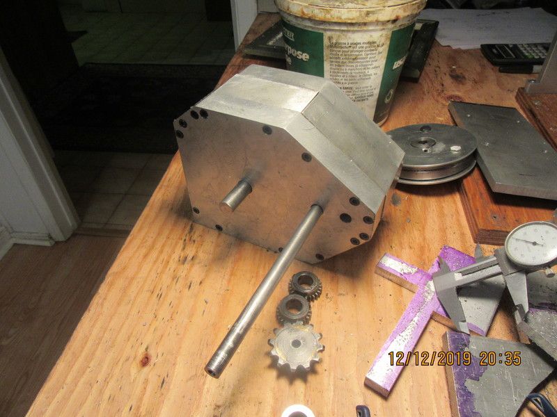
Today I made up the seven individual plates which form the perimeter of the gear reducer housing. Each plate has 4 drilled and tapped holes in it. Somewhere about half way thru, it must have driven me mad, because I thought "Now would be an opportune time to grease the gears before I get everything buttoned up!!" Of course by the end of the day, all of the grease is polluted by aluminum dust, so will have to be washed out and regreased. You have to admit though, it is a very swoopy looking gear reducer. It will look even swoopier after I wash out the bad grease, refill with good grease, and introduce reducer housing to Mrs. belt sander.
L7DfbS.jpg
 
Very cool assembly (again) Brian. You’ve inspired me to give it a try and make my own gear reducer for a sand muller I’ve been thinking of building. If nothing else I guess I have 3 months of winter to play with the idea.
 
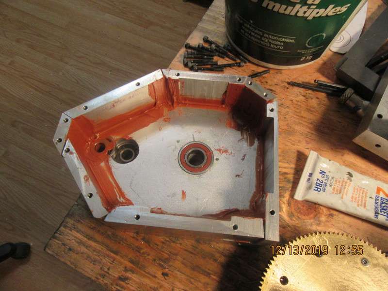
So, today you get a look inside. The bad grease is all washed out, the joints are all sealed with compound, and the new grease is in. The outside of the housing has had a brief visit with a couple of different belt sanders. It is posed "more or less" in the position it will occupy on the edger. I have to machine a few brass "buttons" to plug any holes that I don't need, they will be installed with Loctite. That big pulley on the input shaft is not part of the finished assembly. I just needed something I could grip to test the gear train with.
2kqlEa.jpg

pmxJpx.jpg
 
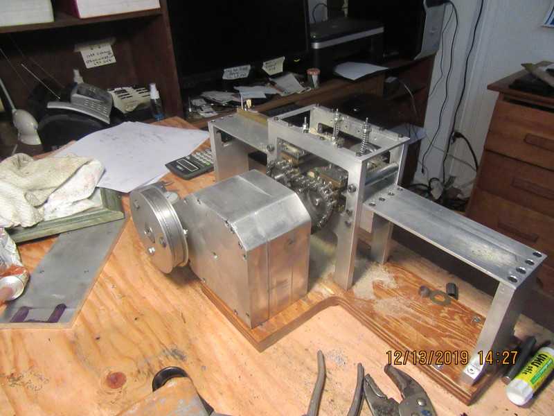
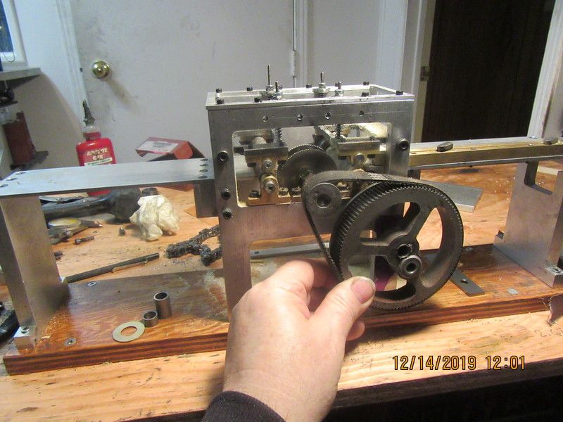
Now that the gear reducer has been completed, it's time to go around to the other side of the edger and spend some time on the final drive for the saws. I had one set of timing gears and pulleys that were salvaged off some appliance, and they will be the only timing belt drives used on the project. The new reducer has one shaft that extends completely through the leg of the edger to drive the saw blade, and I have to do some very serious calculating to make sure the hole gets put into the correct place. I have ordered two Lovejoy couplings. One will go between the engine and the clutch, and one will go between the clutch and the gear reducer. No O-rings or pulleys will be used at all.
YNpAXX.jpg
 
Back
Top