Needle Valve Magic

Home Model Engine Machinist Forum

Help Support Home Model Engine Machinist Forum:

This site may earn a commission from merchant affiliate links, including eBay, Amazon, and others.

Brian Rupnow

Design Engineer
Project of the Month Winner
Joined
May 23, 2008
Messages
15,250
Reaction score
8,532
Location
Barrie, Ontario, Canada
As most of you will know, I am a semi retired design engineer who builds model steam and gasoline engines. I have to publicly admit that while I am a fair hand at most things technical, I am a miserable failure at making needle valves for miniature carburetors. My lathe it too big to start with. Its a 10" x 18" lathe, and the chuck won't even close up small enough to hold a #2-56 screw (which most model carb needle valves seem to have as their main diameter.) I have to hold a smaller chuck (reclaimed off a dead electric drill) in my lathe chuck to even hold the screw. My 3 jaw chuck has about .003 runout in it, which I can live with, but it doesn't help. I sharpen my own HSS lathe bits, but still, trying to cut a 30 degree included taper on something that was only .085" diameter to start with has always eluded me. I have filed them. I have used fine emery paper on my flat file to dress them after filing. I have tried various Dremel type tools to grind them. I have held the screw in my electric drill and spun it against a revolving grindstone. All of this "Sort of" works. Then there are the people who advise that I should drill a .040" hole full length of a #2-56 screw and solder a darning needle into the hole. HAH!!! That trick is somewhat akin to trying to shove a dew worm up a wildcats---Oh never mind. It was only recently brought to my attention that THERE IS A BETTER WAY!!! Instead of trying to put a fine point on an a threaded screw which then screws INTO something else, what if the something else had an external thread and the needle valve actually did incorporate a darning needle soldered into a LARGER DIAMETER part which has an internal thread.--I know, kinda hard to visualize, but a picture is worth a thousand words. This is not my original idea. It is someone elses. I have created the attached 3D model, and what you see is a "section view" thru the carburetor, which clearly shows what I am blathering on about. I'm going to build this---Right Now. It seems like such a wonderful solution. I will post pictures and describe what I am doing as I progress. This one single "How to" could advance the art/craft of building succesful small i.c. engines at least a thousand years!! If it works the way it is supposed to, I will brag about it to you. If its a miserable flop (Like some things I have posted about) I will tell you.---Stay tuned!!!
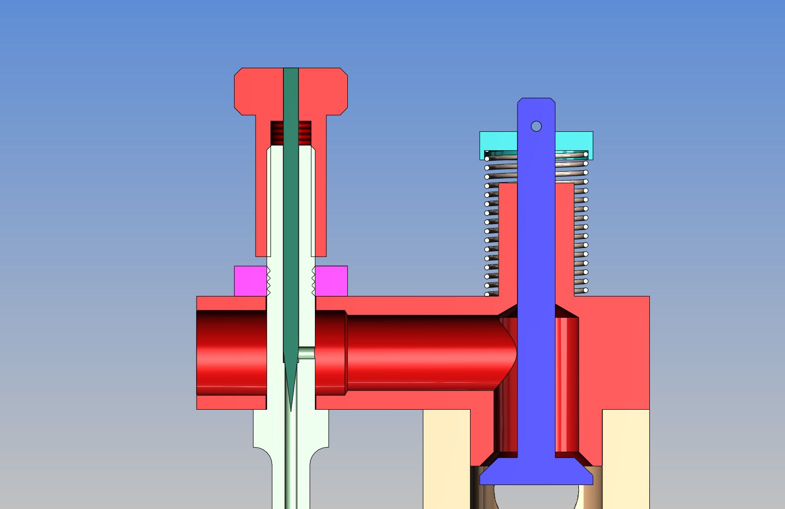
CARBURETOR-SUBASSEMBLY-NEWNEEDLEVALVE_zpse4d043b7.jpg
 
Brian,
A long time ago I put some information about needles in the downloads section. You might find it useful when shopping for needles. Here is a link to it.

Sewing needle diameters and notes

Gail in NM

 
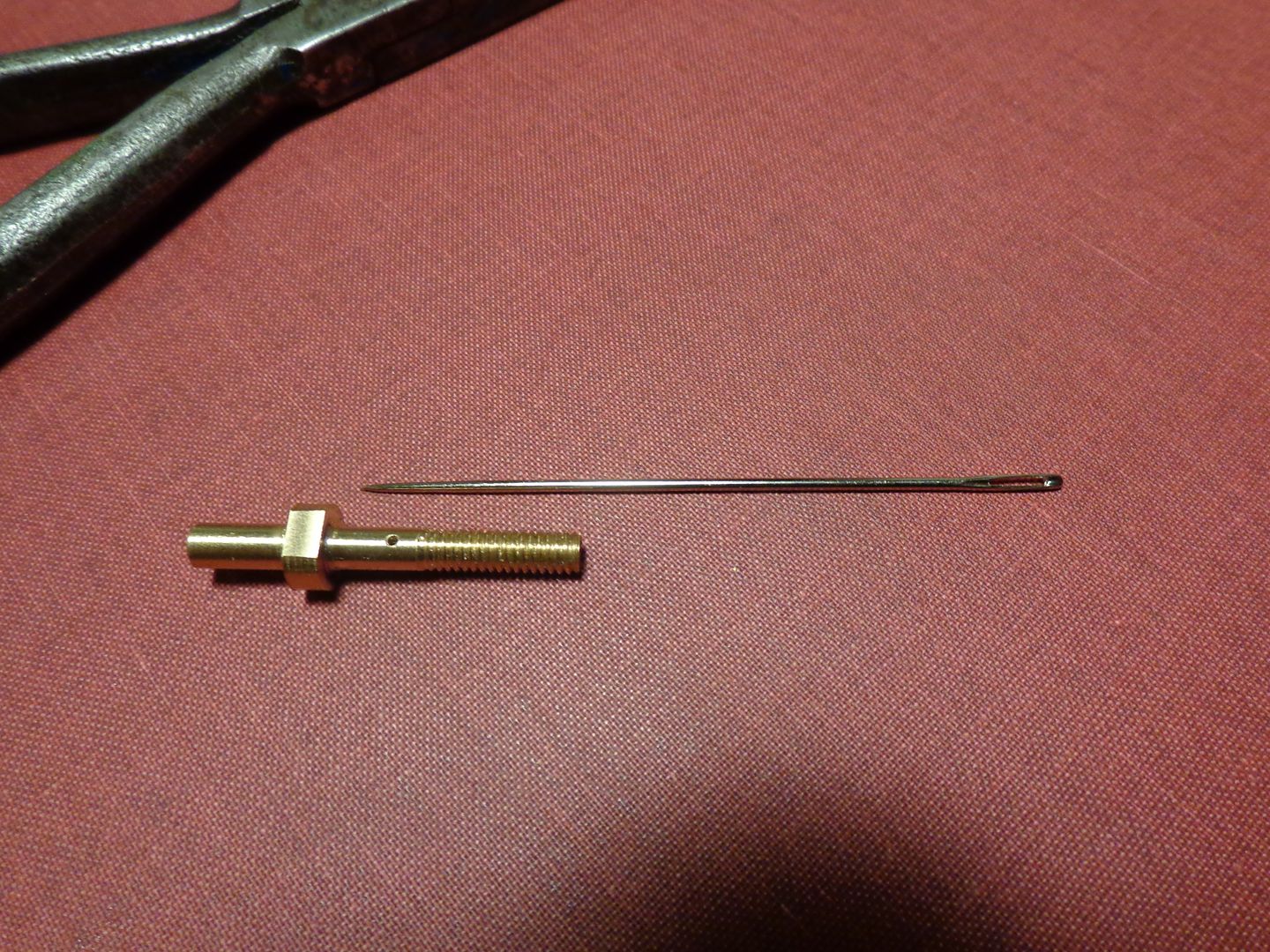
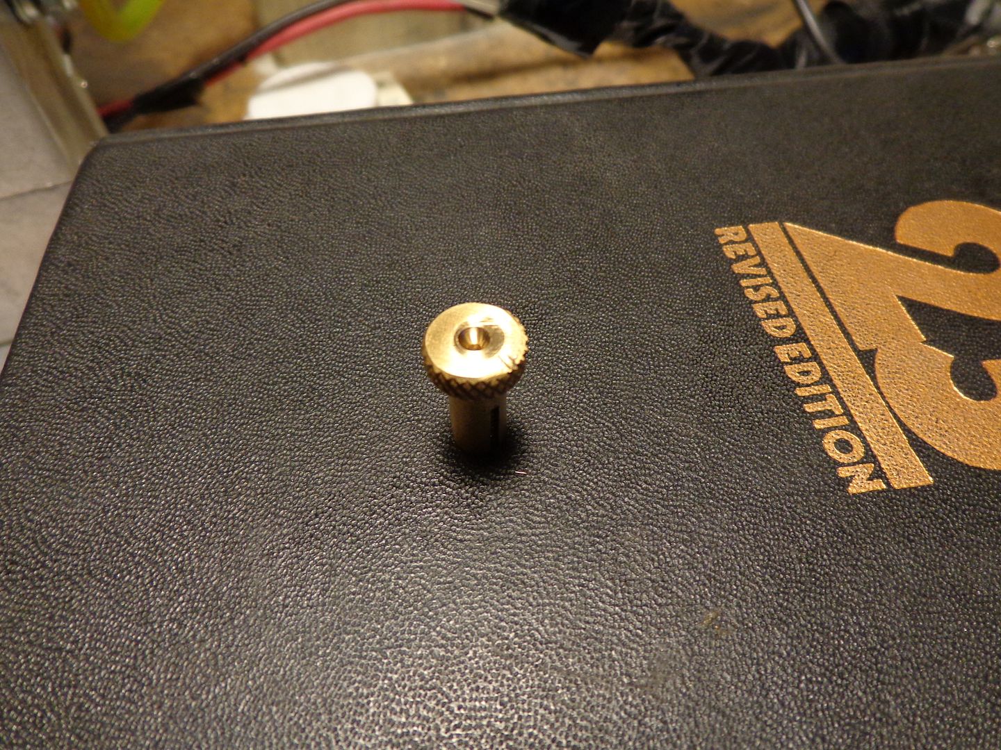
Guido---The reduction in diameter in the red part (air intake) provides enough venturi effect to lift the fuel 1 to 2" from the tank. I know it works because what I have shown in the solid model is what I am currently running . The only difference is the needle. the red "handle" at the top of the needle and the pale green "spray bar" the needle point goes into. I have just finished the new spray bar. It looks exactly like the old spray bar I am currently running, except the threaded end is 1/4" longer, the thread on the outside is longer by 1/4" as well. and the internal #2-56 threads are not there. The part in the picture in this post is what you see in the solid model. that humongous needle you see beside it is actually .048" diameter x 2 3/4" long. It will be cut off like the grey needle in the solid model when I get the next part (the red "handle for the needle) finished.
NEWSPRAYBAR001_zpsc8a3632c.jpg
 
MikeN--As I said in the very first post, I've tried that method, and it works---sort of. I currently have running engines that were done exactly that way. I am striving for something better here. Gail---Thank you. I remember your post about needles, in fact I used it 3 years ago when i was building one of my other i.c. engines to purchase a package of needles of the correct size. Alas, I was unable to ever drill the required hole for them, so the pack of needles has resided in my "small parts bin" ever since. The needle you see in the previous post is one of them.---Brian
 
Hi Brian,
I don't know if you are aware of it but I described a method of producing the points on needle valves on the Super Tigre thread - post 144> http://www.homemodelenginemachinist...g32-1cc-diesel-5cc-version-17674/index15.html

I have made many needles using this technique which have proved to give fine and sensitive control.
Re the use of sewing needles and not being able to find a drill suitable then the needle itself could possibly be turned into a reamer as shown for the piano wire.

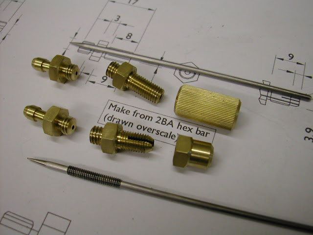
For needles which have an external thread on the needle itself I have used 8 and 7BA threaded rod drilled and reamed in the same manner for .048 and .060 piano wire ....
DSCN3197.JPG


Don't know if this will help any - certainly not intending to teach granny here ;)

Regards - Ramon
 
  • Like
Reactions: gus
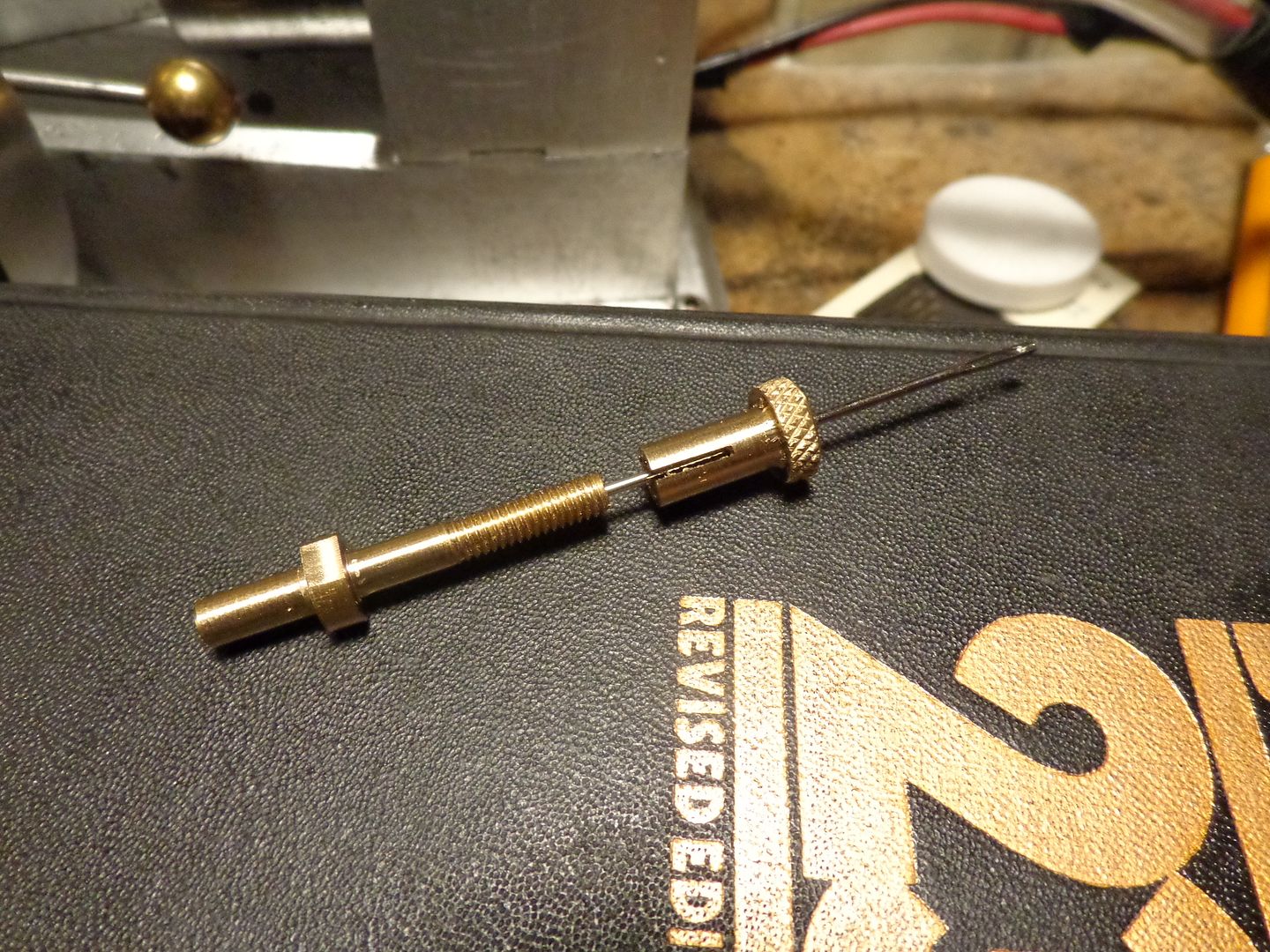
And here we have the second part of the magic needle trick. Now according to the book "The Shop Wisdom of Philip Duclos" here's what happens next. I shove the needle down into the spray bar untill it won't go any farther, which should mean it is totally shutting off any fuel that wnats to come up the spray bar from the fuel line (which is hooked to the other end of the spraybar when all is together.) Then I screw the knurled part onto the spray bar and screw it down on the thread until it bottoms out. (The knurled part has an 8-32 internal thread to match the 8-32 external thread on the spraybar.) Then I back the knurled part off one full turn, which on an 8/32 thread is 1/32". Then------Drumroll please----I solder the needle to the knurled part at the top where the needle exits, and grind off any of the needle that is left sticking out. The split in the knurled part is there so that the body of the knurled part can be "squeezed in" a bit with a pair of pliers. This prevents vibration from the running engine from unscrewing things and changing the setting. Sure is a nifty trick if it works.
SECONDPART-NEEDLETRICK001_zpsab9c9081.jpg
 
Ramon--I hadn't seen your post, but it appears to be basically the same as I have posted except you are not using a needle. It wasn't that I couldn't find a suitable sized drill that was my problem It was trying to drill such a small diameter hole full length of a #2-56 bolt that was my undoing. I had never seen this method I have just posted about before, until I read the Philip Duclos book.
 
Brian, this is a typical modern model engine needle. http://www3.towerhobbies.com/cgi-bin/wti0001p?&I=LXVBC6&P=7

The needle installed in an internally threaded carrier is also used by model engine manufacturer YS and others, but with a ratchet spring. Model engines of one type or another have used the slotted and pinched idea probably since the beginning. This particular engine was built in the mid to late 1950's.


I guess spending a lot of time looking at model engine designs I've seen a lot of different ideas. The other one that I've heard of but haven't tried is the flat needle. These were used by Fox engines in the US some time ago. http://modelenginenews.org/cardfile/images/fox35_02.jpg

Greg
 
  • Like
Reactions: gus
Using my smallest center drill (#1) I machine a small divot in the top of the knurled piece. That is so that after the needle is cut off and filed flush, I will still have sufficient solder to hold the back end of the needle solid. I don't like to have a "lump" of silver solder stuck up on top of that knurled wheel.
CENTERDIVOT002_zpsfb2ba236.jpg
 
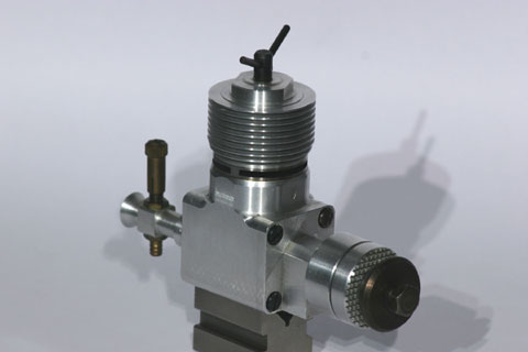
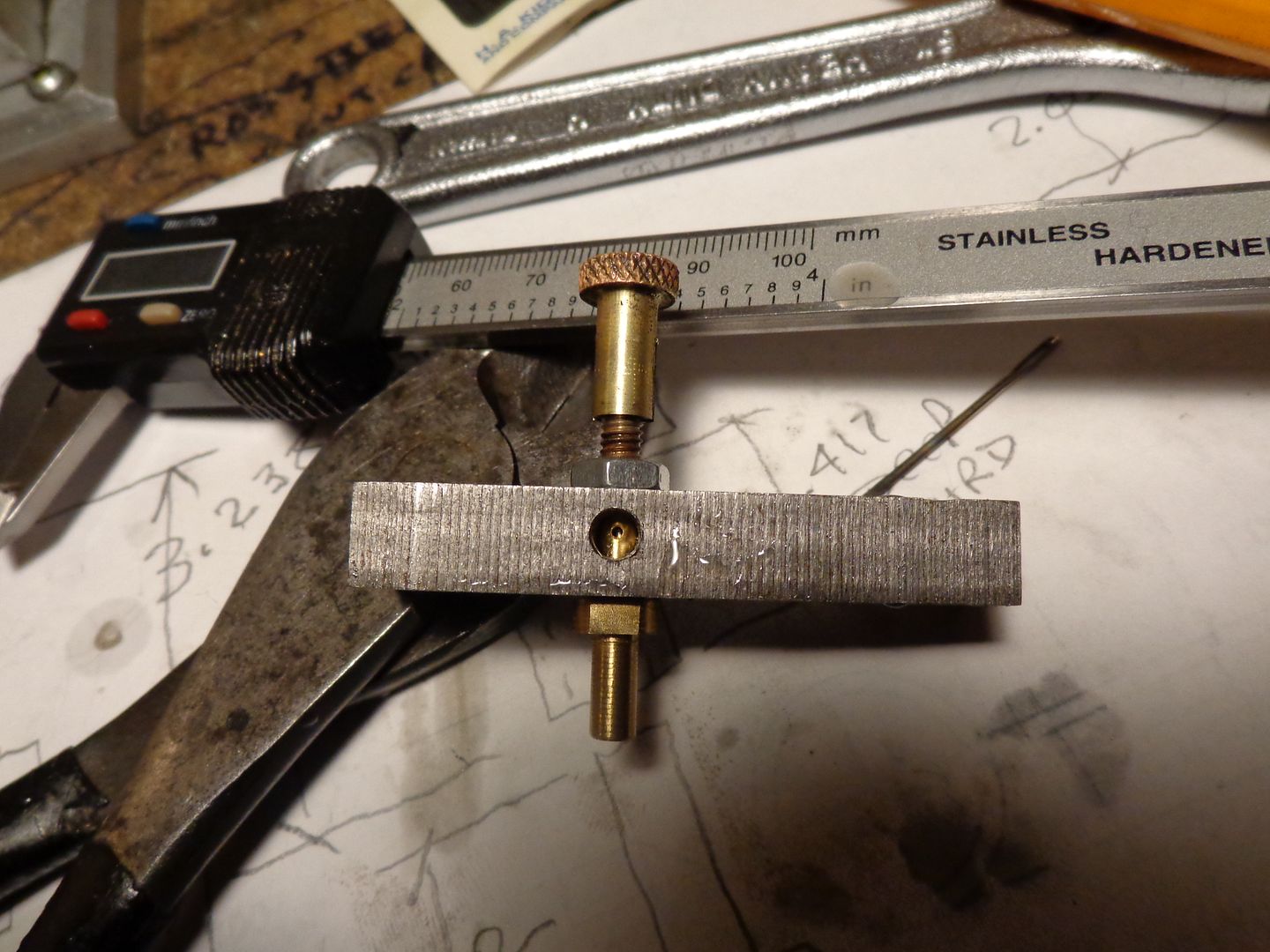
There it is, finished as it gets. I assembled the whole thing to a block of scrap steel the same thickness as the carburetor air horn that it fits into just to avoid any "after the fact" surprises. I soldered the needle in place and cut off the excess end.This thing is absolutely airtight when blown on from the fuel line end, and seems to have an amazing long range of adjustment untill it is "wide open"----Very unlike any needle valves I have made prviously, which seemed to be about one turn from totally open to totally closed. If you look close at the solid model, you will see another very neat trick This whole spray bar and needle valve assembly just fits thru a hole drilled in the air horn and is locked in place by a hex nut. NO SOLDERING REQUIRED!!! When I assembled it to the air horn on the first go round, I put a little liquid "seal all" compound around the entrance and exit to keep it from sucking any air. My next stop in this journey is to install this on the carburetor and try it out.
MAGICNEEDLEFINISHED001_zps36fd4231.jpg
 
  • Like
Reactions: gus
If working with a ferrous metal you can make a device to turn needles on center. Make a v block, mill a slot perpendicular to the v. Place a small pulley on the shaft of the needle to be turned. Find a suitable motor with a matching pulley to turn the needle. The belt must pull against the needle to be turned forcing it into the v. The pulley should be located in the center of the slot cut earlier and a bracket added to hold the motor to the back of the v block. By using a flat fine honing stone you can then spin the shaft and use the stone to form the needle. The v block could also be used along with a grinder to get the same results.

Has anyone tried turning the hole to face perpendicular to the flow of air?
 
Has anyone tried turning the hole to face perpendicular to the flow of air?

Yes, I have, not much different on my JD ?
 
Id really like a nice set of carb plans for my webster build, something with a throttle. I havent tried to grind a needle valve yet, but I think its only half the battle....Keeping an eye on this thread for sure....
 
Hello,
I have used old style phonograph needles for needle valves, I lock-tite it in place.
Alec Ryals
 

Latest posts

Back
Top