You are using an out of date browser. It may not display this or other websites correctly.
You should upgrade or use an alternative browser.
You should upgrade or use an alternative browser.
Maryak 10
- Thread starter Maryak
- Start date

Help Support Home Model Engine Machinist Forum:
This site may earn a commission from merchant affiliate
links, including eBay, Amazon, and others.
Maryak
Well-Known Member
- Joined
- Sep 12, 2008
- Messages
- 4,990
- Reaction score
- 77
Hi Dave,
Thanks for your concern about my chompers. I think it's going to be a long and involved saga.
Yes I am going for a lap fit. After the gudgeon is finished I intend to mate the piston and cylinder.
After a bit of thought I am now opting for a semi floating gudgeon with the pin locked to the conrod. It should save trying to machine circlip grooves in the piston and I need not have bushed the gudgeon end but hey this is experimental so why not ???
Best Regards
Bob
Maryak
Well-Known Member
- Joined
- Sep 12, 2008
- Messages
- 4,990
- Reaction score
- 77
Yesterday was a public holiday here for the Adelaide Cup so nothing on the model front.
Below is today's effort.
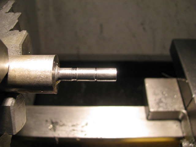
Parting off the gudgeon pin.
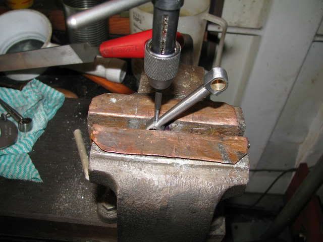
Tapping the conrod for the gudgeon pin locking screw.
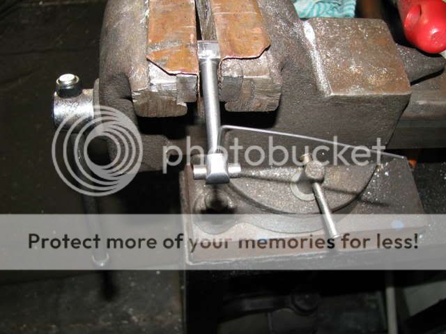
The gudgeon pin in the locked position.
A mandrel to hold the piston for lapping
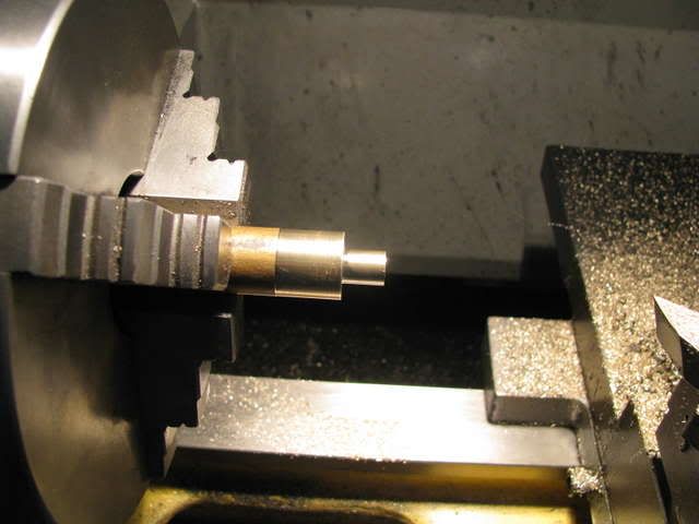
Bronze for the piston lap.
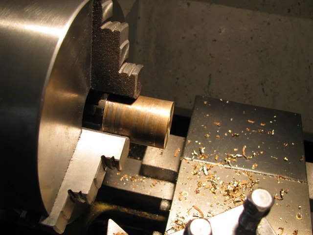
Lapping the piston.
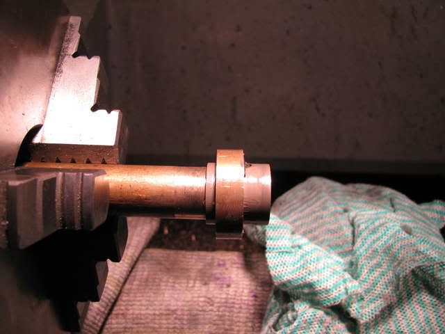
A trial assembly.
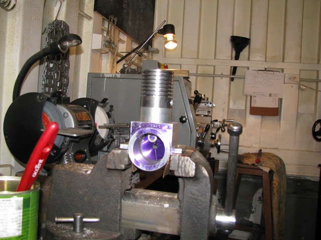
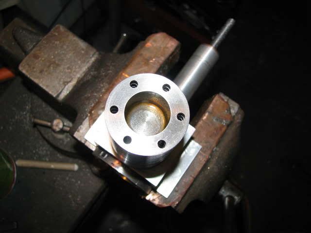
Below is today's effort.
Parting off the gudgeon pin.

Tapping the conrod for the gudgeon pin locking screw.

The gudgeon pin in the locked position.

A mandrel to hold the piston for lapping

Bronze for the piston lap.

Lapping the piston.

A trial assembly.


Seeing the engine chucked in the vise next to the paint can made me realize how big this build is. This is no Cox .049.
Looking good!
Looking good!

$99.99
AHS Outdoor Wood Boiler Yearly Maintenance Kit with Water Treatment - ProTech 300 & Test Kit
Alternative Heating & Supplies

$89.99
Outdoor Wood Boiler Water Treatment Rust Inhibitor- AmTech 300 & Test Kit
Alternative Heating & Supplies

$94.99
$109.99
AHS Woodmaster 4400 Maintenance Kit for Outdoor Wood Boiler Treatment
Alternative Heating & Supplies

$39.99
$49.99
Sunnytech Low Temperature Stirling Engine Motor Steam Heat Education Model Toy Kit For mechanical skills (LT001)
stirlingtechonline

$45.99
Sunnytech Mini Hot Air Stirling Engine Motor Model Educational Toy Kits Electricity HA001
stirlingtechonline

$29.95
Competition Engine Building: Advanced Engine Design and Assembly Techniques (Pro Series)
Amazon.com Services LLC
![DreamPlan Home Design and Landscaping Software Free for Windows [PC Download]](https://m.media-amazon.com/images/I/51kvZH2dVLL._SL500_.jpg)
$0.00
DreamPlan Home Design and Landscaping Software Free for Windows [PC Download]
Amazon.com Services LLC

$519.19
$699.00
FoxAlien Masuter Pro CNC Router Machine, Upgraded 3-Axis Engraving All-Metal Milling Machine for Wood Acrylic MDF Nylon Carving Cutting
FoxAlien Official

$40.02
$49.99
Becker CAD 12 3D - professional CAD software for 2D + 3D design and modelling - for 3 PCs - 100% compatible with AutoCAD
momox Shop

$24.99
$34.99
Bowl Sander Tool Kit w/Dual Bearing Head & Hardwood Handle | 42PC Wood Sander Set | 2" Hook & Loop Sanding Disc Sandpaper Assortment | 1/4" Mandrel Bowl Sander for Woodturning | Wood Lathe Tools
Peachtree Woodworking Supply Inc
deere_x475guy
Well-Known Member
Good eye Steve I didn't even notice that. Looking great Maryak and thats for the pics...
- Joined
- Jun 4, 2008
- Messages
- 3,294
- Reaction score
- 636
Newbie question on gudgeon (wrist) pins in general. Since you have a lock screw it is evident that as the piston moves the pin must oscillate in the side walls of the piston. Should I assume that the bronze of the piston acts as bushings?
On my smaller CO2 engine, the plan has the piston rods moving over a stationary gudgeon. I am wondering if there will be a problem with the piston rod walking sideways. If so, I imagine I could make some brass bushings to keep it in the center. Thoughts? FWIW the diameter of the pistons is 3/4". The wrist pin is 1/8" diameter rod (could be drill rod or brass).
On my smaller CO2 engine, the plan has the piston rods moving over a stationary gudgeon. I am wondering if there will be a problem with the piston rod walking sideways. If so, I imagine I could make some brass bushings to keep it in the center. Thoughts? FWIW the diameter of the pistons is 3/4". The wrist pin is 1/8" diameter rod (could be drill rod or brass).
Yes Steve makes a great point.......WHEN it starts Bob ;D.....make sure we don't end up calling you "fingers", as I assume your putting a prop on the front of that beast?
Knowing something of your past endevors....I have every reason to believe that won't happen....you've been around big stuff far to long to be careless now!
Dave
Knowing something of your past endevors....I have every reason to believe that won't happen....you've been around big stuff far to long to be careless now!
Dave
Maryak
Well-Known Member
- Joined
- Sep 12, 2008
- Messages
- 4,990
- Reaction score
- 77
Steve and the other Bob,
Thanks guys for your continued interest and support. :bow: :bow: Yep, bigger than Ben Hur. ;D
Kvom,
1 Above, yes the gudgeon/wrist pin oscillates in the piston. In this case 316SS against t200 cast iron. I was originally aiming for a fully floating setup with circlips to prevent sideways movement of the pin. I settled for the above as being far easier to machine and secure. I need not have placed a bronze bush in the gudgeon/wrist pin end of the conrod with the method I ended up with.
2 Above, your mechanism is the 3rd option of those used for conrod oscillation. Maybe you could lock the pin with a screw from the underside of the piston. Maybe you could shorten the pin a little and fill the ends with soft solder. Last but not least, if your piston has rings one of the latest innovations, (12":1ft), is to put aluminium end caps on the pin which if it moves pushes the aluminium against the cylinder wall. Can't say I'm all that thrilled about the idea but it's out there working so there must be something to it.
And..... thanks for your support and Interest. :bow:
Thanks Dave, :bow: I've broken a few on the way by dropping boiler doors on them, (just as well I'm not a concert violinist : ), but I've managed to keep all my digits, (all 21 of them).

I think attempting to run this thing will be an outside job with a substantial mounting block and a couple of bloody great clamps.


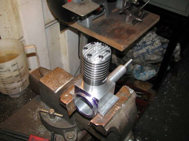
Below is today's effort.
Some Aluminium for the cylinder head.
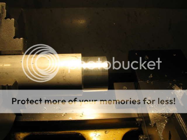
Reaming the centre hole for the compression screw plug.
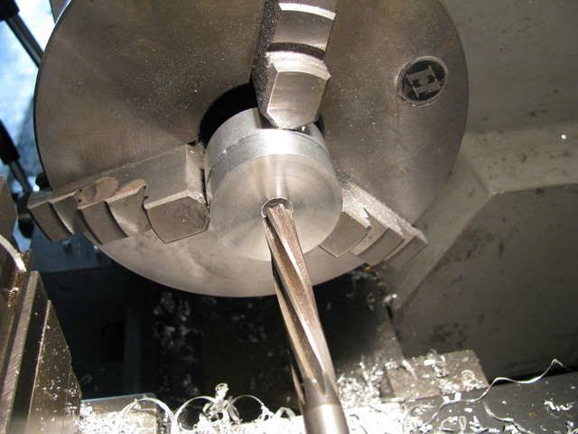
Drilling for the head bolts.
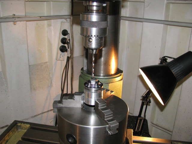
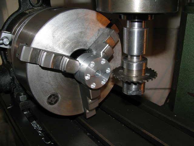
Set up for machining the cooling fins.
Last but not least, I finally received my Xmas present from my daughter, (its' been on back order).


Now I will have to expend extra energy and impose self discipline to finish M10 before delving into gas engines and electrics.

Thanks guys for your continued interest and support. :bow: :bow: Yep, bigger than Ben Hur. ;D
kvom said:Newbie question on gudgeon (wrist) pins in general. Since you have a lock screw it is evident that as the piston moves the pin must oscillate in the side walls of the piston. Should I assume that the bronze of the piston acts as bushings?
On my smaller CO2 engine, the plan has the piston rods moving over a stationary gudgeon. I am wondering if there will be a problem with the piston rod walking sideways. If so, I imagine I could make some brass bushings to keep it in the center. Thoughts? FWIW the diameter of the pistons is 3/4". The wrist pin is 1/8" diameter rod (could be drill rod or brass).
Kvom,
1 Above, yes the gudgeon/wrist pin oscillates in the piston. In this case 316SS against t200 cast iron. I was originally aiming for a fully floating setup with circlips to prevent sideways movement of the pin. I settled for the above as being far easier to machine and secure. I need not have placed a bronze bush in the gudgeon/wrist pin end of the conrod with the method I ended up with.
2 Above, your mechanism is the 3rd option of those used for conrod oscillation. Maybe you could lock the pin with a screw from the underside of the piston. Maybe you could shorten the pin a little and fill the ends with soft solder. Last but not least, if your piston has rings one of the latest innovations, (12":1ft), is to put aluminium end caps on the pin which if it moves pushes the aluminium against the cylinder wall. Can't say I'm all that thrilled about the idea but it's out there working so there must be something to it.
And..... thanks for your support and Interest. :bow:
steamer said:Yes Steve makes a great point.......WHEN it starts Bob ;D.....make sure we don't end up calling you "fingers", as I assume your putting a prop on the front of that beast?
Knowing something of your past endevors....I have every reason to believe that won't happen....you've been around big stuff far to long to be careless now!
Thanks Dave, :bow: I've broken a few on the way by dropping boiler doors on them, (just as well I'm not a concert violinist :
I think attempting to run this thing will be an outside job with a substantial mounting block and a couple of bloody great clamps.


Below is today's effort.
Some Aluminium for the cylinder head.

Reaming the centre hole for the compression screw plug.

Drilling for the head bolts.

Set up for machining the cooling fins.

Last but not least, I finally received my Xmas present from my daughter, (its' been on back order).


Now I will have to expend extra energy and impose self discipline to finish M10 before delving into gas engines and electrics.

Loving this project and now can't wait to see your next! :bow: I've always wanted to do a hit & miss engine. Only problem with this site is I'm always looking at everybody elses wonderful projects when I should be in the garage working on my own! ???
Nick
Nick
Maryak
Well-Known Member
- Joined
- Sep 12, 2008
- Messages
- 4,990
- Reaction score
- 77
Nick,
Don't say that ;D I'm having enough trouble containing myself as it is and it has only been 18 hours. :
Phil,
The bolts holding the cylinder to the head are 5/32" x 2 3/4" long - 6 off and the cylinder OD is 1 5/8".
Thanks to both you and Nick.
Best Regards
Bob
Don't say that ;D I'm having enough trouble containing myself as it is and it has only been 18 hours. :
Phil,
The bolts holding the cylinder to the head are 5/32" x 2 3/4" long - 6 off and the cylinder OD is 1 5/8".
Thanks to both you and Nick.
Best Regards
Bob
Metal Mickey
Well-Known Member
- Joined
- Jul 5, 2008
- Messages
- 612
- Reaction score
- 6
Bob great stuff. Have you chained down your container for when it starts? Also there is the problem of Australia actually moving towards New Zealand or are you facing towards the Philippines? You could give a whole new meaning to continental drift! :big: :big:
Good work though! :bow:
Good work though! :bow:
Hi Bob
I just checked the stats on this thread before reading the latest update, 7400 views, you sure do capture many peoples interest when you are posting. I really enjoy catching up with your progress and the way you document everything with great pictures, very much appreciated. Keep up the great work.
Kind regards
Malcolm
Maryak
Well-Known Member
- Joined
- Sep 12, 2008
- Messages
- 4,990
- Reaction score
- 77
Thanks Guys, :bow: :bow: :bow: :bow:
Enjoyed all the comments :big: :big:
It's probably suffering from an overdesign problem as far as power/weight ratio is concerned. I intend to make a starter out of a rubber door stop which will fit my electric drill and keep me and my fingers a safe distance away - just in case it starts.
Nil report for yesterday as I spent some time watching the pour of our foundations, (see Mrs Maryaks Mansion).
Best Regards
Bob
malcolmt said:I just checked the stats on this thread before reading the latest update, 7400 views, you sure do capture many peoples interest when you are posting. I really enjoy catching up with your progress and the way you document everything with great pictures, very much appreciated. Keep up the great work.
Exactly. While this kind of engine isn't necessarily my cup of tea, the excellent documentation of the build is. It's a self contained how-to. He could be making just about anything, and I'd still follow along.
Similar threads
- Replies
- 117
- Views
- 42K


