Make a 72 tooth worm gear without indexing?

Home Model Engine Machinist Forum

Help Support Home Model Engine Machinist Forum:

This site may earn a commission from merchant affiliate links, including eBay, Amazon, and others.
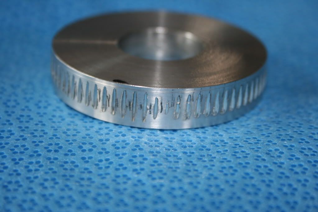
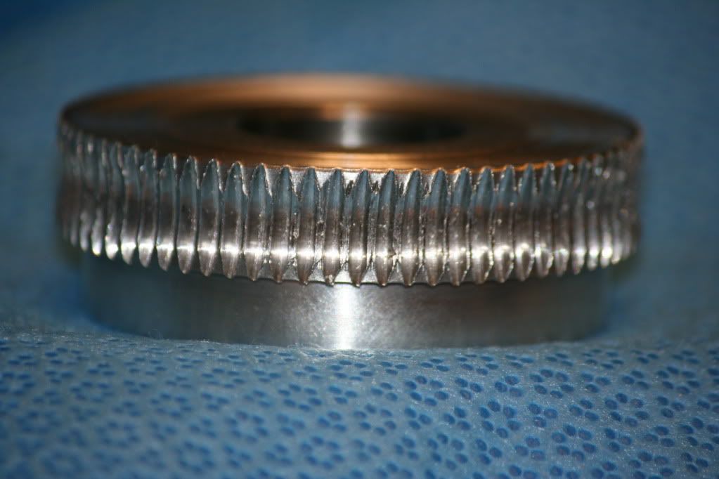
This is where is the gnashed teeth joined at one revolution. Looks pretty good, huh?
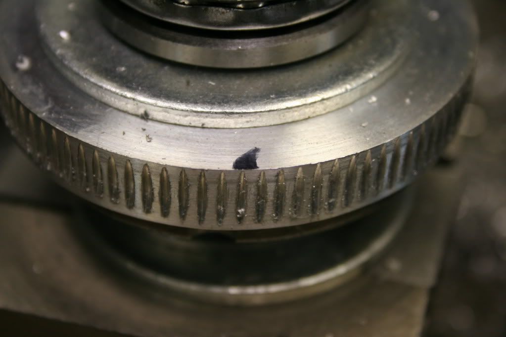
IMG_4357_zps59bf1f4e.jpg


And after forming with the full tooth portion of the hob.
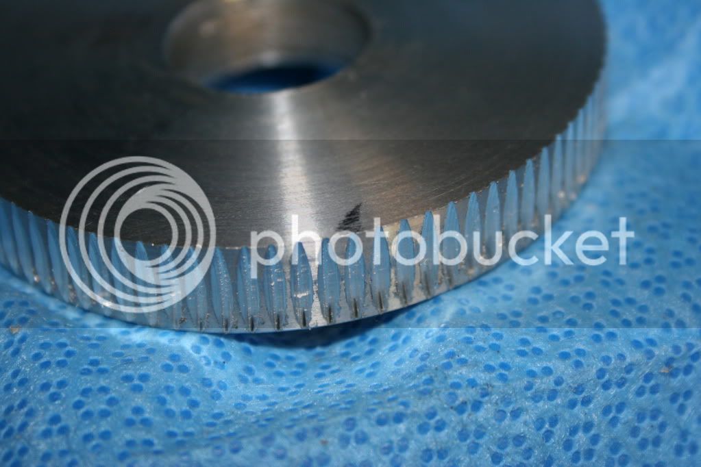
IMG_4358_zpsd134636d.jpg


I'm very happy with these results, but the tooth count is not as predicted. The measured diameter is for 90 teeth, which gave an 88 tooth count for chipenter. How about 93, Bunkie? This is pretty consistent with my previous experience, which was two excess teeth. I think I will try making the diameter for 70 teeth and see what happens.

Bill
 
Turned the blank to 2.228", which is the calculated diameter for a 70 tooth gear. Here is the result:

IMG_4359_zpsc8053991.jpg


The short gnash is the start of the 72 nd tooth. Almost perfect. The gnashes were made by cranking in .050" after making solid contact with the hob. By solid, I mean unable to rotate the blank by hand.

This blank was a test mule and has some quality issues. A final gear will be made.

Bill
 
That link is of no value to a person wanting to make a worm gear without indexing.

Requires gnashing (what I'm avoiding)
No tooth calculation information (info I could have used)
Says to use bearings to support the gear blank (not needed)
Calls for hardening of hob. (not needed)
Contains improper hobbing instructions for hobbing a given number of divisions.

I say that in order to prevent confusion by anyone deciding to use my method and should not be construed as a critcism of anyone.

Here is a summary of my technique:

Make sure the hob flute width is no more than 1/2 the length of the tooth to be produced on the gnashing pass.

Make gnashing pass as deep as possible. I fed the blank into the hob the full depth (.050") while rocking the hob back and forth while located over a flute. After depth of cut is established, lathe power can be used.

Make only one pass with the gnashing hob in order to leave material for the finish hob to smooth any irregularities.

Use several passes of the finishing hob to allow it to work out any imperfections.

A greased piece of steel nearly the diameter of the blank makes an adequate surface for the blank to rotate against.

It was necessary to use an upper bearing surface in order to prevent gear "lifting".

I used WD 40 to lube the blank and wire brushed like crazy to control chip build up.

Use chipenter's instruction for calculating blank diameter, only subtract 2 teeth, not add. I think he got confused as he crossed "The Pond":D. In my case: 70 divided by 10, divided by Pi was perfect.

Use aluminum. I have no idea of the forces that would have to be overcome while making the gear of brass. It may work, it may not, most likely dependent upon your lathe's rigidity.

Bill
 
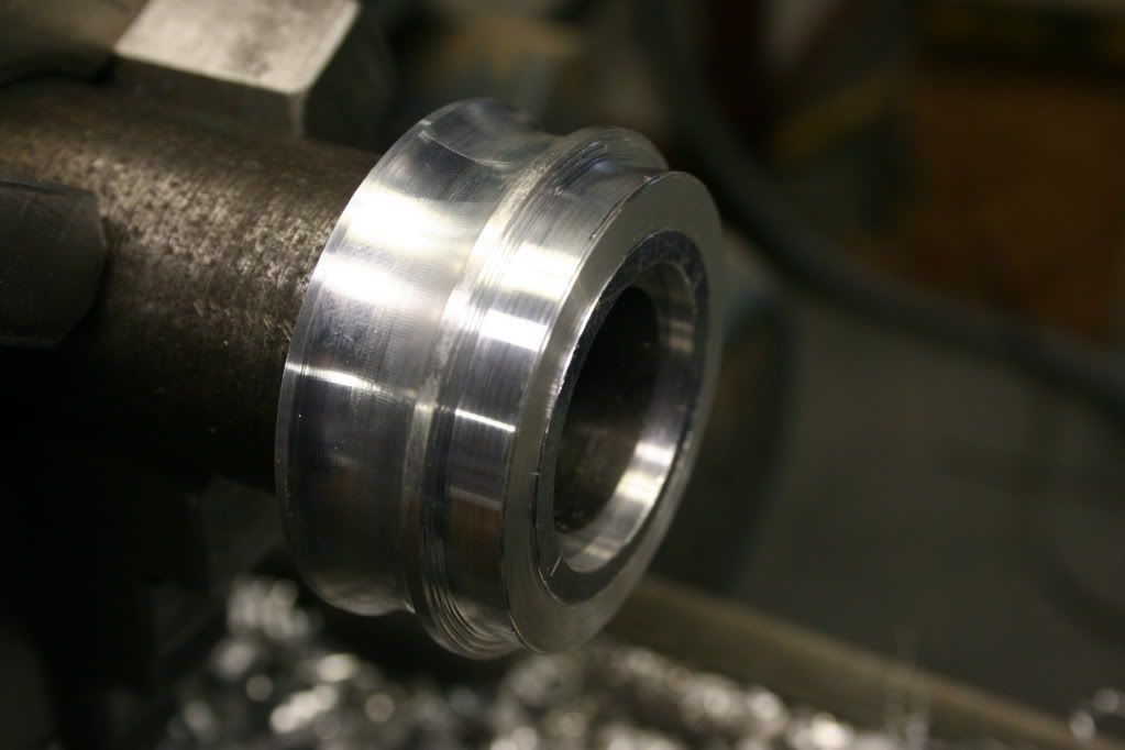
I decided it would be best to have a concave shape to the gear teeth, in order to maximize tooth contact and wear. So I made a fancy blank:
IMG_4394_zpsdb259e37.jpg


Problem: The tooth count went to 78 and tooth contact with worm is not good due to the decreased tooth spacing.
IMG_4412_zps16a6ddf9.jpg

Tooth spacing is 11.4 tpi instead of 10. I cannot make an 8.5 tpi hob, has to be either 8 or 9. Any ideas how well a gear made with an 8 tpi hob (probably would give 9.5 tpi) would mesh with a 10 tpi worm?

Any other suggestions, other than to forget the concave teeth?

Bill
 
Just thinking out loud. While its true I cannot make an 8.5 tpi hob, I can make a 9.5 tpi worm, as well as 10, 11 and 12. So I'm debating the wisdom of making an 8 tpi hob and selecting the best pitch worm to mate with it.

Or should I just go with the flat face gear that I know I can make? Anyone really interested?

Bill
 
As I fiddled with the finished gears, I realized the tooth form was really bad. The hob had been made with a rather large flat bottom and small flats on top. Looking at the gears, especially the concave ones, it became apparent a totally different tooth pattern was needed. The space between the gears was lobbed out at the bottom and the teeth were short and sharp.

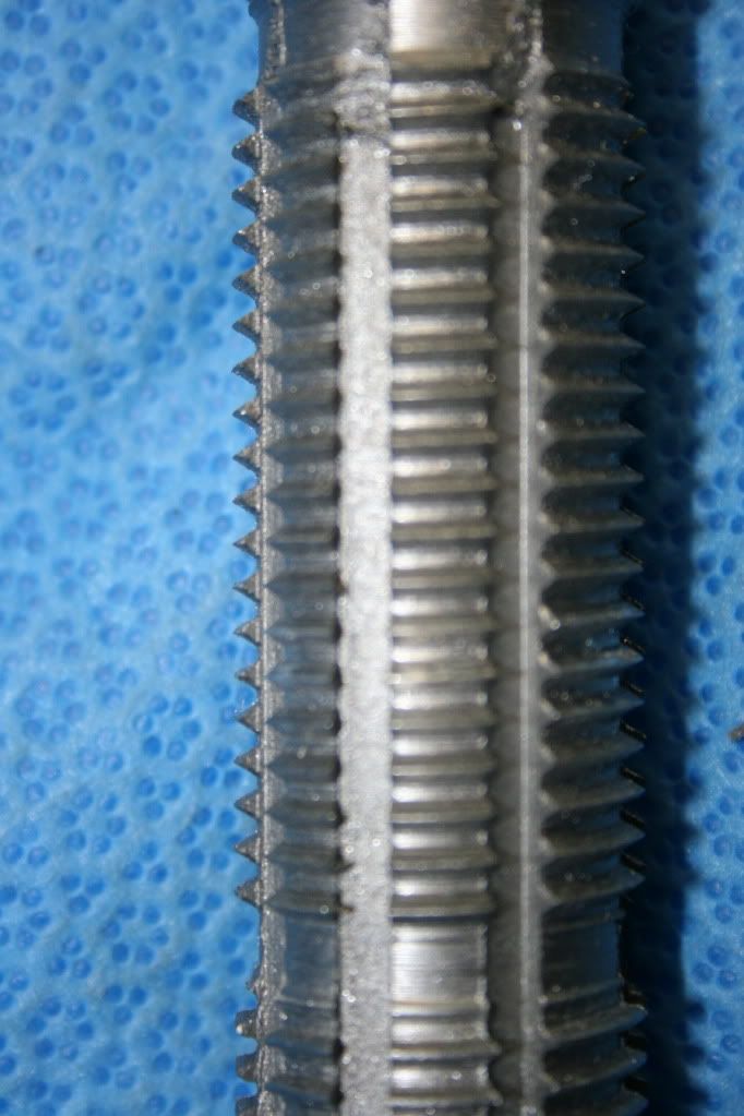
The best I could do was to make the hob wtih a wider Vee at the bottom of the thread and sharp on top. Here is a photo of the revised hob. If you look on the left side of the hob you can get a pretty good feel for what I ended with.

IMG_4413_zps60c593b1.jpg


This improved gear tooth enough that the 10 tooth worm would engage without slop on the concave gear. Previously a 13 tooth was required.

But I think I'm going to abandon the idea of concave gear. Don't think I will be able to wear out the flat gear, especially with the improved tooth shape. In addition, the concave gear is proving very difficult.

Time to move on.

Bill
 
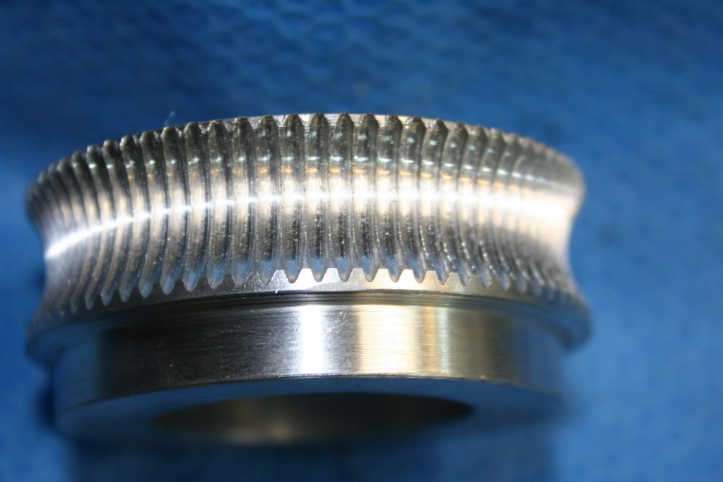
My "keeper" gear. Note the depth of tooth formation.
IMG_4414_zps50da8098.jpg


I had been afraid that if I went to deep, the change in pitch diameter would cause the hob to walk along the periphery, creating a new tooth count. Does not happen. The hob did create multiply patterns the first few times around the blank, but once it settled down, I never destroyed the pattern. The hob was fed into the blank about 40 thou farther than the previously posted completed gear. The two gears are the same width.

Bill
 
For what it's worth, I made some worm gears with a 1" 8 tap where the gear material was thinner then the flute by sandwiching the blank between two peaces of plastic to keep the cut constant. I also did one using wood on each side of the blank. Worked well for me. Carl
 
It's an old thread I know, but I thought to show how I made a wormwheel to be used in a startracker I designed.
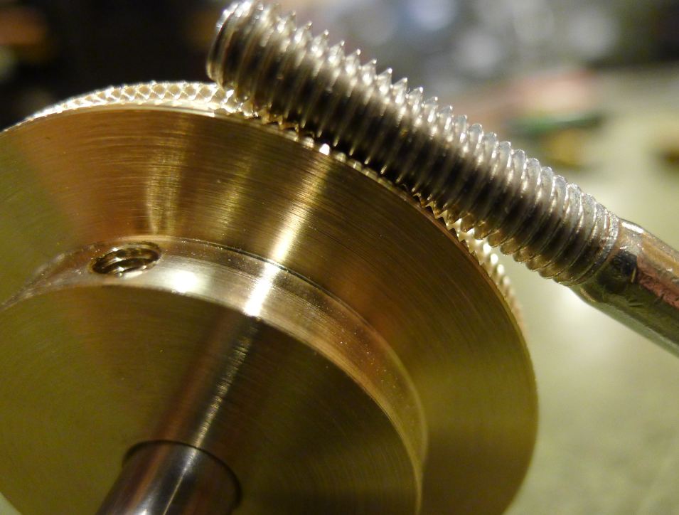
The assembly runs very slow, the wormwheel itself runs at a whoping1 rpday. So I choose SS for the worm. A SS bolt(M6) that has been cleaned up a bit serves as worm.
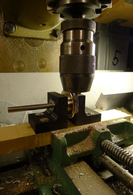
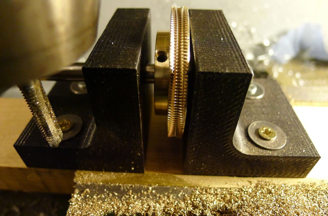
To make the wormwheel is basically nothing more than a M6 tap pushing against a brass's disk perimeter. I made(3D printed) two brackets that will hold two ball bearings(8x22x7). The wormwheel has the same size hole as the bearings. Once the assembly is fixed on the milling machine, the wormwheel can rotate freely around the 8 mm axis.
Then the rotating tap is pushed very gently against the perimeter of the wormwheel. If you go for it, again go slow..!
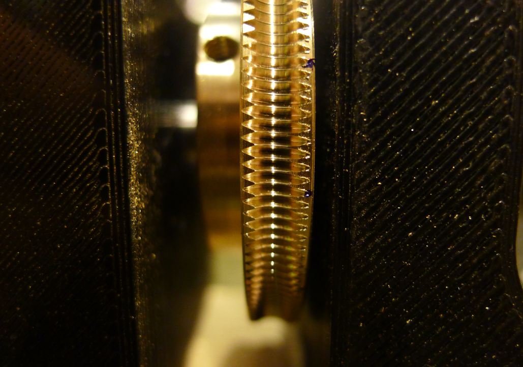
As you see there's no indexing involved, yet it turned out to be a perfect wormwheel, very sharp and clean teeth.

EDIT : forgot to mention diameter of the wormwheel : 50mm (2") Ratio : 1:156

wormwheel-02.JPG


wormwheel-03.JPG


wormwheel-04.JPG


wormwheel-05.JPG
 
The OP seemed to be asking how to generate a wheel with a chosen tooth count without any indexing.
He should have asked how to generate a wheel without understanding - without understanding that gashing (not gnashing :D ) using some form of indexing is the way to set tooth spacing and thus set tooth count ;-)
 
Hi Nick,
Just wanted to demonstrate a quick and easy way to make a rather good quality wormwheel.
Maybe I should have started a new thread for this one...;)
 
Having followed amateur telescope making since i was a kid, this is just another example of the get her done attitude in this group. Ive seen some amazing work from these dedicated hand builders of telescope hardware. Often this work is done in the most meager of shops.

Thanks for the post.
 
Hi Chriske,
Did you start with a plain disc with a flat edge or did you start with a groove with a diameter equal to the tapping drill size for an m6 thread?
Regards,
Alan C.
 
Hi Alan,

I started with a flat perimeter. It probably would work faster if I cut a groove first.
I'll need an extra set of these wormwheels for another project very soon, Maybe I'll try it.
On the other hand it's maybe not worth the effort because the teeth are not very deep for a M6 tap. It only takes me literal a few minutes to cut one wormwheel. I can imagine if I would cut a wormwheel with a very large tap, say M24(about 1"), it'll work way faster to have that groove first.

Chris
 
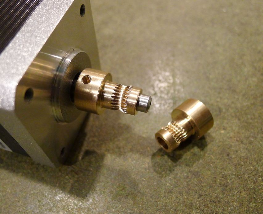
What puzzle me is the fact that using this technique I get a perfect wormwheel every time again, no matter what diameter the wormwheel is. I've tried this with smaller diameters to and every time I get a perfect result. Even with very small diameters. I even cut a wormwheel on a 8mm(about 1/3") smooth rod, to be used as a hobbed bolt in a 3D-printer. Perfect result, each time.
My brain says : the very first point were you start cutting on that perimeter is not necessarily going to meet exactly with the last cut on that perimeter after exactly 1 rotation. So I decided to challenge my brain and made a smaller wormwheel so I made a 49mm and a 48 mm and also a 45mm diameter wormwheel with that same M6 tap. Each time again I got a perfect result. And I can't still figure out why.

This is a 'wormwheel' I cut on a 7mm diameter smooth brass rod. Way to small for a wormwheel of course but a perfect hobbed bolt for a 3D-printer.
hobbed-bolt-7mm.JPG
 

Latest posts

Back
Top