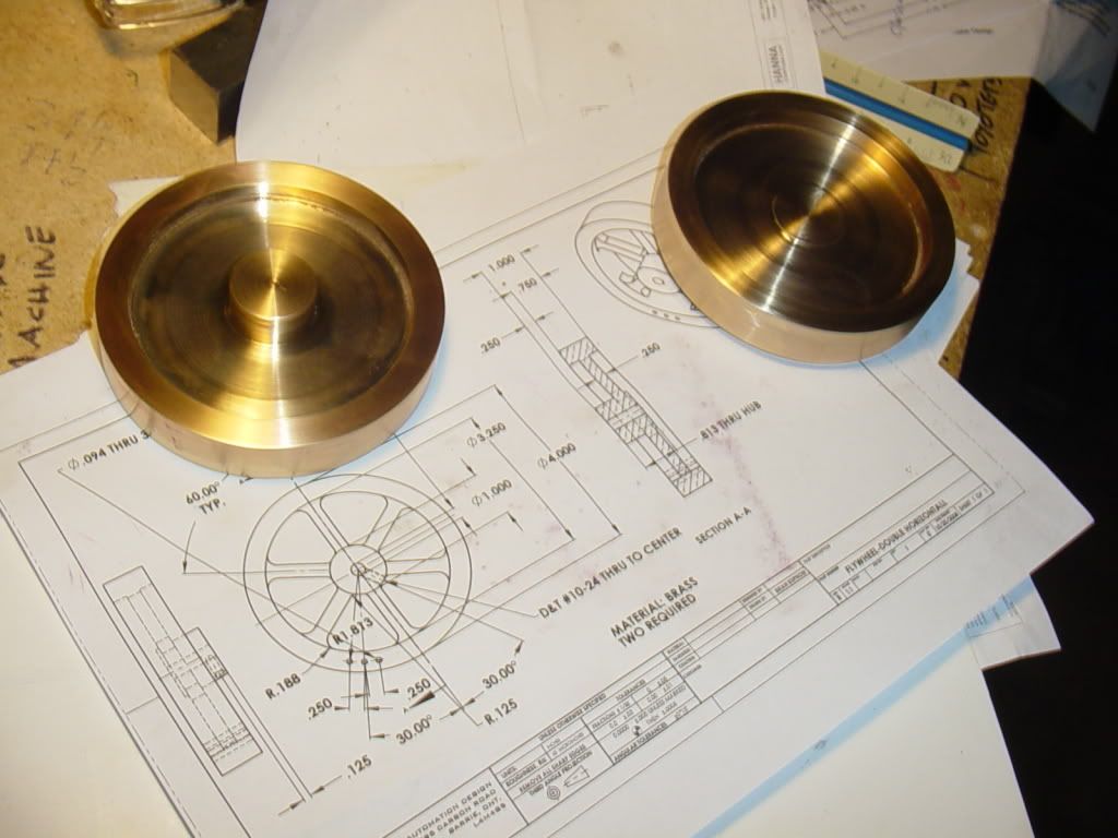
Machining flywheel "windows" with rotary table on mill

Home Model Engine Machinist Forum

Help Support Home Model Engine Machinist Forum:

This site may earn a commission from merchant affiliate links, including eBay, Amazon, and others.

Brian Rupnow

Design Engineer
Project of the Month Winner
Joined
May 23, 2008
Messages
15,250
Reaction score
8,529
Location
Barrie, Ontario, Canada
At some point later today I will be doing my first set-up on the rotary table to machine "windows" in a spoked flywheel. There seem to be a number of ways to do this, one of which is to drill all the corner holes first, in all the windows, then use the rotary table to rotate the part and let an end mill cut arcs between the outer holes and between the inner holes. then traverse the bed to cut the straight sides of the windows. I an exploring a second option that involves drilling fewer holes. Since my flywheels have 6 equally spaced spokes (and 6 equally spaced windows). I an thinking of laying out 6 lines at 60 degrees that all intersect the center. I will set the rotary table up so that the centerline of the rotary table is in line with the quill of the mill, parallel to the right to left axis of the mill. Looking at this from the aspect of one window, I would use a 3/8" diameter endmill to plunge cut the first outer hole on the center of one of these lines, but about 0.030" closer to the center than it should be. Then with the cutter in place, I can move the mill table, thus being able to "sneak up" on a point where the cutter just kisses the inside of the outer rim of the flywheel. Then I can rotate the rotary table, first "x" number of degrees clockwise to cut half the outer arc cutout, then return the rotary table to 'zero" and rotate it "x" number of degrees counterclockwise to cut the other half of the outer arc cut.----I can then rotate the rotary table 60 degrees and do the next window, and keep on doing that untill all the outer slots are cut. The same procedure would be used to cut the inner slots.----Why would I do this---Well, because I like the idea of being able to "sneak up" untill the cutter just kisses the inside of the outer hub and the outside of the inner hub, so that everything stays uniform. If I drill the holes first, that doesn't give me the ability to "sneak up" on those dimensions, and I can see the possibility of getting my holes out of place a bit radially--then the radius cut by the endmill will not be in exactly the same place as the radius which was previously cut on the lathe.---I hope this makes sense.---advice please.--Brian

flywheel-double horizontall.jpg
 
Hi Brian,...your idea seems sound enough to me...though I would suggest a Slot mill cutter to plunge cut rather than an end mill...will be doing something akin to this myself soon.
All the best for now,
John.
 
I made a 6-spoked flywheel in the past couple of weeks (pics posted in another thread). Unless you think your mill/rotab are particularly inaccurate I don't see the necessity of sneaking up on either the inner or outer rims, and it will take proportionally longer.

I don't see the necessity to layout the spoke lines; just set your starting angle on the rotab to a multiple of 60 degrees, and doing the rotation math will be simple.

The number of degrees you need to rotate away from the center of each spoke is determined by how you want the spokes to taper. Since you have CAD expertise I imagine you can easily draw the wheel so that the spokes look pleasing to you, and then have the program cakculate the appropriate angles. Similarly, the diameters of the inner and outer holes affect the look as well.
 
Hi Brian,

Nice idea, however, by only doing half the outer cut in one direction and the other half in the opposite direction (from a table angle rotation point of view) you will be CLIMB milling on one or the other direction.
I would avoid this like the plague.

Better, and safer, to follow the edge of the spoke, from hub to inner rim, and then do the whole outer arc in one direction.

If you get your spoke side angles correct you should be able to cut the whole window using a combination of rotary and linear traversing.
I am sure one of Marv's programs has the calculations for doing this.

Just a thought.

Best regards.

Sandy. ;) ;)
 
Sandy--I unserstand the concept of climb milling when one edge of the cutter is in the material and the other side is not. However, forgive my ignorance, but when both edges of the cutter are engaged as when milling a slot, how can it be climb milling?--Brian
 
Hi Brian,

To clarify..... yes what you say is partially correct, however, if you change the direction of the cut then the forces applied to the cutter will tranfer to the opposite side of the slot, therefore one half will cut on the inside of the slot whilst the other cuts on the outside.

Even a slot drill will cut a slot slightly larger than itself for reasons of this deflection...by reversing the cut direction each half of the slot will have a slightly different radius...leaving a small step at the interchange.

Not a big step, but enough to make final cleaning up a PAIN.

Best regards.

Sandy.
 
Okay Sandy--I'm convinced. I will cut all my slots in one direction. Other than that, is the rest of my premise workable?
 
kellswaterri said:
Hi Brian,...your idea seems sound enough to me...though I would suggest a Slot mill cutter to plunge cut rather than an end mill...will be doing something akin to this myself soon.
All the best for now,
John.
John--nice idea, but I don't have a slot cutter. The material is phospor bronze, which cuts easy, and I am only going thru the web of the flywheel which is 1/4" thick.
 
;) ;)

Hi Brian,

Please don't think I was trying to be smart, nothing could be further from the truth, just an observation from your proposed plan.

The deflection I refer to is common to all milling and can become a problem.
How much deflection is determined largely by the depth and rate of cut, the dia of the cutter, the type of cutter, the direction of the cut, the material being cut and, above all, the rigidity of the machine/setup.

A slot drill (having only 2 cutting edges) will perform better than an end mill (with it's 4 cutting edges) on this score, but it will still deflect.... yes, even on a large heavy machine.
Try it on some pieces of scrap materials on your own machine, at varying depths of cut, and you will see the result for yourself.
It can be a good way of learning your particular machines characteristics.

Best regards.

Sandy  ;) ;D

BTW, we posted at the same time, so I did not see your last post....... If you don't have a slot drill then don't try plunging with an end mill (unless it is a centre cutting one) drill a smaller hole first and then use the end mill to open it out.
 
Sandy--I didn't think you were "being smart". I appreciate your help and suggestions. I am quite new to this entire machining business, and there is a great deal that I truly don't know. Thank you for your help and suggestions.---Brian
 
;) ;D

Hi Brian,

No problem my friend, just though I would mention it to try and avoid any unneccessary dissapointment for you on your final results.

I have just read your other post thread, and it would appear that your material is one of the free cutting phosphor bronze alloys, such as Colphos 90 or SAE660, both of which have some LEAD added (similar to gunmetal), hence the fine dust like swarf.

Pure phosphor bronze is a lot more copper looking and is horible, sticky stuff to cut.
It would require some sort of cutting fluid and the swarf comes of in long spirals.... a bit like mild steel.

Take your time and your plan should work Ok, other than what we have discussed.
Look forward to seeing the final result.

Best regards.

Sandy. ;) ;) ;D
 
I have to agree with KVOM. Given that the part is on an RT, I see no necessity for layout lines or "sneaking up" on said lines.

Drill the six inner holes and then the twelve outer holes. Lock the mill table and lock the RT as each hole is drilled and the holes will be on the same radii to within the accuracy of the RT. Using an endmill slightly smaller than the outer hole diameter, cut the outer arcs. Depending on the mill oomph and the security of the clamping, you may want to make these through cuts in more than one pass. Now, using an endmill of the same diameter as the holes, go back and take a (non-climbcut) pass to finish the outer radius to size. Since you're only removing a small amount of material, the finish should be very good.

Repeat the small endmill - final size endmill sequence on the sides of the spokes to free the six web segments. Be careful when you make the final cut that frees the segment to ensure that it can drop free and not jam between the endmill and the sides of the hole.

Aside: If you're worried about jamming, cut until the waste piece is supported by only a thin web of metal. Then use a small chisel or saw to free the piece by hand. Make a final pass with the endmill to clean up the jagged edge left by the chisel/saw.

 
Marv--Obviously you are a far braver soul than me.--Or at least far more comfortable around a rotary table. I do have a rotary table. I have used it exactly once. I will use layout lines, because I am far more sure of my layout work than I am about my ability to use the rotary table correctly. After I have made at least this first set of flywheels without ruining them in the process, I too will tell people-"Rotary table!! Oh Heck Ya, Nothing to it, why, anybody can use one of them!'---For now, I'll stick with my layout lines. :D :D
FLYWHEELS-3002.jpg
 
There's nothing wrong with layout lines as a sanity check - I do that myself some times.

Most of my post though addresses the nuances of making the cuts. Keep those points in mind while working - especially the cautions about freeing the web segments.

Another hint for future work: Centerdrill the blanks when you machine the outer rim of the blank. Then you'll have a guaranteed concentric reference for future centering - on the RT or in the lathe when drilling the mounting hole.
 
Brian
I just cut the curved spokes a few days ago... my first machined flywheel. Being a little hard headed, I ignored a couple of strong hints from the venerable Philip Duclos.... much to my later regrets.

Go ahead and drill the holes. They give you an important fudge factor by providing the cutter an escape. You'll be moving quite a bit of metal, which will require several passes for each cut. Trying to make the cuts in one go will cause cutter deflection which can really ruin your day. The "exit holes" take the worry out of being close at the end of each cut. I did follow Duclos' advice on this one and his advice saved me a whole lot of sweat.

The other tip he gave, that I didn't heed, was to do the cuts in two stages. The first roughing cut should be about 1/64 from the final line you'll want. He gave two reasons for this and they proved to be prophetic. The first is any cutter deflection is pretty much rendered harmless and can be corrected in the clean up cutting session.

The other reason was the fact that a normal cut presses chips into the metal, creating a rough surface. With a small cut and a relatively stiff setup, one can do light climbing cuts to make nice clean finish surface. I went directly for the finish line and tried to cut to the final finish in one go and wound up with a lot of additional hand filing to do.

Be careful if you choose to do the climbing cuts. Make sure the work piece is secured well. With a gear driven RT you shouldn't encounter the run away I did when I discovered how to make the S spokes...(grin).

The one other suggestion that he made that I went along with was to cut the spoke lines first and then cut the outer rim cut last. It proved to be the easiest way.

You've spent a bit of money on the brass.... you don't want to screw it up by getting in any hurry.

Steve
 
Brian,

I've cut several spoked flywheels from solid, and I agree with your earlier premise.

Everytime I've tried to cut to the line on first pass, I wind up taking out more than I wanted resulting in skinny or uneven spokes. Maybe I'm just not an accomplished machinist, but I prefer to cut the window out leaving the line, then some, and going back and cleaning up to the line after all windows are first cut out. Takes a little longer, but this always results in a better looking flywheel, for me at least.

Chuck
 
We teach the kids that there are 5 phases to manufacturing anything:

1. Mark out the parts
2. Cut out the parts
3. finish to size
4. Assemble
5. Test (this may be an interim test or on the final product)

Modern technology using CAD CAM has in some cases reduce the first 3 to a single process although finish to size may well stil be required in the form of a final polish or Bling.

Personally I never try to cut direct to size as I always seem to get it wrong.
 
Modern tech still does the marking out first, it just does it on the CAD screen! :big:

Even better is to combine the two and paste a life sized CAD drawing onto the rough workpiece. I'll be working with such a piece later today in fact.

The pro machinists among us will know you just can't cut a slot to size in one pass. The cutter deflects and you get a slot that is wider, has walls that aren't perpendicular, and that usually has a wonky finish to boot.

Here is another thought borrowed from the CNC world. Where possible, rather than plunging your cutter, try to lower it while moving one axis or the other so it "ramps" down into the cut. You'll find this is a requirement if your end mill isn't center cutting (so much talk of slot drills from across the pondz--the nomenclature varies), but even if the end mill is of the center cutting variety, I find things go a lot smoother.

As Cedge mentions, you can get a prettier finish with a light cut on one side while climb milling. The latter has the unfortunate risk of sucking the cutting in hard and creating lots of problems (some safety issues too), so you need to be sure of your technique and machine before attempting any climb milling. With a rigid setup, and very light cuts, I find climb milling a very useful tool in my arsenal.

Last thought: if you're comfortable moving the mill table and rotab to precise coordinates, there is still time to taper those spokes! It's a question of lining up the taper line so you can feed along one axis or the other.

Cheers,

BW
 
Having scared myself near to death with inadvertant "climb milling" I don't think I'll be doing that!!! Taking a closer look at what I'm doing here, If I make one "outer" hole, I should then be able to index the rotary table 6 times at 60 degrees to place the 5 other outer outer holes all in one set-up. Then if I go back to my original hole and using it as a "starting point" I should be able to rotate the rotary table 34.07 degrees to pick up the outer hole on the 'other side" of that window, then repeat that 5 more times. Its just that I'm not sure how to get 34.07 degrees on the rotary table. (see circled dim. on drawing)--I just noticed that I left the spoke width off the drawing. The spoke width is 0.27". That being said, If I set the rotary table up so it is not centered on the quill, but is offset half of 0.27" towards the front or back of the mill, I should be able to traverse the table side to side to cut the sides of the spokes on one side of the window.---Shouldn't I??/

flywheel-double horizontall-hole layout.jpg
 

Latest posts

Back
Top