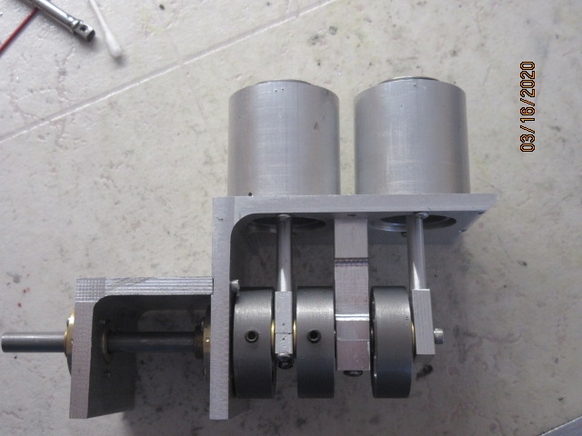
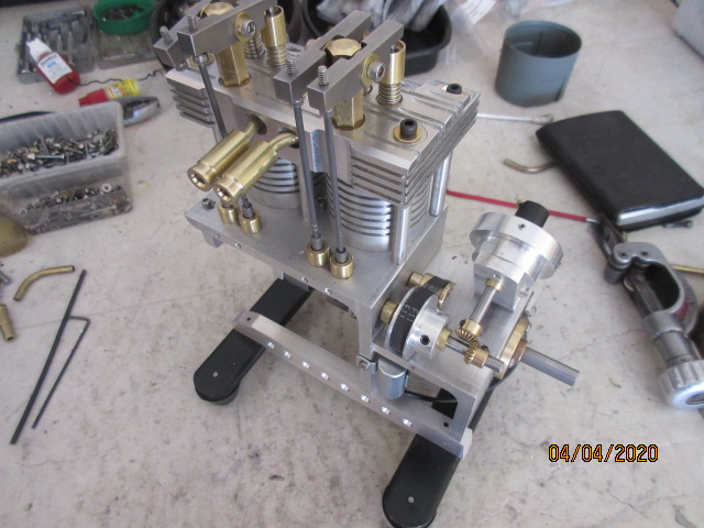
The best way was to pull back from the 2 inch crank to camshaft centerline. Lower and to the right, under where I want the lifters to be.
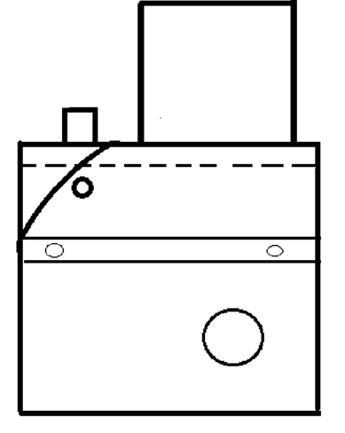
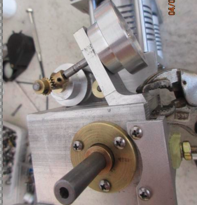
Belt slot will end before running off the deck and if too much slack in the belt, can reorder. Most likely a MXL78 tooth.
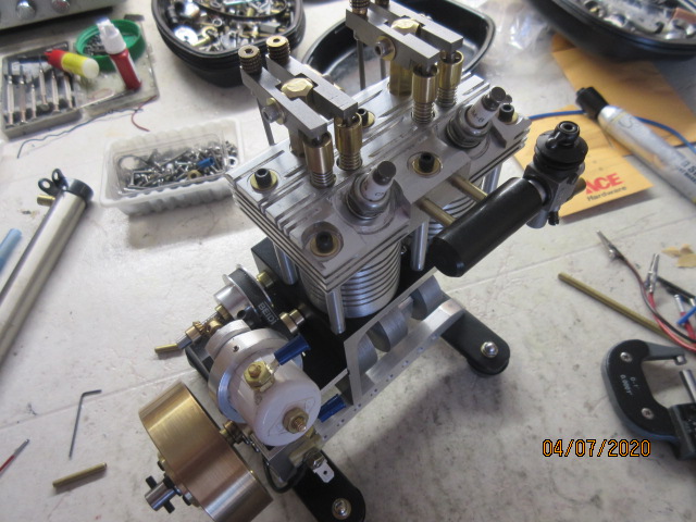
Trying an idler to take up the slack now and it will work fine with the 81T belt. Locate with a couple of transfer punches and drill the frame.
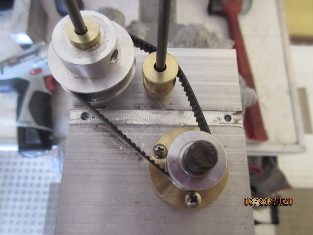
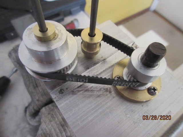
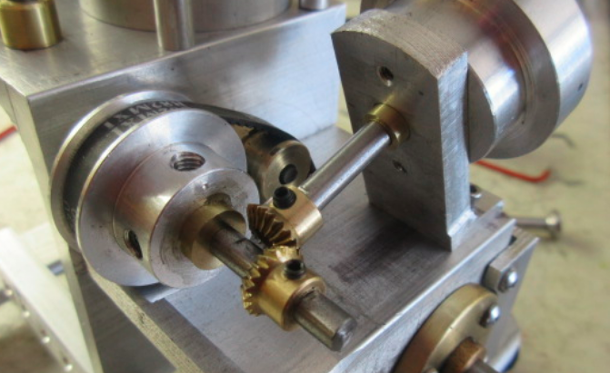
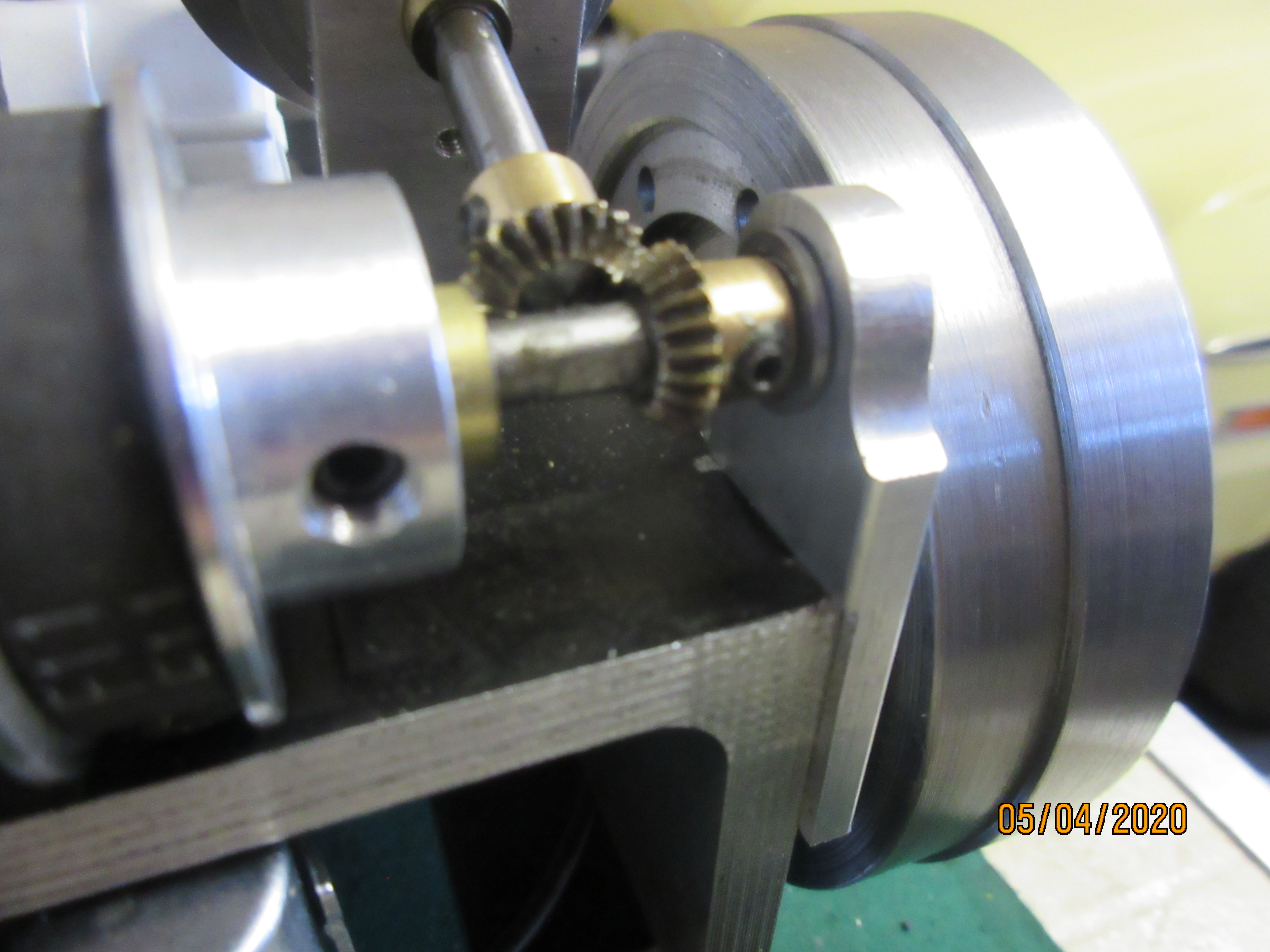
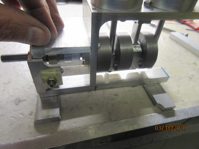
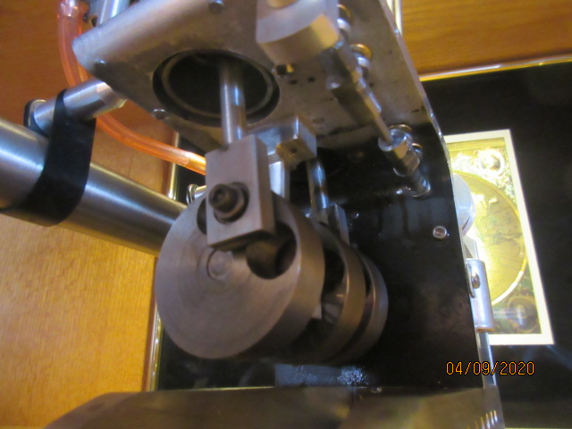
One caveat with the choosen location of cam sprocket is its flange sits right on top of the short deck now. With a slitting saw, I milled a shallow trough in front of the sprocket to the end of the deck for the clearance. Trimming the flange back about .025 in. would have done the same..... but I was looking for adventure with the slitting saw!
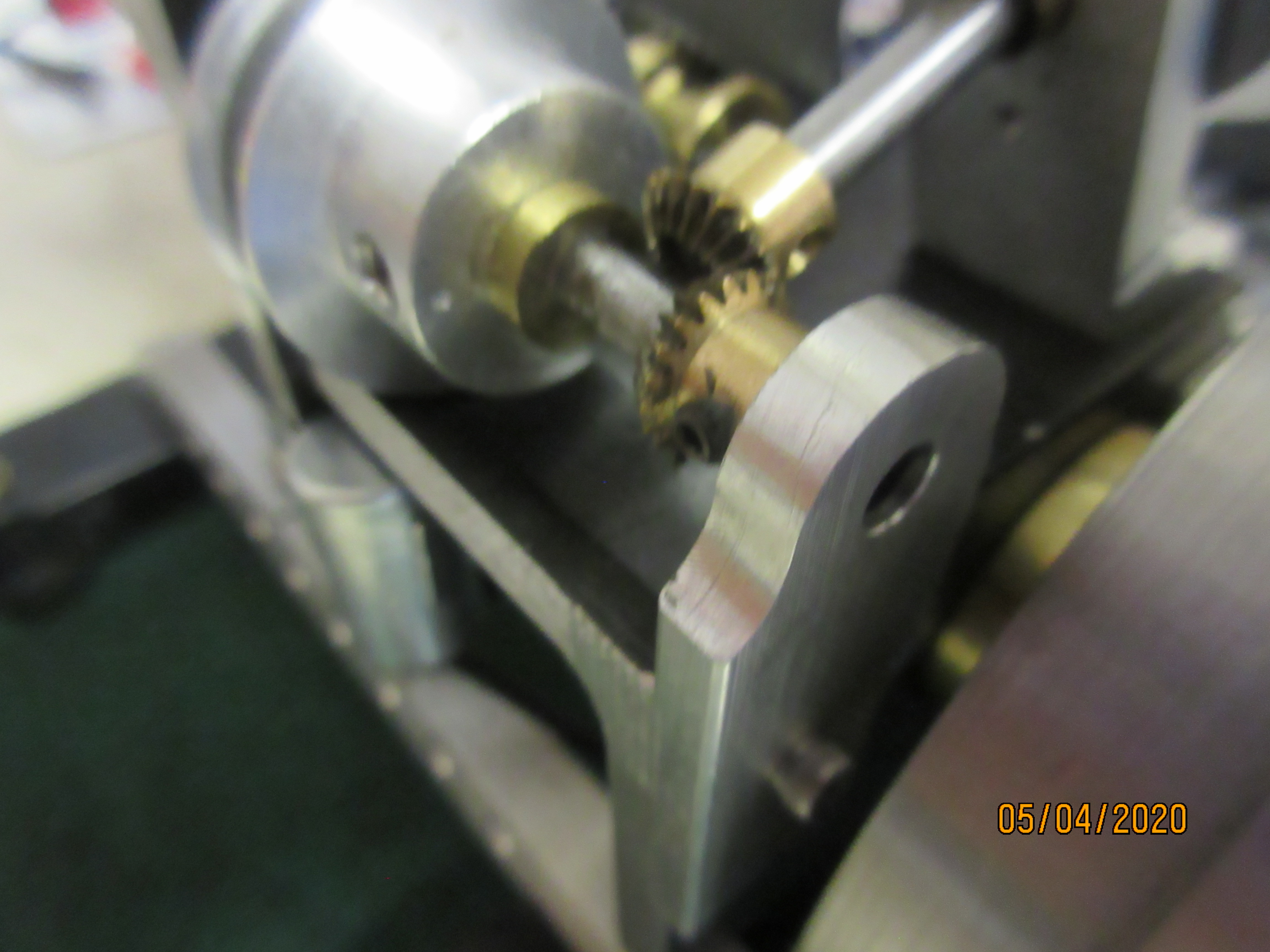
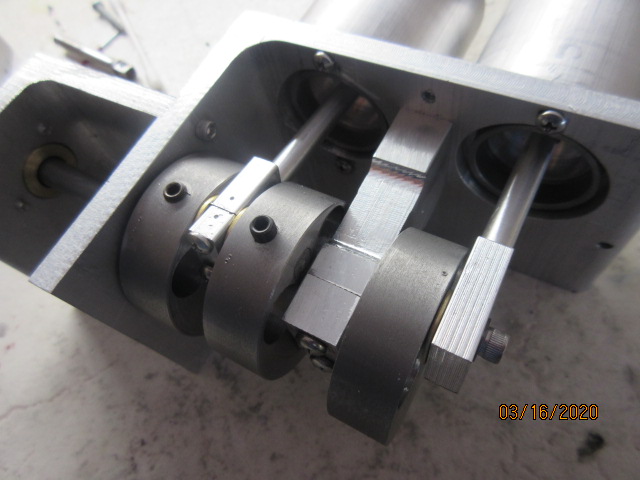
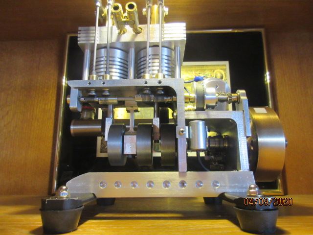
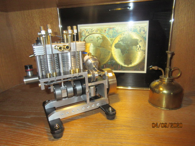
Still going to be tight under the lifters. So I re-bush the sprocket for a 1/8 in. shaft now. These cam lobes start form 5/16 in. 12L14 round stock secured with 4-40 set screws to their shaft.
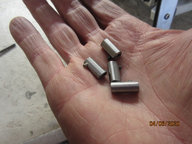
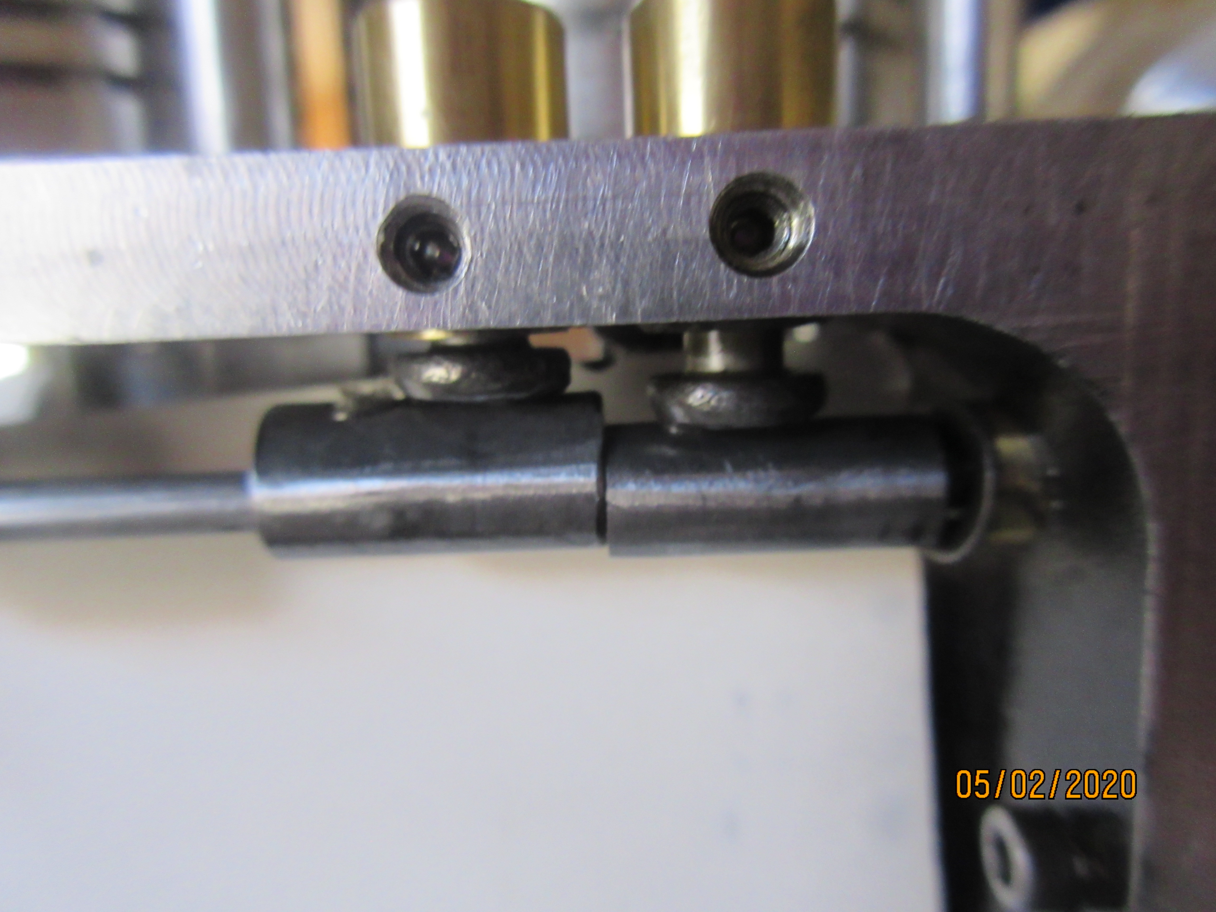
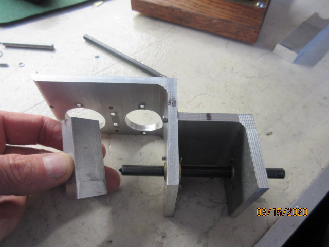
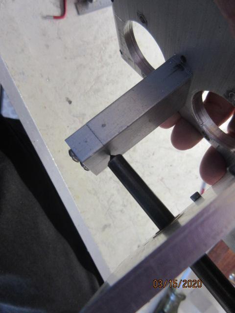
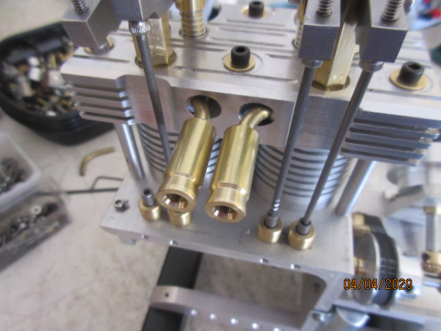
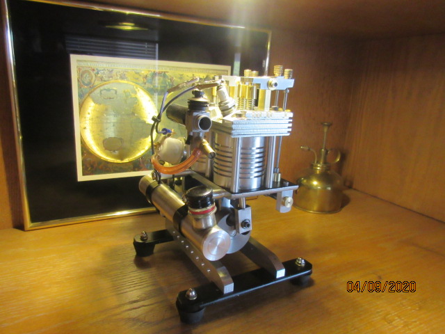
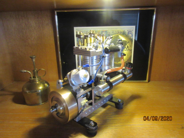
Back on the other side, I shorten the lifter guides to be flush with the cylinder deck underside and cut back the lifter heads so they have some space between the lobes and guides. Of course....I just made it!

Belt slot will end before running off the deck and if too much slack in the belt, can reorder. Most likely a MXL78 tooth.
Trying an idler to take up the slack now and it will work fine with the 81T belt. Locate with a couple of transfer punches and drill the frame.


One caveat with the choosen location of cam sprocket is its flange sits right on top of the short deck now. With a slitting saw, I milled a shallow trough in front of the sprocket to the end of the deck for the clearance. Trimming the flange back about .025 in. would have done the same..... but I was looking for adventure with the slitting saw!
Still going to be tight under the lifters. So I re-bush the sprocket for a 1/8 in. shaft now. These cam lobes start form 5/16 in. 12L14 round stock secured with 4-40 set screws to their shaft.

Back on the other side, I shorten the lifter guides to be flush with the cylinder deck underside and cut back the lifter heads so they have some space between the lobes and guides. Of course....I just made it!



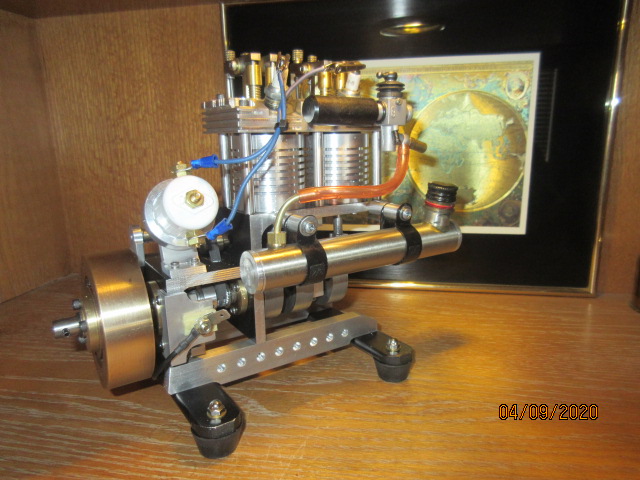
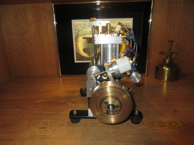
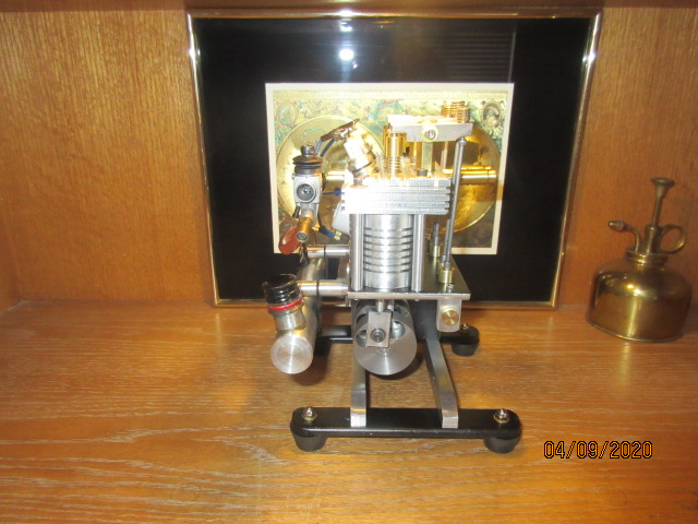


![MeshMagic 3D Free 3D Modeling Software [Download]](https://m.media-amazon.com/images/I/B1U+p8ewjGS._SL500_.png)


![DreamPlan Home Design and Landscaping Software Free for Windows [PC Download]](https://m.media-amazon.com/images/I/51kvZH2dVLL._SL500_.jpg)


![TurboCAD 2020 Designer [PC Download]](https://m.media-amazon.com/images/I/51UKfAHH1LL._SL500_.jpg)


