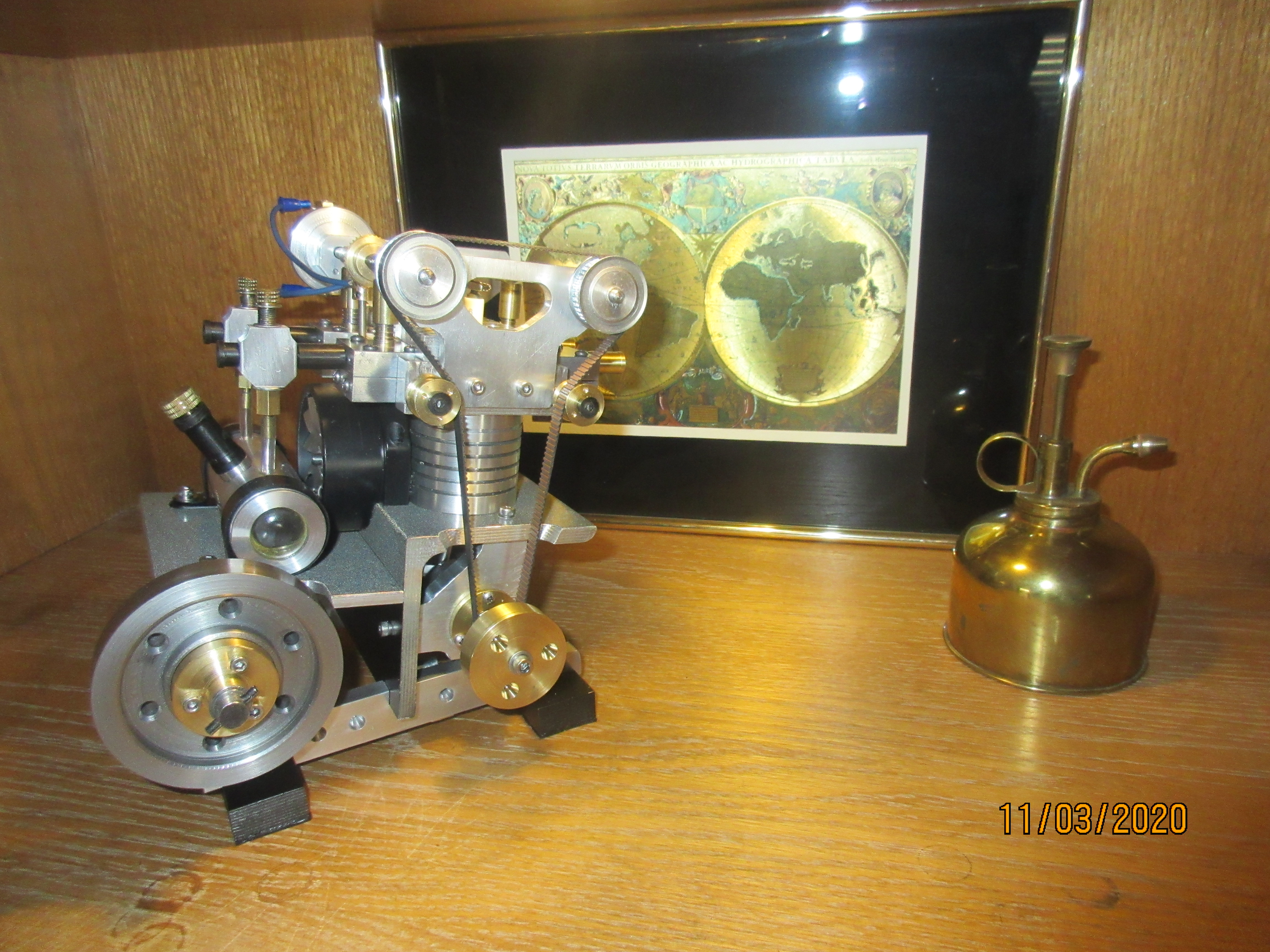
LONGBOY'S "WEDGE RUNNER" Model Gas Engine.

Home Model Engine Machinist Forum

Help Support Home Model Engine Machinist Forum:

This site may earn a commission from merchant affiliate links, including eBay, Amazon, and others.
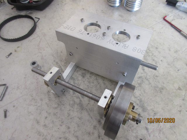
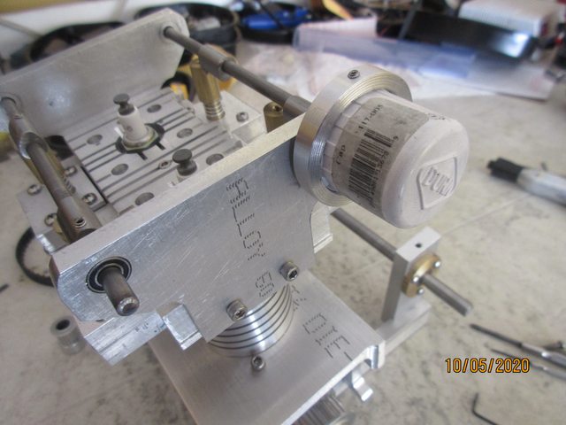
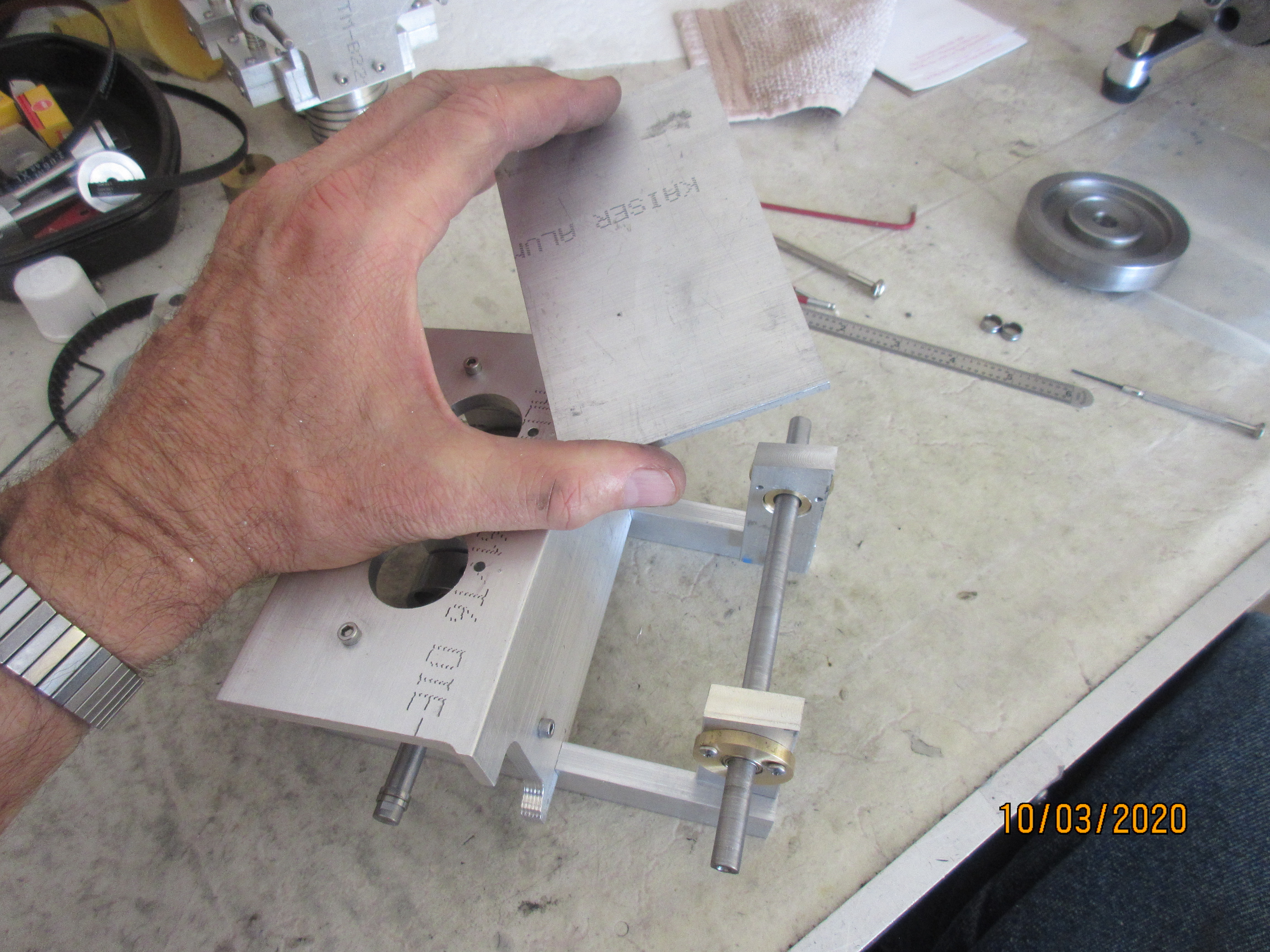
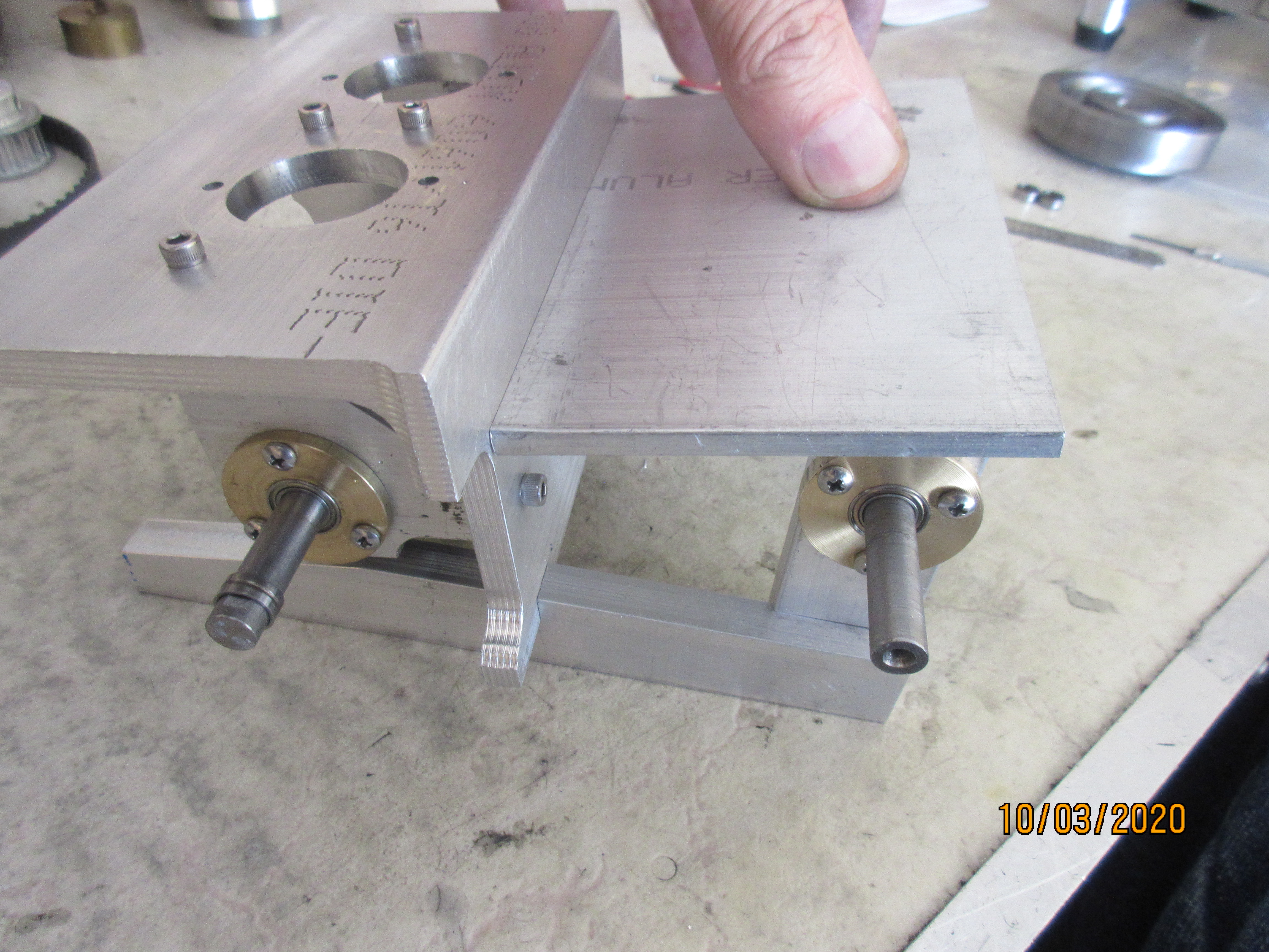
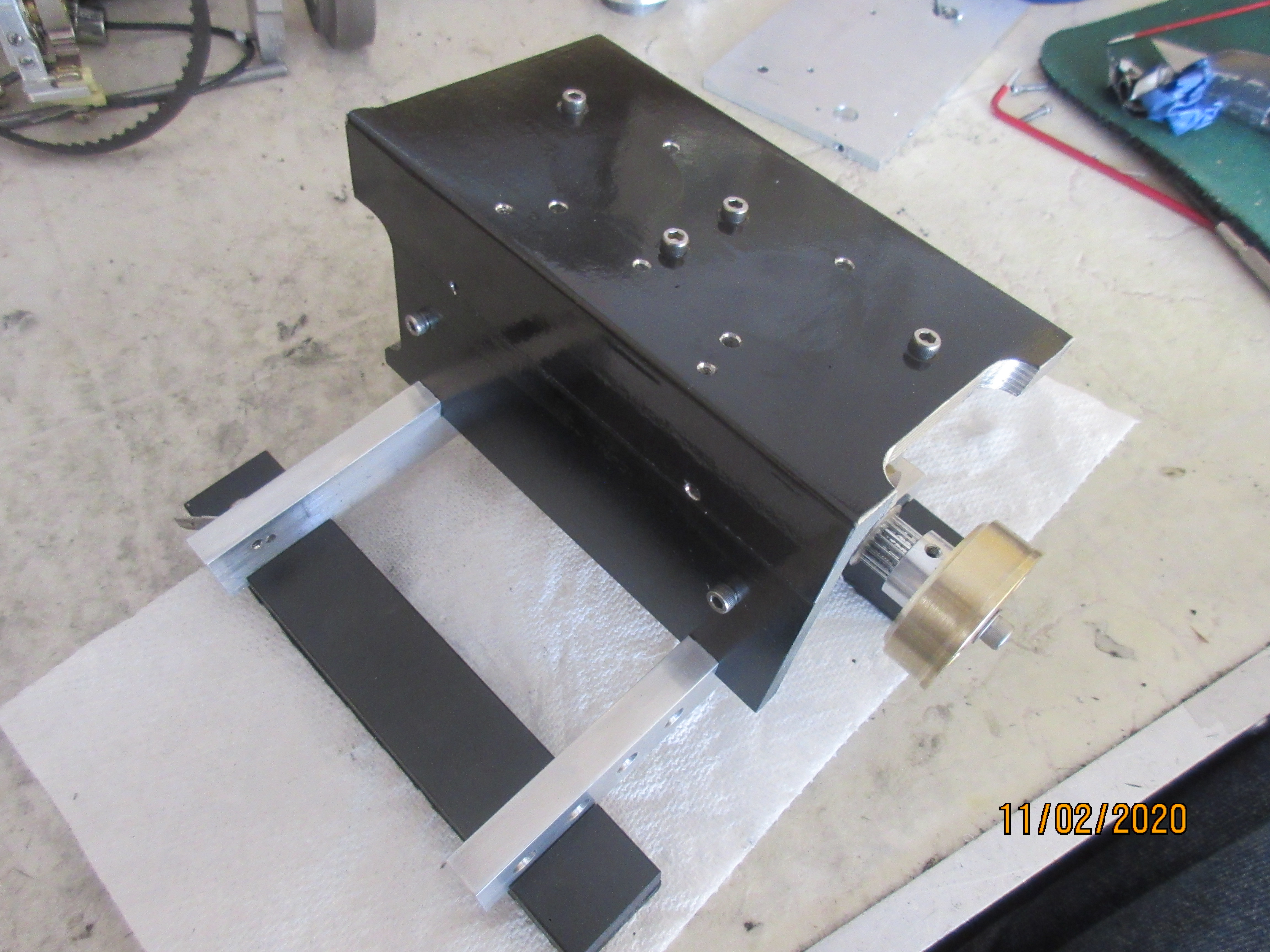
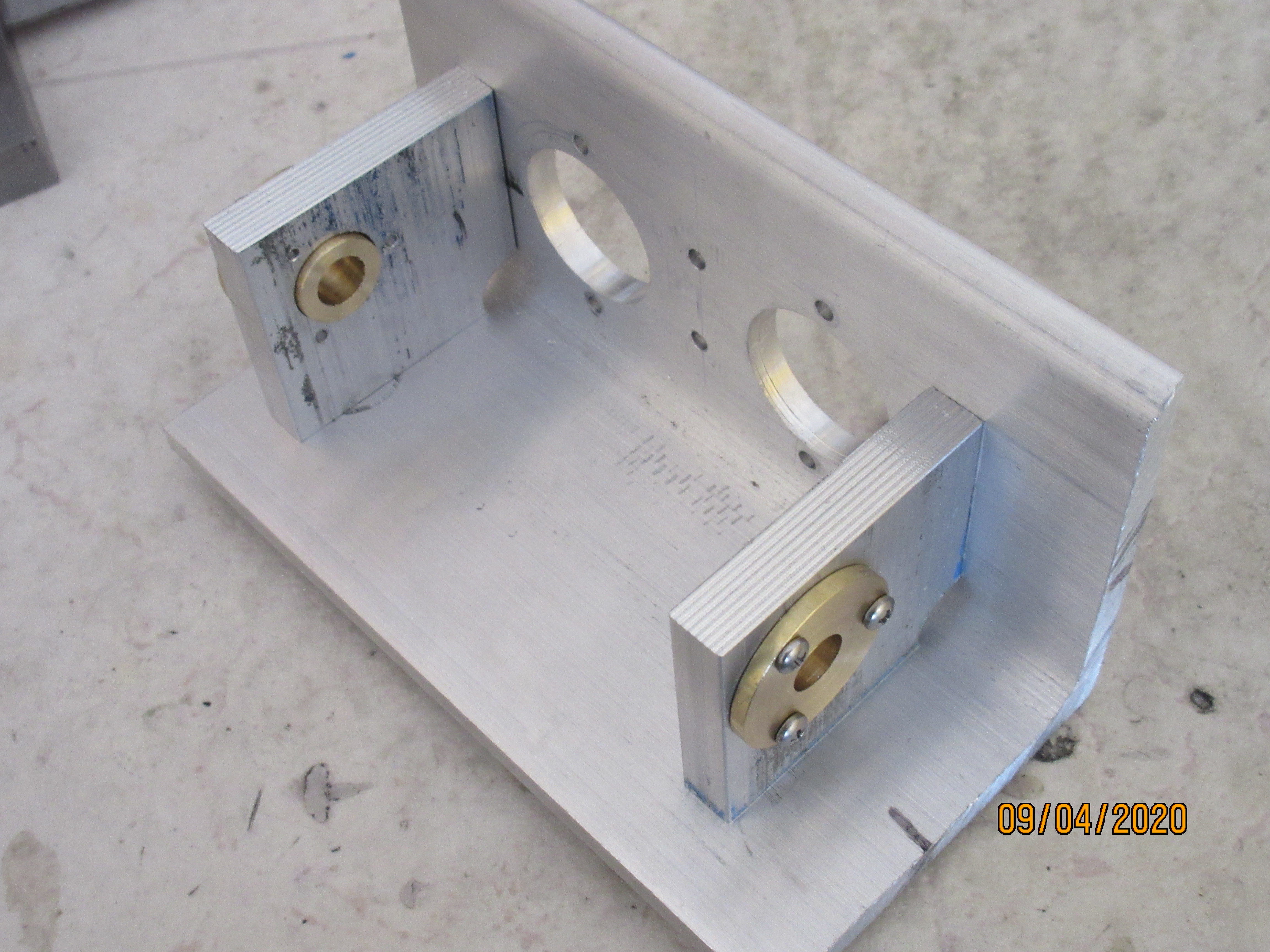
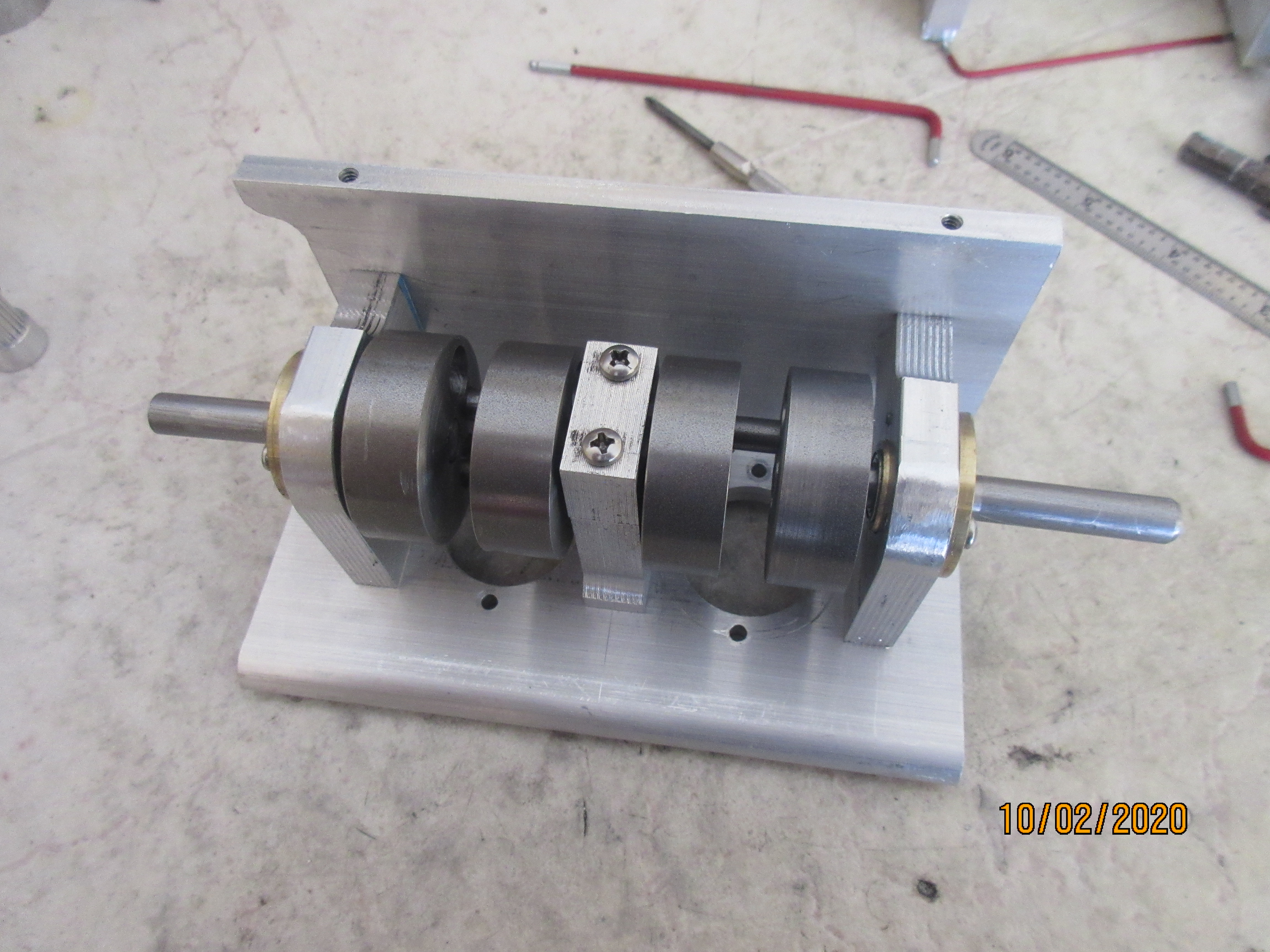
Under the deck, the crankshaft rolls along between the bearing carriers bracketed by 3/8 in. aluminum stock fastened to both the vertical and horizontal legs of the angle frame piece.
sMkIhNT.jpg


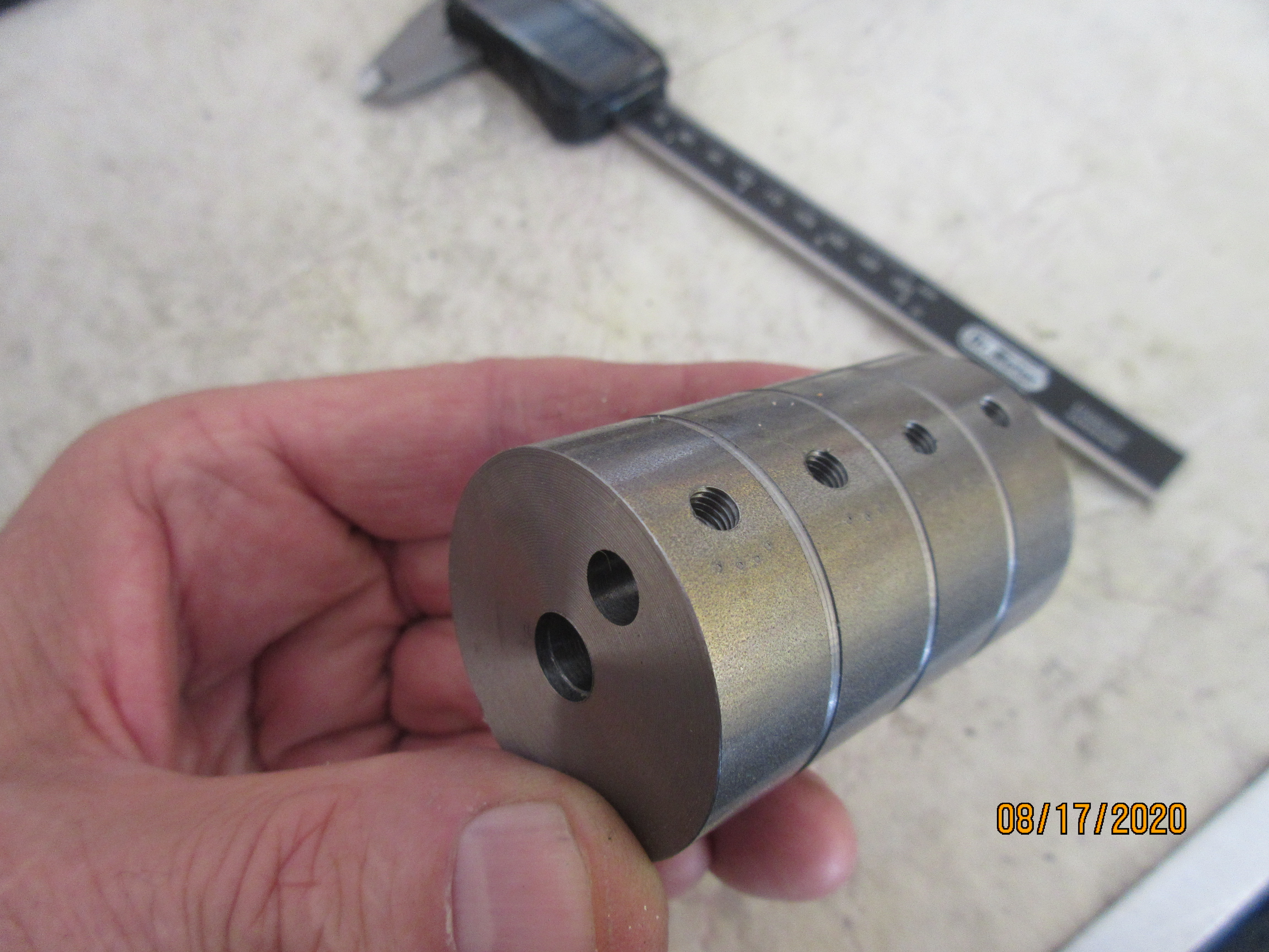
A log of crank webs to be parted off to cage the con rods. These are 1.5 inch diameter with the throw for a .75 in. stroke.
vlXLMma.jpg


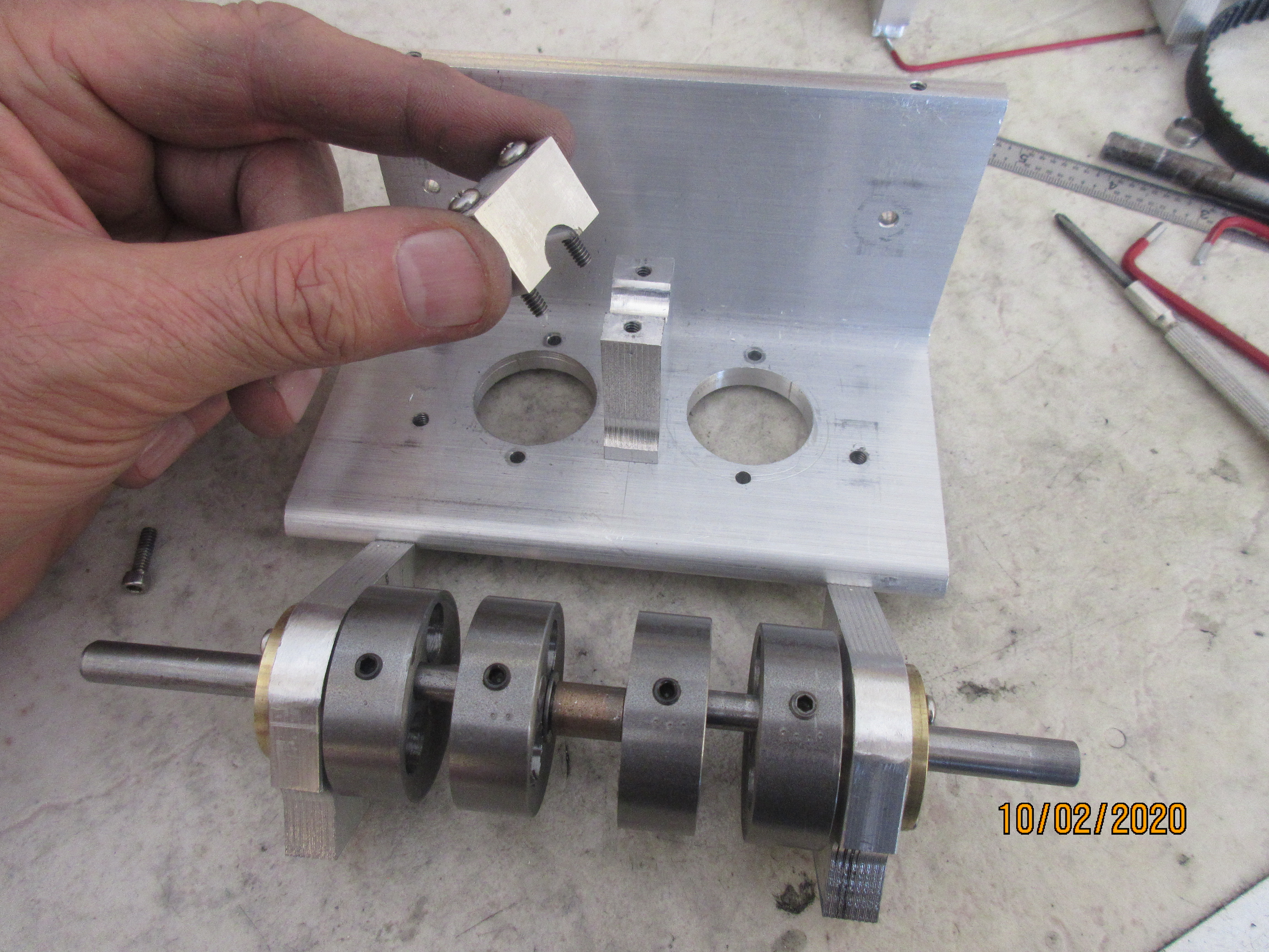
A center bearing of an Oilite bushing for the crankshaft supported by a 1/2 in. wide aluminum tower. R1810ZZ rollers for the brass bearing carriers.
8b4PVvc.jpg


For WEDGE RUNNER, smaller diameter crank webs allow the crankshaft to be placed closer to the top deck plate for a shorter lower end of the engine. The trade off here is that the piston/ rod assembly no longer can be removed or loaded from the bottom of the cylinders as the piston skirt no longer clears the webs.
MjEG0Ud.jpg


Back to the two screw over a three screw hold down of the cylinders upon the deck, you can see their access between the webs to pull the top of the engine off by disconnecting the cam drive belt. Yes, the crank can be removed to pull the piston/rod too by pulling a drive off of each crank end..... just builder's choice ease here!

MjEG0Ud.jpg
 
Last edited:
Valve blocks made from .250 in. flat stock, 1 x 1.25 in.
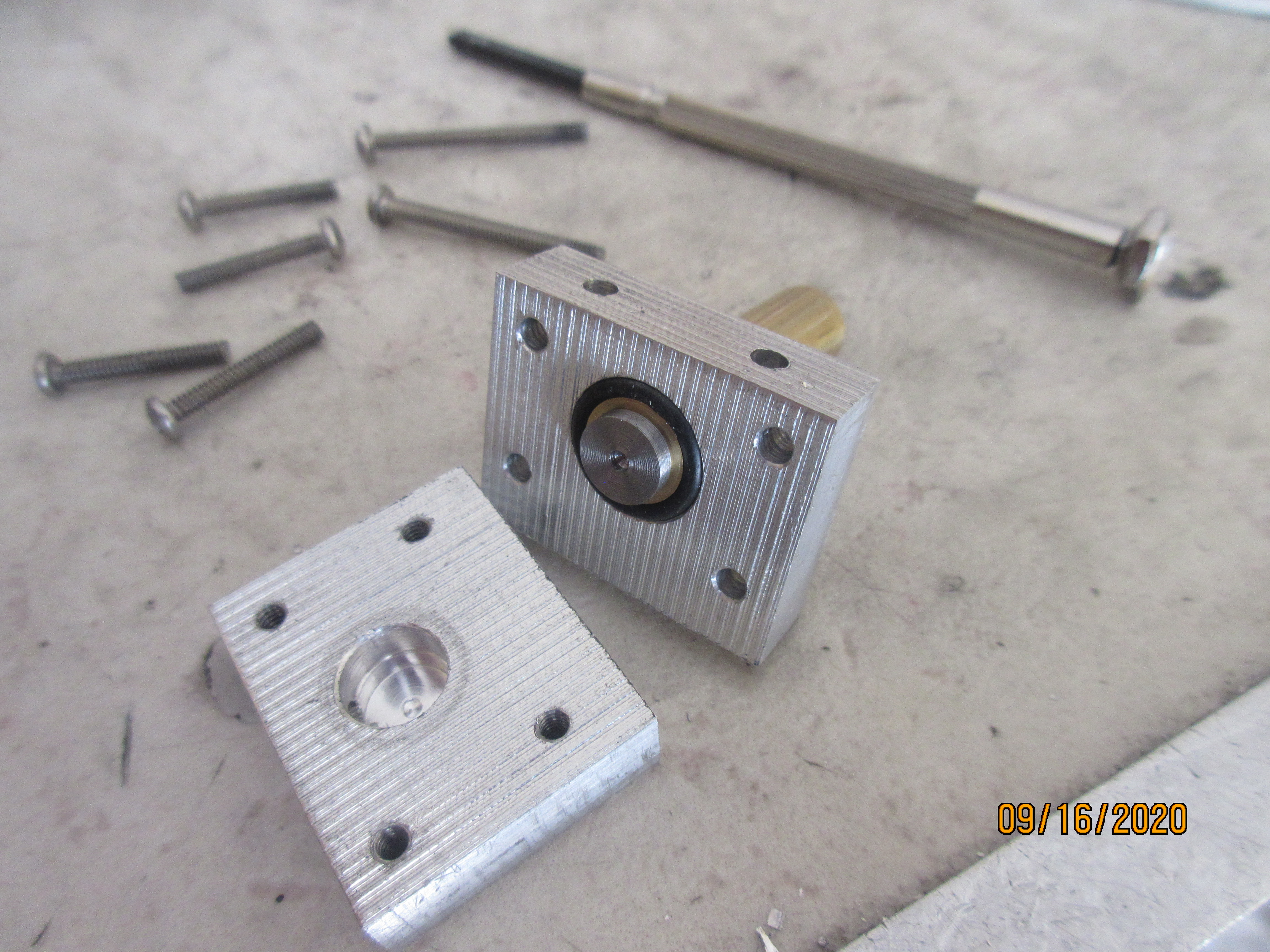
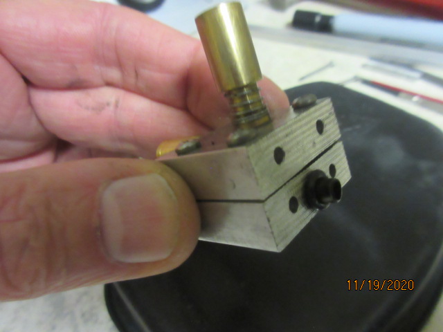
An O-ring seals the valve between the two blocks. Mounted to the head, a brass tube with o-ring seals the valve port to cyl. head port.

w90y34P.jpg

Can you say a little more about your valve design, or is it in another thread? Its a reciprocating piston valve (brass?) with spring return. But where is the seal/seat between in and out ports? Presumably, as brass on alu wears, you'll get increased leakage between valve and body. Is that significant, would you remake the body block after. while? thanks!
 
Can you say a little more about your valve design, or is it in another thread? Its a reciprocating piston valve (brass?) with spring return. But where is the seal/seat between in and out ports? Presumably, as brass on alu wears, you'll get increased leakage between valve and body. Is that significant, would you remake the body block after. while? thanks!
Thanks Anatol. Let's split one open for a look/see. This is a steel valve in a brass guide in the top block side mated to the lower half side with the port to head. The o-ring over the valve guide seals the two block pieces. The valve on it's seat of the valve guide is the seal between the in/out ports of each block assembly. In this photo you can't see the ports drilled in each block by their position on my table which I believe leads to your question.
w90y34P.jpg

You see here the brass tube from the lower half in port matches the head port and and is sealed with the o-ring slipped over tube covering the compression/ ignition cycle. Valve guide with spring and bucket retainer totally ordinary too.
2aJgMbC.jpg

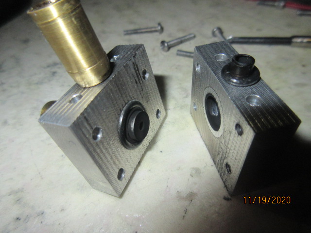
This is the ex. block for WEDGE RUNNER with stubby brass exhaust pipe. Shown here with both ports up side. When bolted together one is rotated 180 for the correct orientation mounted to engine.
2fOAUbB.jpg


These valve blocks have proven pretty versatile. Easily removed for service. They can be rotated 180deg. depending if your cam is above or below. You can make the valve blocks as long as a candy bar for multi cylinder inline engines. They are excellent for atmospheric intakes. Remote install to cylinder head for a flat head low profile design and with just one port into cylinder head combustion chamber, a 3 block sandwich with both in/ex valves can be arranged! -----Dave.
 
Last edited:
Hi Dave
thanks for quick reply. Taking the first pic 90/16/20, I see one port (to head) in the side of the cavity in the lower block at at about 9oclock. Where is the other port? Diametrically opposite in the same block?. Or is it in the upper block, ie the brass tube vertical in the left (top) block in pic 11/19/20? If so, don't you run out of bushing for the valve to run in? Or am I missing something?
thanks!
 
Hi Dave
..................... Or is it in the upper block, ie the brass tube vertical in the left (top) block in pic 11/19/20? If so, don't you run out of bushing for the valve to run in? Or am I missing something?
thanks!
Yes, in that last photo you see both block halves ...with the port side up. You are looking at the exhaust pipe on the left block where the valve guide would be horizontal looking at the head of the valve.
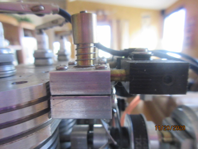
Here is a view installed on another engine. Top half to intake manifold. Bottom half into cylinder head. -----Dave

A727HMH.jpg
 
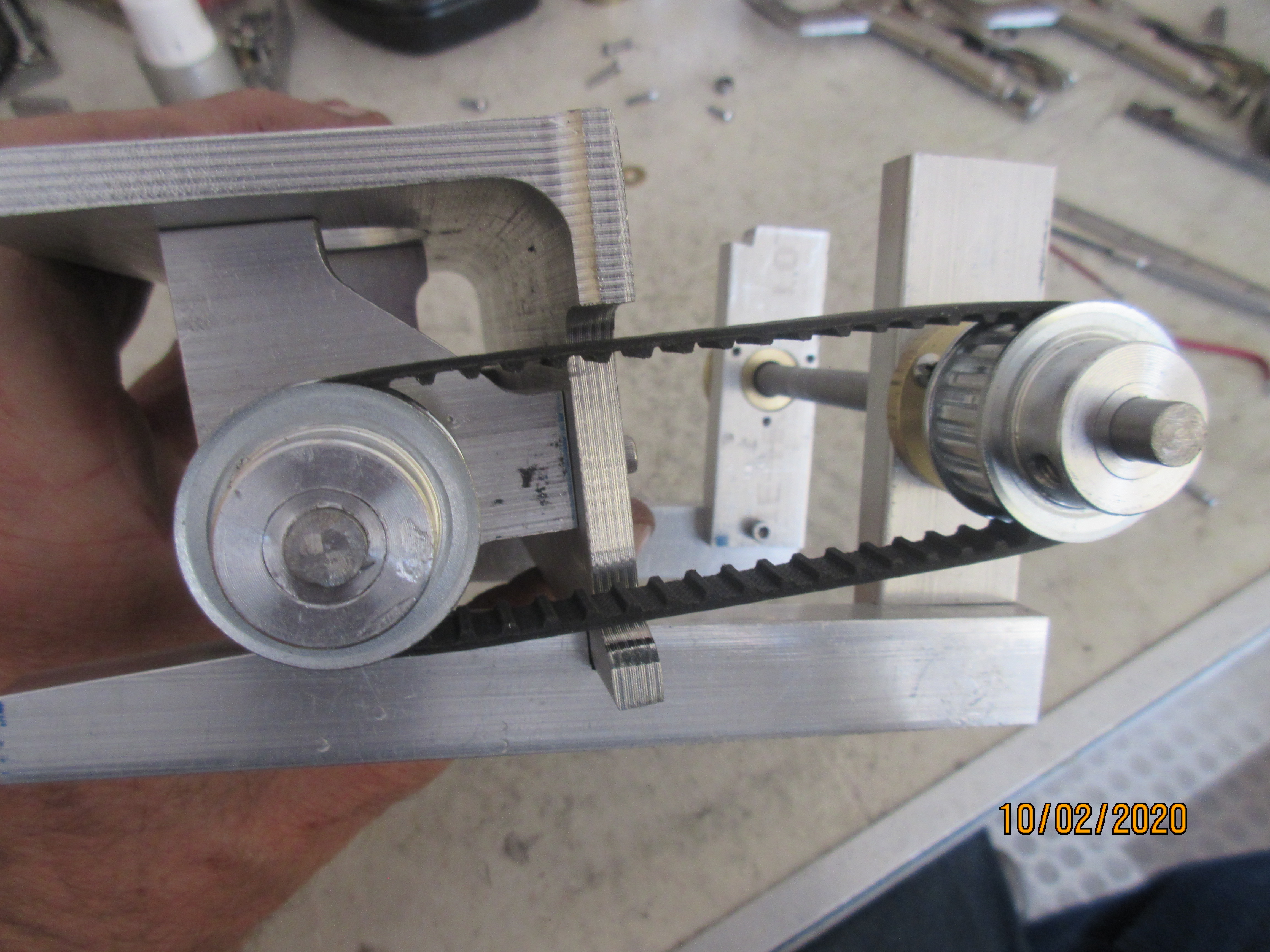
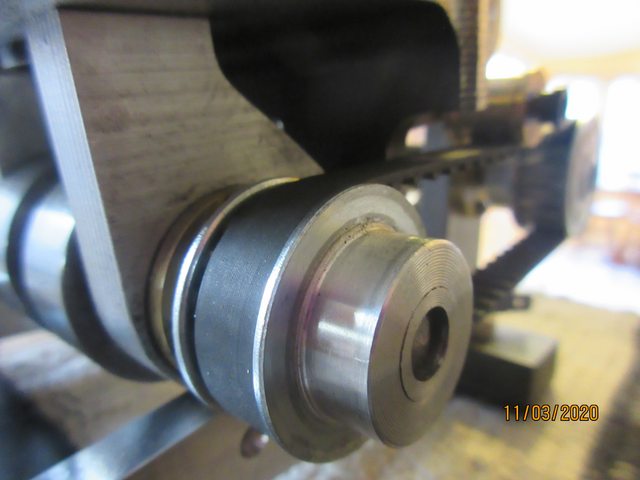
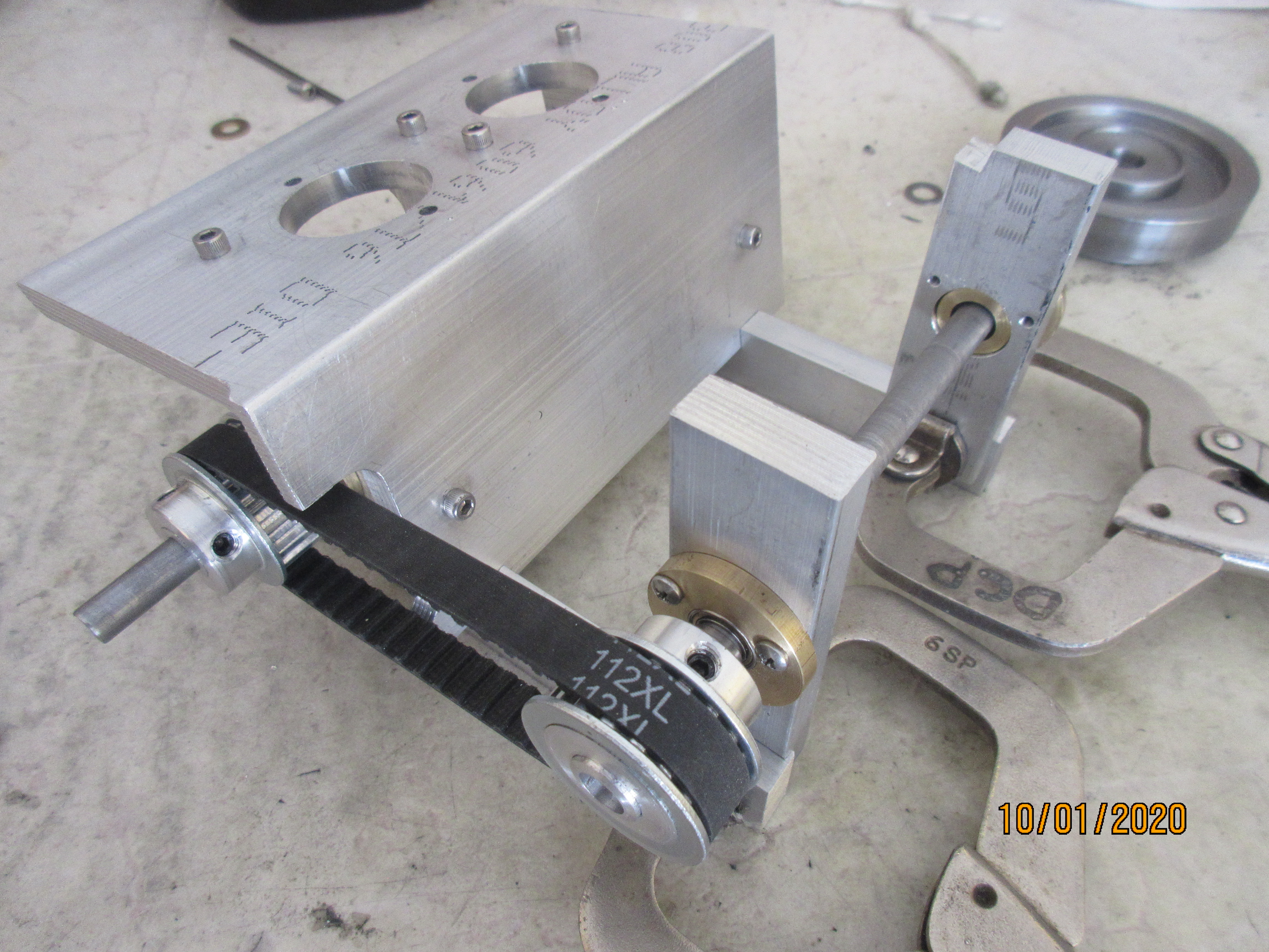
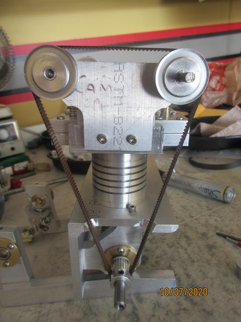
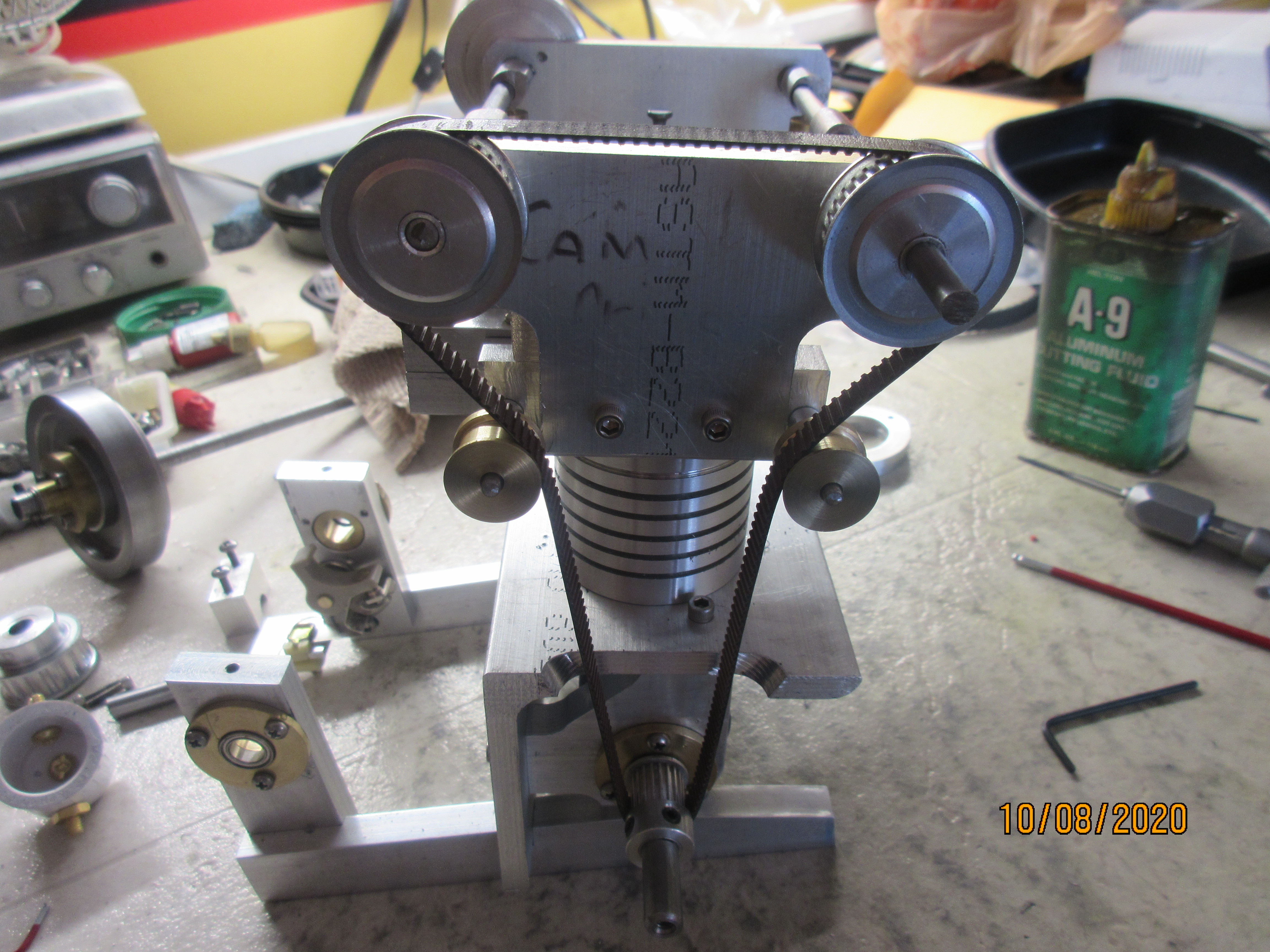
The drive from the crankshaft to the flywheel is done by a pair of XL 18T sprockets. Wanted a more substantial belt here than using the MXL sized belt and sprockets.

zEAolmN.jpg

Ya that looks pretty meaty!
q1csWdrl.jpg


At the backside of engine another pair of towers for the bearing carriers and the shaft for ign. points cam and flywheel.

3oqB4LN.jpg


Flywheel is a 3 inch steel diameter unit.

2SAndSIl.jpg
 
Last edited:
thanks Dave

Top half to intake manifold. Bottom half into cylinder head. -----Dave

My first question is why? Why are the 'in' and 'out' ports not both in the lower block?
My second question is - when the valve is all the way up, isn't almost all the out of the valve guide?
Or am I (still) missing something?
Thx!
 
Yes, keep study on the photos. One port has to go thru the valve guide and the other has to be on the down side of the valve head so when valve opened you have flow between the ports. That is possible but not practical using a single piece block for both ports. Your issue then becomes how do you remove the valve from the guide then for service when you glue in the guide? Installing the retainer and spring may be difficult then. The valve lift is around .100 inch lift. The valve stem area of the guide is about .650 in. Don't see how you find the valve out of its guide. -----Dave
 
Last edited:
This is my 1st. twin cam engine. 20/40T MXL sprockets and belt. I order the belt running some thread over the sprockets with cyl. head torqued down and idlers in place, measure its length. In the photo, I have a spacer under the radiators to raise the camshafts to take up the slack, testing out the appearance.

JiJAz4xl.jpg


Looks like three stories of stair steps to get from the crank to the cams! I go back to the original plan with the idlers and pull the spacers. I have a place on the cyl. head to mount their axles, and I like moving, rotating objects on my engines!

TqlhNND.jpg


Over on the other side of the camshafts, a convenient place for the distributor.

Ylqg72Hl.jpg
 
The rear deck plate is some thinner 3/16 in. material. Looking at both maintaining the inclined rake of the cylinder deck or a parallel mounting with the table surface.
nCkqR9q.jpg

I go with the cyl. deck match.
txny38K.jpg

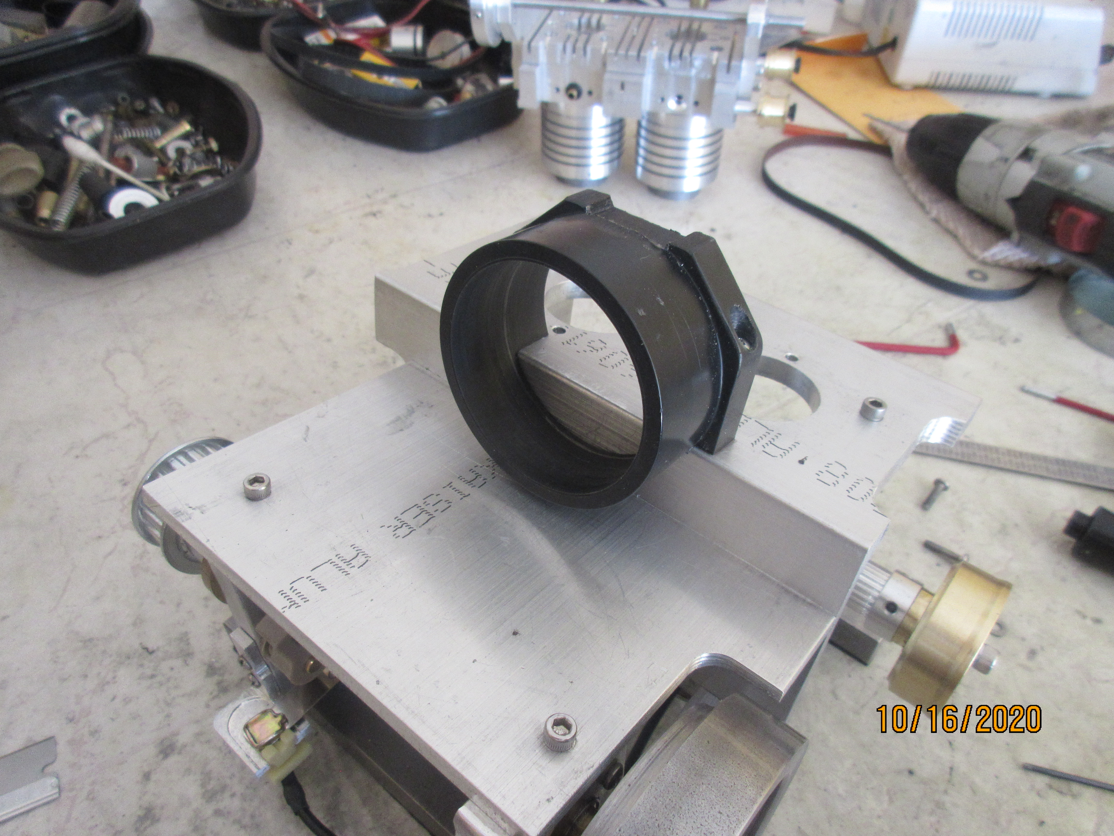
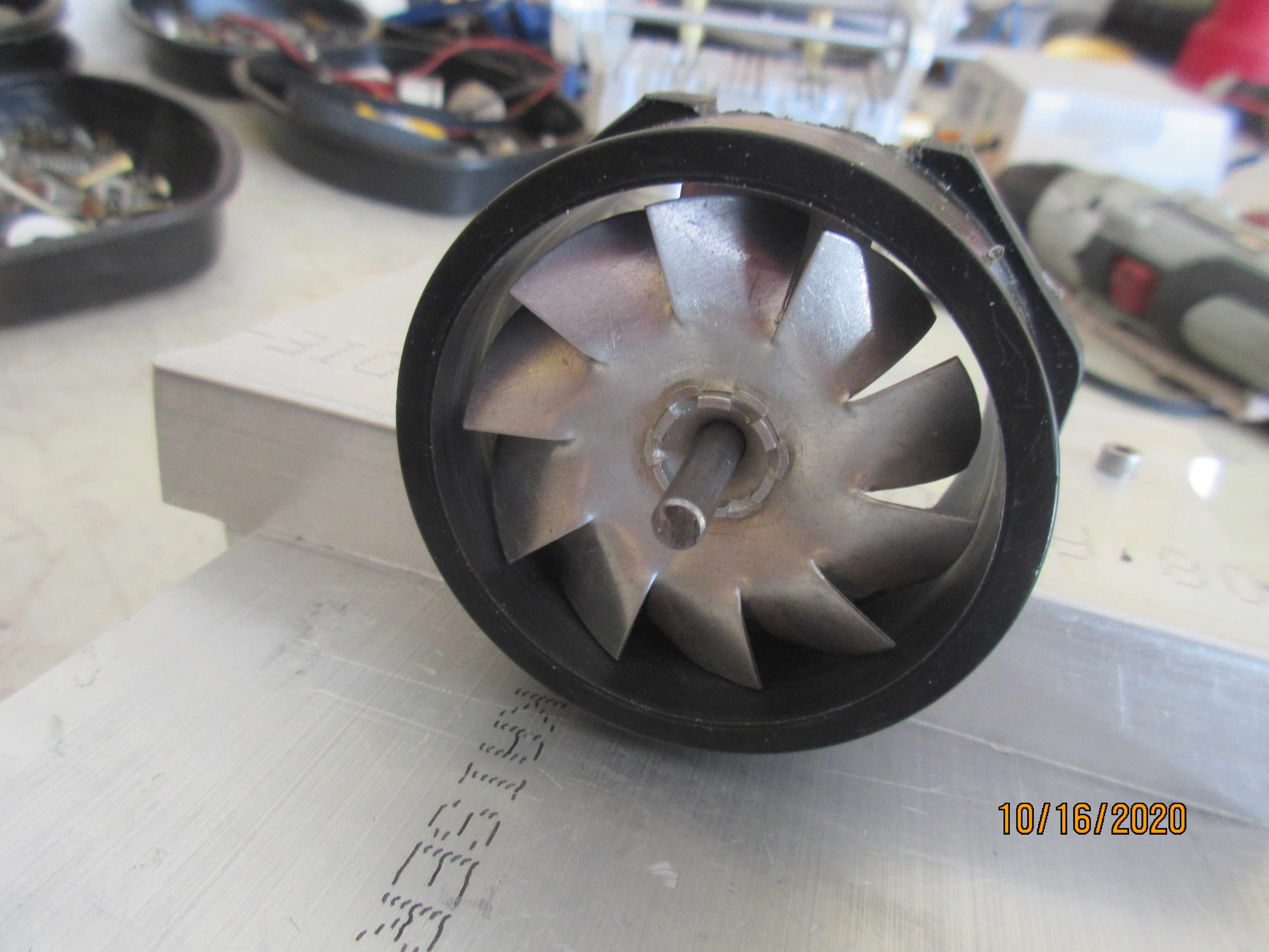
Looking to put a cooling fan on WEDGE RUNNER. I start with a bulkhead connector cut and trimmed to the shape I need.
ApdrcuB.jpg

Looks like I'll have about 2/3rds. of the fan exposed to airflow across the radiators.
hno3k5U.jpg
 
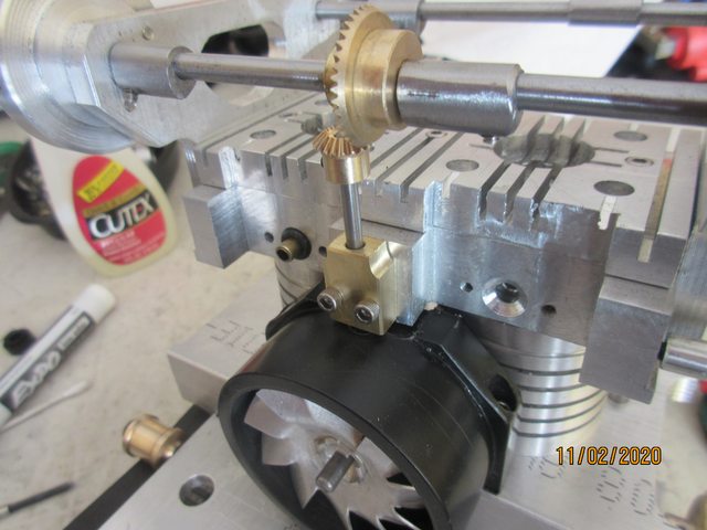
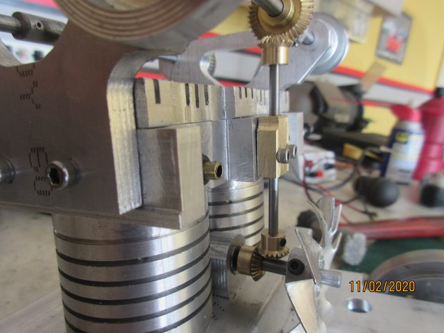
With no parallel shafts to belt drive the fan, a right angle drive of gears brings in some power.
askRIVKl.jpg

With the camshafts overhanging the edge of the cylinder head plus a space between the valve blocks, it is a straight intersect with the fan shaft. A brass bushing mounted for the vertical shaft and four umbrella gears make up the drive.
6soFb5Ml.jpg

With the gear ratios available, the fan turns at about .8 :1 of crank speed.
 
Last edited:
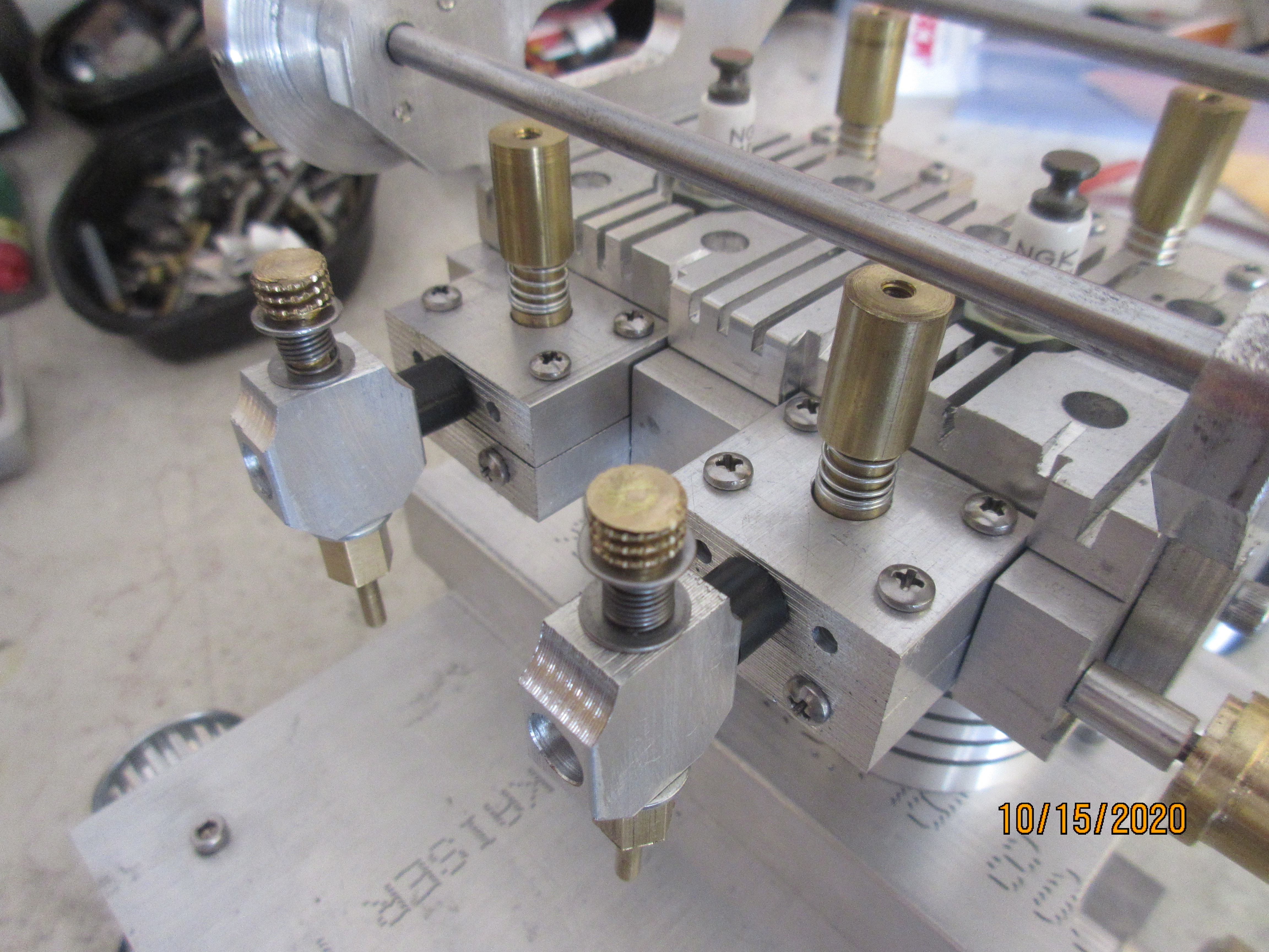
A pair of carburetors thread into the valve blocks with a short tube of Delrin. More of a fuel mixer with a fixed bore, they do not throttle and a narrow rpm range is set by needle position and ign. timing advance.

2mvKZ3n.jpg

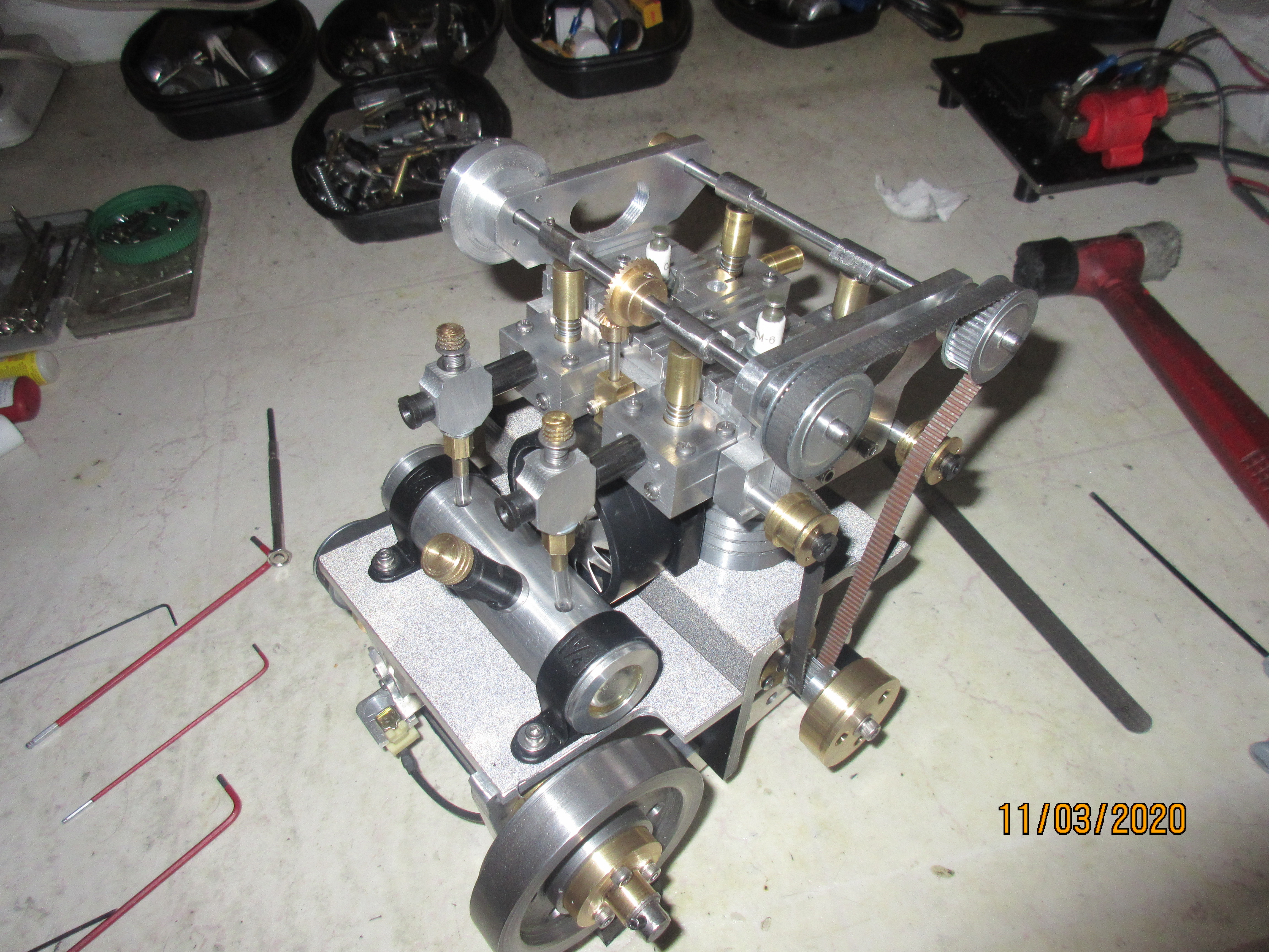
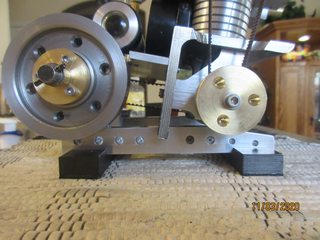
The horizontal deck plates get a film of 3M Scotchbrite reflective vinyl. Makes for some interesting flash photos. To the frame rails a couple bars of 1 x 1/2 in. steel for the base cross bolted to lower the center of gravity. A strip of roofing rubber is epoxied to their bottoms for a no slip grip to the table surface.

4qvaBHc.jpg

p91FcwW.jpg


And another project completed from LONGBOY ENGINE.
2DgsSzEm.jpg

Premiering soon!
 
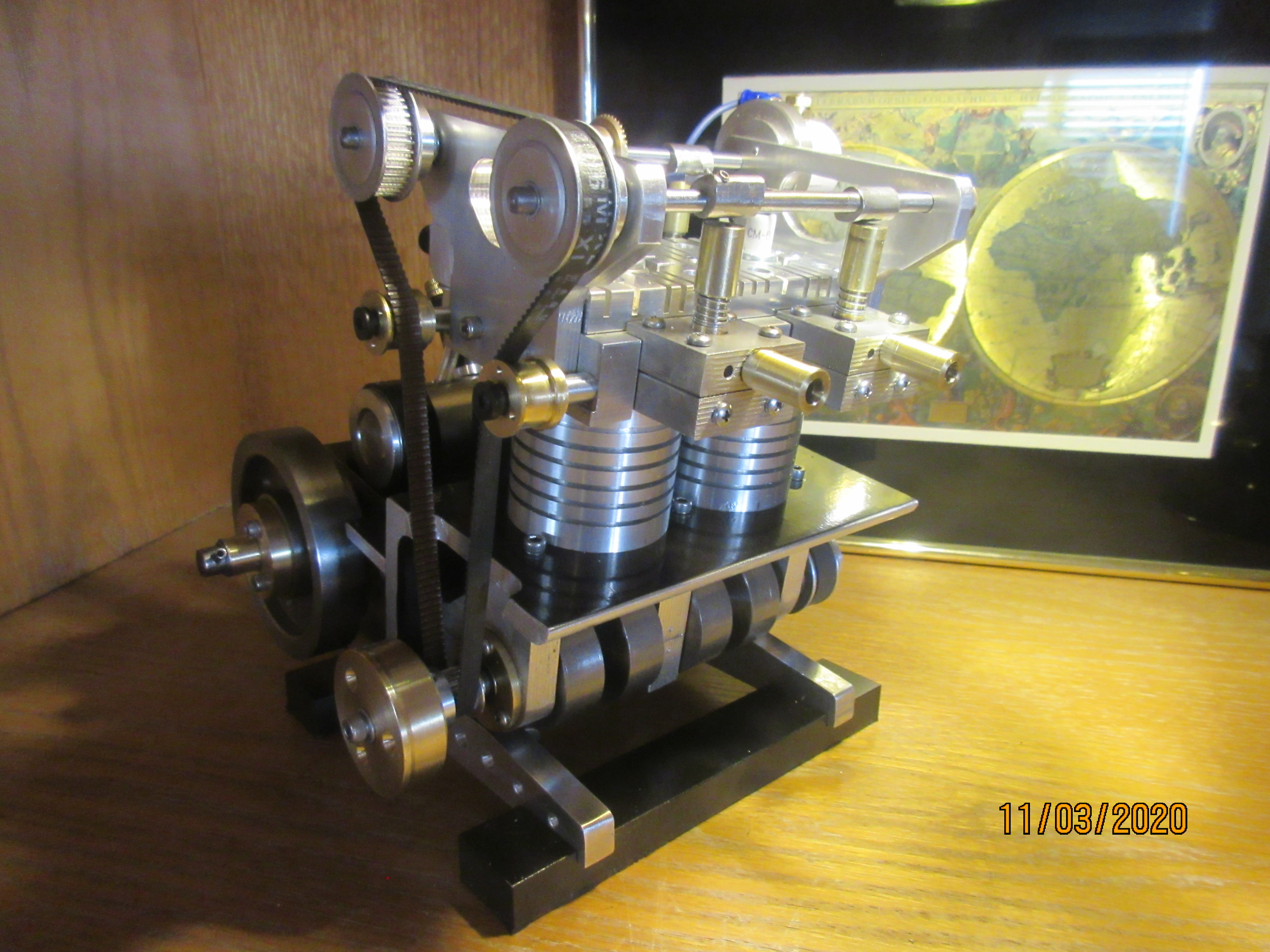
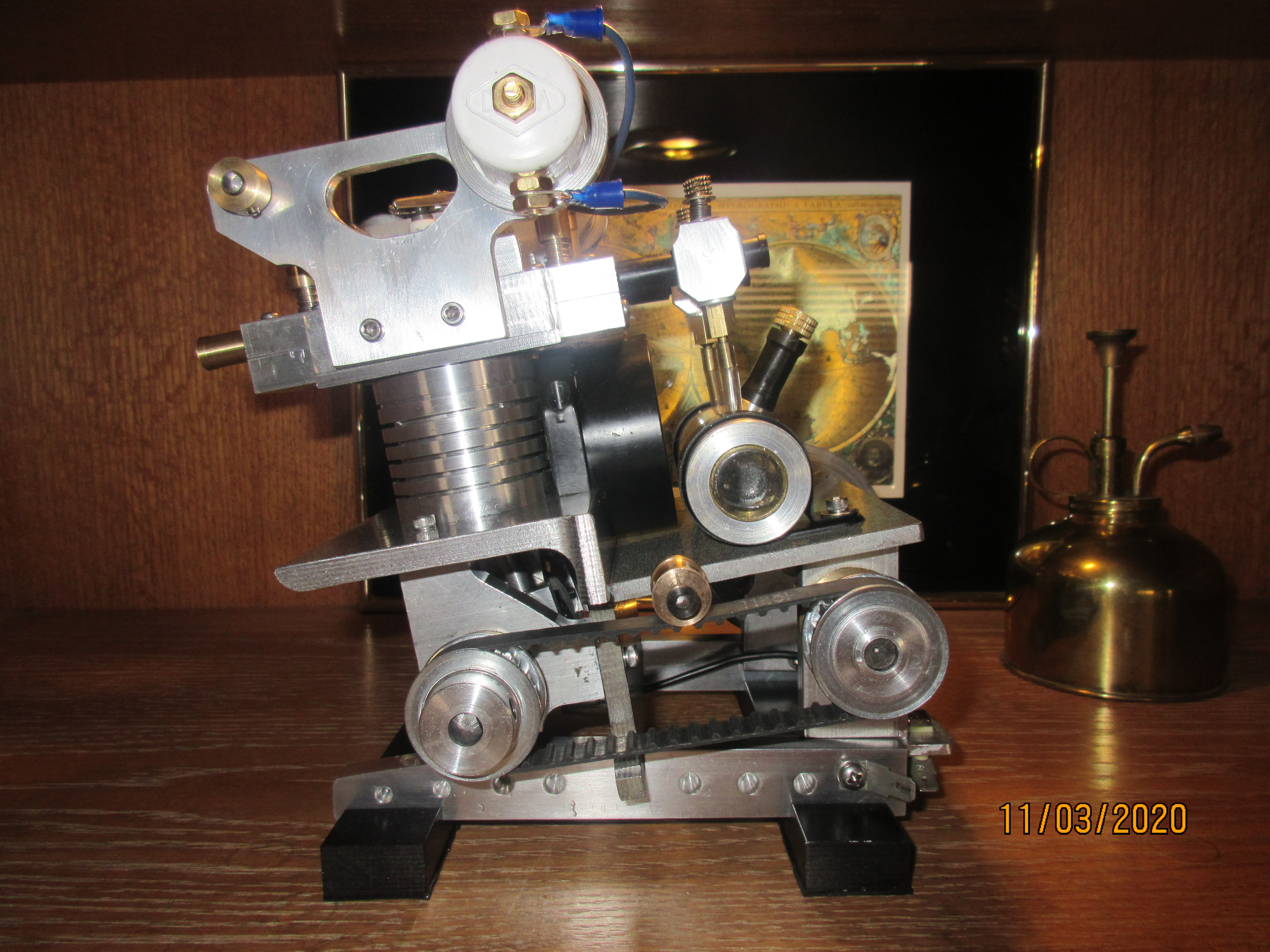
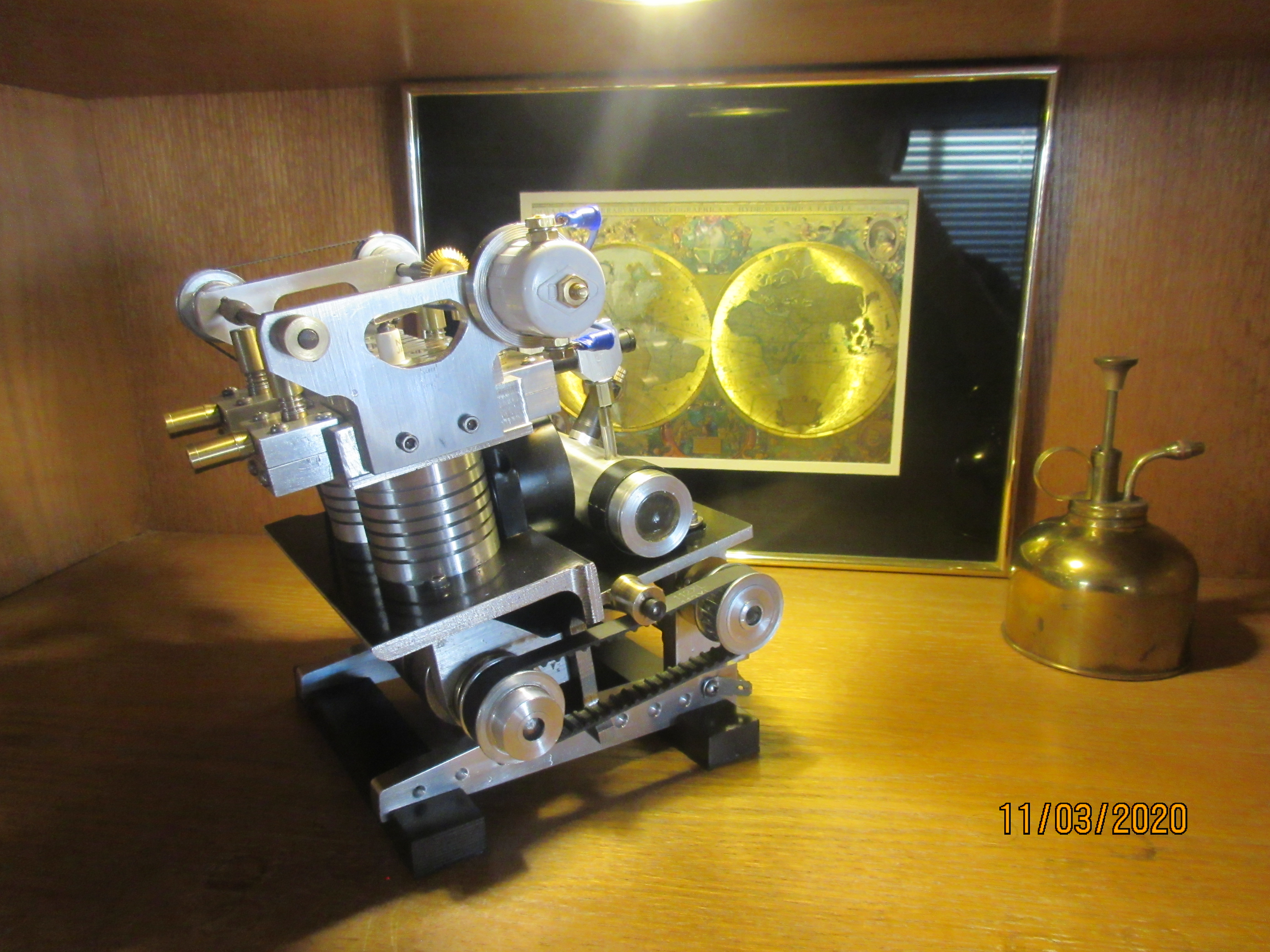
A 20cc two cylinder model engine, WEDGE RUNNER is built on a canted forward frame base. Twin camshafts, dual carbs, belt driven rear shaft flywheel plus it's cylinder angle find a way to express a hint of a parallel twin motorcycle engine as well by profile viewpoint the stance of a classic street rod.......... ( or is it a lawn tractor) !
xAfz5NC.jpg


WEDGE RUNNER was started in middle August and finished early November.
3gK3sUC.jpg


9G6Dxzx.jpg


tjJHPHS.jpg


And a little video! Enjoy and thanks for keeping with my adventures on the forum! ----- Dave.

 
Congratulations on another wonderfully designed engine
I’m impressed with the speed that you build these beautiful machines
 
A 20cc two cylinder model engine, WEDGE RUNNER is built on a canted forward frame base. Twin camshafts, dual carbs, belt driven rear shaft flywheel plus it's cylinder angle find a way to express a hint of a parallel twin motorcycle engine as well by profile viewpoint the stance of a classic street rod.......... ( or is it a lawn tractor) !
xAfz5NC.jpg


WEDGE RUNNER was started in middle August and finished early November.
3gK3sUC.jpg


9G6Dxzx.jpg


tjJHPHS.jpg


And a little video! Enjoy and thanks for keeping with my adventures on the forum! ----- Dave.


It must be good--it got a smile out of me.
 
Job well done Longboy. Like your design and it runs just as good.
Cheers
Willy
 
Back
Top