Line-Shaft Clutch

Home Model Engine Machinist Forum

Help Support Home Model Engine Machinist Forum:

This site may earn a commission from merchant affiliate links, including eBay, Amazon, and others.

Brian Rupnow

Design Engineer
Project of the Month Winner
Joined
May 23, 2008
Messages
15,212
Reaction score
8,515
Location
Barrie, Ontario, Canada
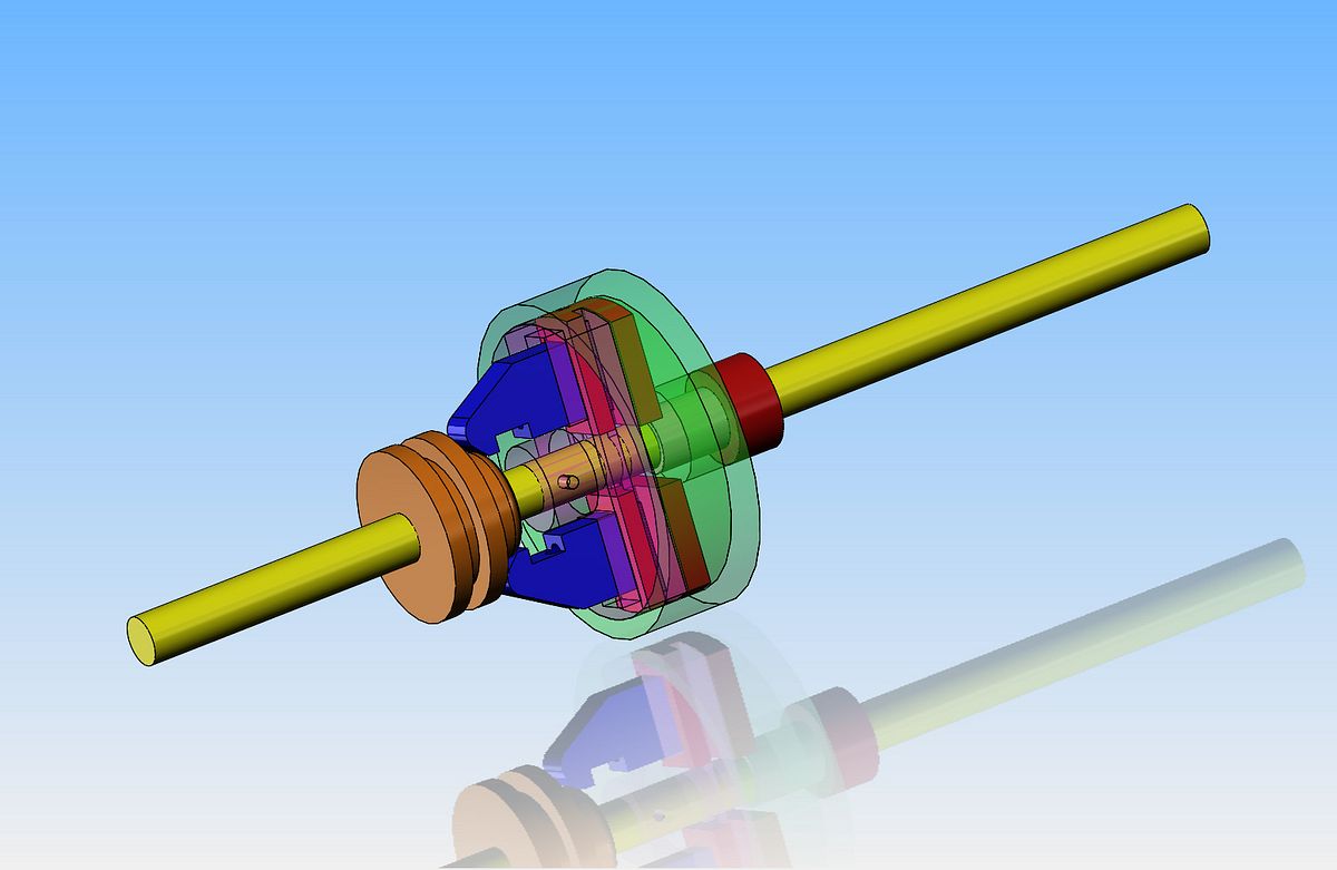
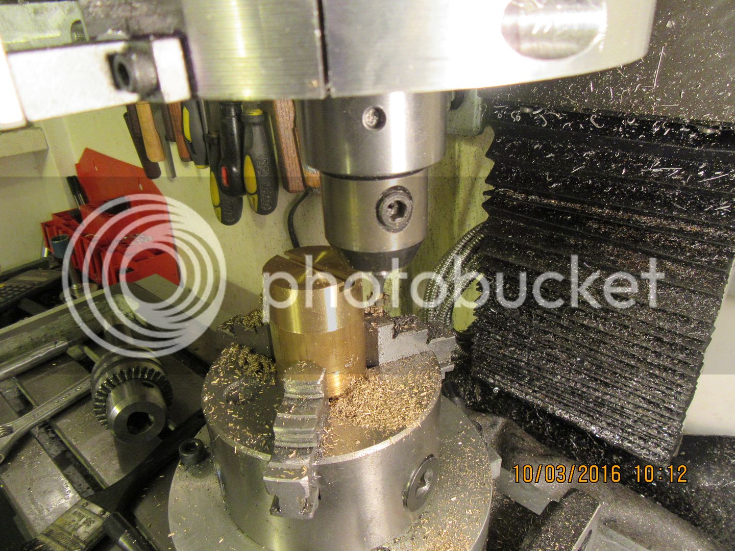
After doing a bit of research on line shaft style clutches, with a manually operated swing lever to actuate them, I've decided to build one, "Just to see if I can!!" (This train of thought was brought about by John who is building the 19th century machine shop diorama on Model Engine Maker). A bit of research yesterday showed me that the smallest I can possibly make this clutch is 1.75" outer diameter, to work on a 1/4" diameter shaft. There are a few parts to this "expanding shoe" style of clutch that become too small for me to make if I try to make the clutch smaller in diameter. I have made use of a keyslot cutter in a very unorthodox manner to get started on this, and since I'm doing this in "real time" I will keep you posted of my progress.---Brian

 
Hello Brian
Nice work .
Could you please describe briefly how T slots are cut?
It is mystery for me.
Thank you.
 
Hello Brian
Nice work .
Could you please describe briefly how T slots are cut?
It is mystery for me.
Thank you.
Look at the top picture. It shows exactly what I done. First I cut a slot .125" wide full depth across the top of the brass part in the chuck with an endmill. Then I chucked up the keyway cutter and ran it all the way thru the brass part. Done!! I am sure that this is probably not the correct way to do it, but it is what I done.--Brian
 
Some very close (fiddly) work here. First picture shows cutting a 1/16" slot into one side of the sliding pressure shoe. Second picture shows the sliding pressure shoe profiled for a sliding fit into the brass part. That slitting saw blade is 1/16" wide!! Next step will be to separate the sliding shoe into two pieces, one to bit on each side of the center of the brass.

 
Interesting project Brian. I shall be following with great interest. Looks too fiddly for me to attempt tho :D
 
Herbie---It IS fiddly. it is just about at my limit for "small stuff". The "sliding pressure shoes" are finished. the side where you can see the heads of the socket head capscrews faces inward towards the clutch drum. The side where you see the slots and the shanks of the #40 shcs faces out. The dark blue "actuator arms" (as per the solid model) fit thru the slots in the brass part and bolt to the "sliding pressure shoes". There is a full 8 hours in what you see here.

 
This is a "real" line-shaft clutch set-up, and it is what serves as the basis for my design. One thing that the "real" one has and my model doesn't (because of scale/space restrictions) is individual adjustments for the tapered surfaces on the arms that the sliding cone interacts with. That would serve to adjust the sliding pressure pads on each side to contact the inside of the drum equally. At the scale I am working, there simply isn't room for threaded adjusters, so I will have to resort to grinding the angled contact surfaces on the dark blue "arms" to get equal travel/pressure on both pressure pads.
 
I don't THINK that there were any springs in there to retract the shoes and disengage the clutch, but I really don't know. That picture is one I downloaded off the internet. I have never seen one of these clutches in "real life". If anyone has info to the contrary, please let me know.---Brian
 
I'm going to make a small change to the pulley drum. Since most of the machinery I drive use 1/8" diameter rubber O-rings as drive belts, and we will want to actually "field test" this clutch, I have put a groove in the green drum to keep the o-ring in place on the pulley.
 
This morning I decided to make "easy" parts, that just required turning. I checked all of my bins, and found that I didn't have any round steel large enough in diameter to make the outer 'drum'.---I did however have a piece of 2" diameter cast grey iron left over from the cylinder on the Rupnow Vertical engine. I decided to use it. This has a good side to it, in that it won't need a bushing where it rides on the revolving line-shaft when the line-shaft is turning and the pulley is not turning. The bad side is that cast iron isn't the strongest metal going, so I left the rim a bit thicker than my original intent. the finished diameter is now 1.725". I did find a piece of cold rolled steel to make the set collar from. That set collar keeps the drum from "drifting away" from the correct position.

 
Brian, I think you may have a problem with getting much force where the shoes press on the pulley. The actuating arms look to be about three times as long
as the shoe guides. After the shoe makes contact with the pulley, any further pressure on the actuating arms will create a torque that tends to jam the shoe in its guide slot, losing a lot of the actuating force to friction. You could improve things by making the arm as short as possible.

However, It seems to me more likely that in the original device the arms are in fact levers, pivoted on the hub 'behind' the shoes. This would hugely improve the mechanical advantage obtained, and greatly reduce the chance of problems with friction within the mechanism.

HTH.
 
Well, it sorta/kinda works. The angle on the contact surfaces which I arbitrarily picked as being 45 degrees is too steep. I have a 45 degree angle on the nose of that 3/4" diameter slider and with the lathe running at about 60 rpm I can hold the pulley drum from rotating with a finger. If I use my other hand to force that 3/4" diameter slider against the "arms", the shoes do expand and make the drum rotate. However, I am sure a shallower angle will make things work with a lot less effort.
 
Brian, I think you may have a problem with getting much force where the shoes press on the pulley. The actuating arms look to be about three times as long
as the shoe guides. After the shoe makes contact with the pulley, any further pressure on the actuating arms will create a torque that tends to jam the shoe in its guide slot, losing a lot of the actuating force to friction. You could improve things by making the arm as short as possible.

However, It seems to me more likely that in the original device the arms are in fact levers, pivoted on the hub 'behind' the shoes. This would hugely improve the mechanical advantage obtained, and greatly reduce the chance of problems with friction within the mechanism.

HTH.
Charles--I can't disagree with your physics---but---if there was a pivot anywhere in that old picture I posted, and you slid that slider in between the arms, that would retract the clutch shoes, not expand them.
 
I changed the angle on the end of that 3/4" slider to an included angle of 60 degrees instead of 90 degrees, and it made a tremendous difference. The clutch is working just as I hoped it would. You have to keep in mind that those sliding shoes only have to move about .015" to make the difference between engaged and disengaged. If they had to travel any real distance, then I'm sure they would "cock over" and bind badly. I can feel a video coming on---
 
This morning I took successive cuts from the outside diameter of the coned 3/4" piece until I had it down to a diameter that would just slide between the arms under slight pressure to open them wider and engage the sliding shoes with the clutch drum. This was not something that could really be calculated with any accuracy. It was purely "turn a little bit and then try it" engineering. With my model, the "ideal diameter" should have been 0.520" diameter. In actuality, it was exactly 0.500" diameter, which is pretty darned close, considering the build up of tolerances and the shape of the arms. I have provided two pictures, one showing the clutch in the "not engaged" position--The "Not engaged" position shows a gap of 0.100" between the nose of the sliding cone and the brass hub. The "engaged" position shows 0 gap between the nose of the sliding cone and the brass hub. And yes, that is a Canadian quarter laying in the foreground to give e sense of scale. Our quarter is the same size as an American quarter .

 
It doesn't always start with a pretty 3D cad model. Sometimes when I'm hashing out exactly what I'll do next, I resort to good old pencil sketches to determine the direction I will take. I will now go from this preliminary sketch to a 3D cad model where I can input all the math data to create accurate models and detail drawings from.
 
So, we end up looking like this. The panther pink pulley is driven by an o-ring drive belt from one of my engines, to turn the lineshaft. When the clutch is not engaged, the blue pulley drum just sets there and does not revolve. When the clutch is engaged, the pulley drum does turn, and will drive an o-ring belt that powers one of my "work, work, work mechanisms, probably the moving staircase.
 
Um, no ... not if the pivot point is further down inside the pulley than the shoe.
Charles--You're right. I really like that idea. It would work better. Now all we have to do is find somebody who has one of the originals, have them take it apart and get some digital photos, and post them here where we can see what's inside. I have seen these in operation when I was a kid, there was a water powered line shaft sawmill about a mile from where I grew up. Unfortunately, 60 years ago I wasn't interested enough to look inside one.---Brian
 

Latest posts

Back
Top