Lil' Henry Build

Home Model Engine Machinist Forum

Help Support Home Model Engine Machinist Forum:

This site may earn a commission from merchant affiliate links, including eBay, Amazon, and others.
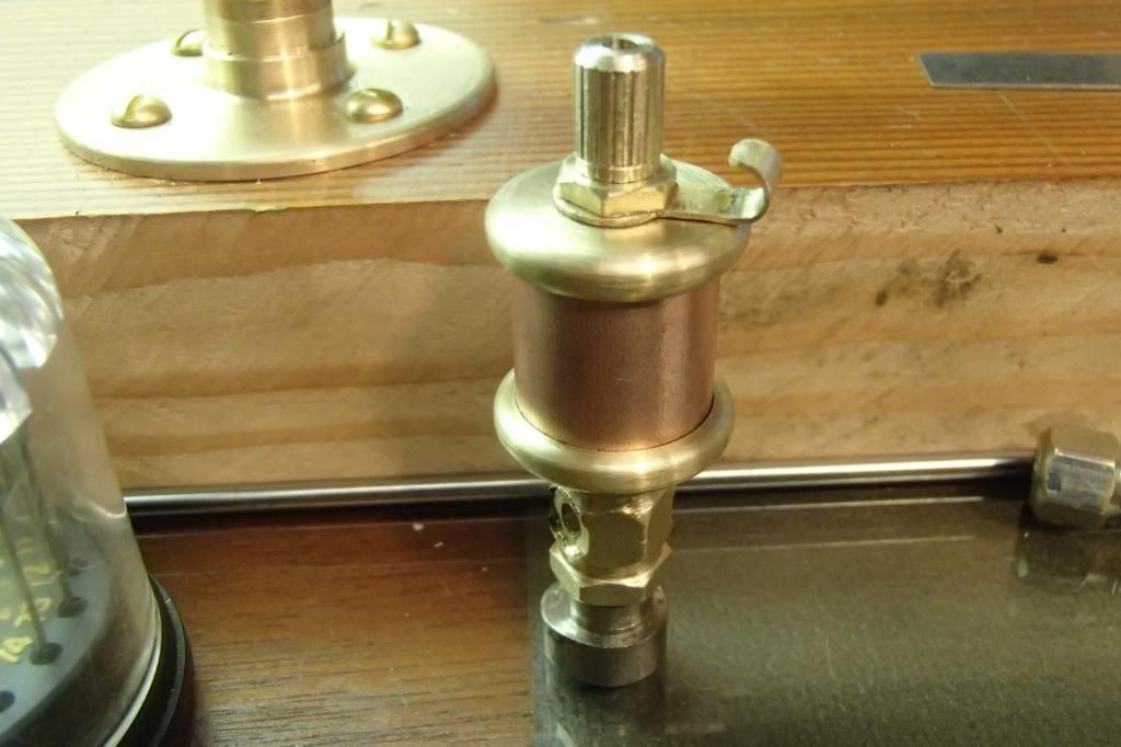
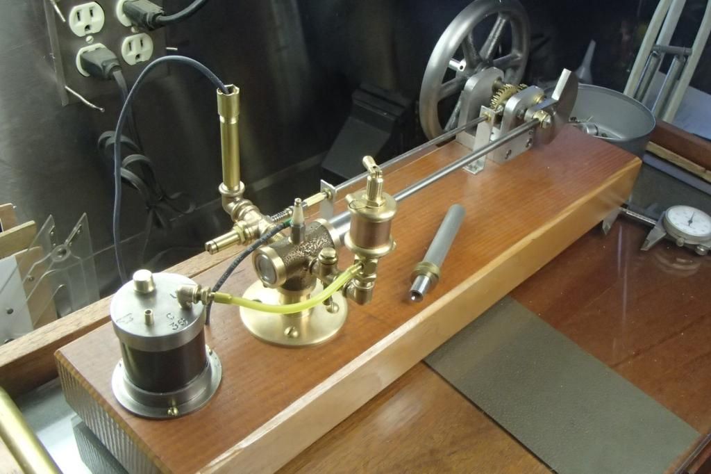
Faux oiler/mixer.


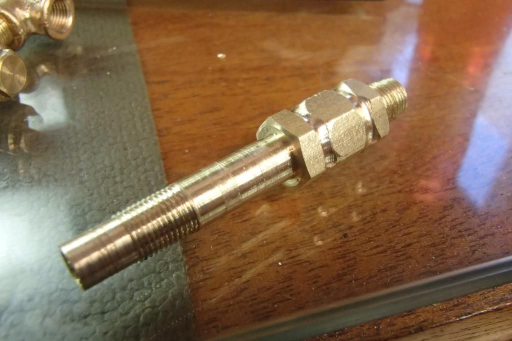
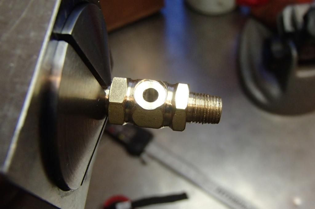
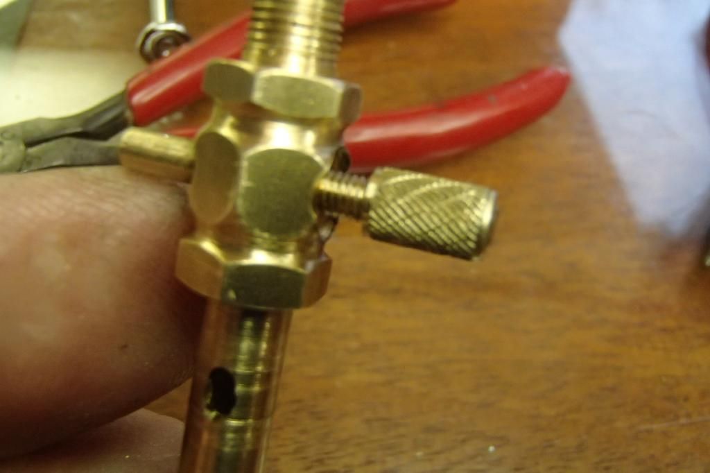
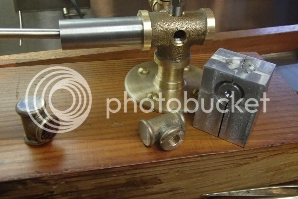
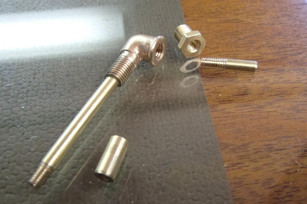
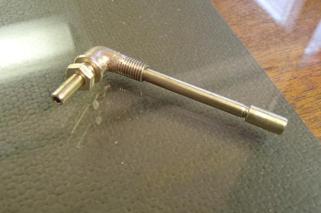
Starting with a length of 3/8 hex stock, the sight glass, threaded center tube and pipe thread nipple were shaped, somewhat modeled after a real size oiler I have. The oil reservoir will only serve as an air passage to the mixer which will be inserted thru the hole where the actual sight glass should be.


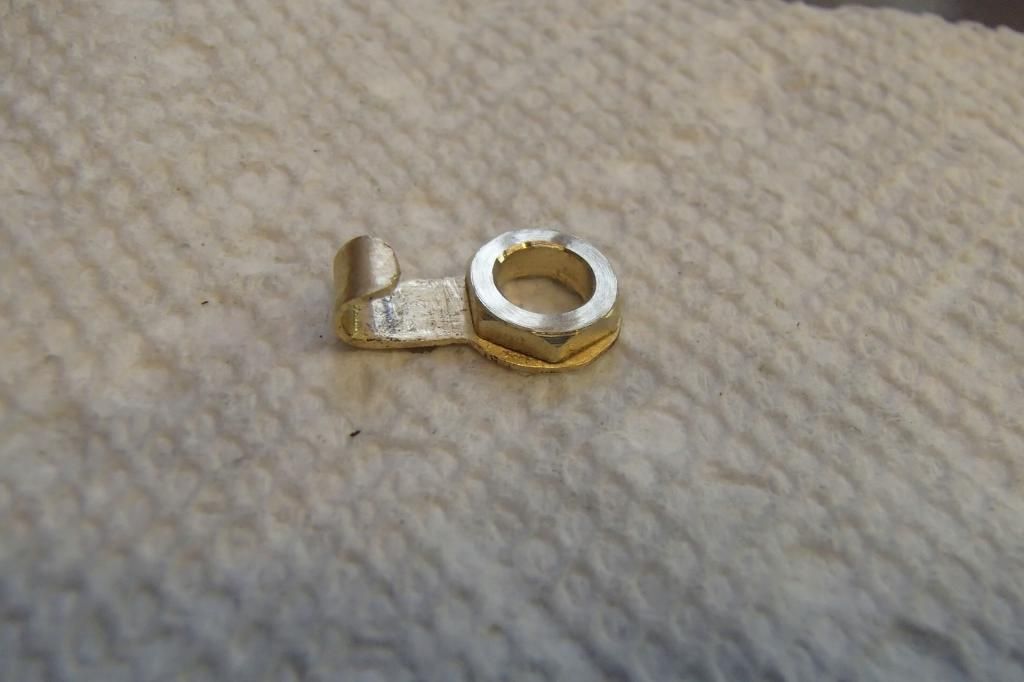
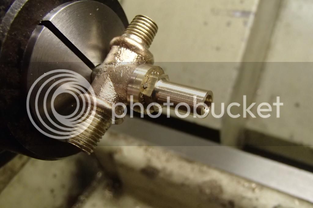
Next a swing type filler hole closer was 'hacked' out of a piece of brass sheet, also a fake hold down nut made. The closeup looks rough under magnification, but doesn't hurt my eyes too bad if I don't look to hard. This closer will act as my air adjuster/ choke.
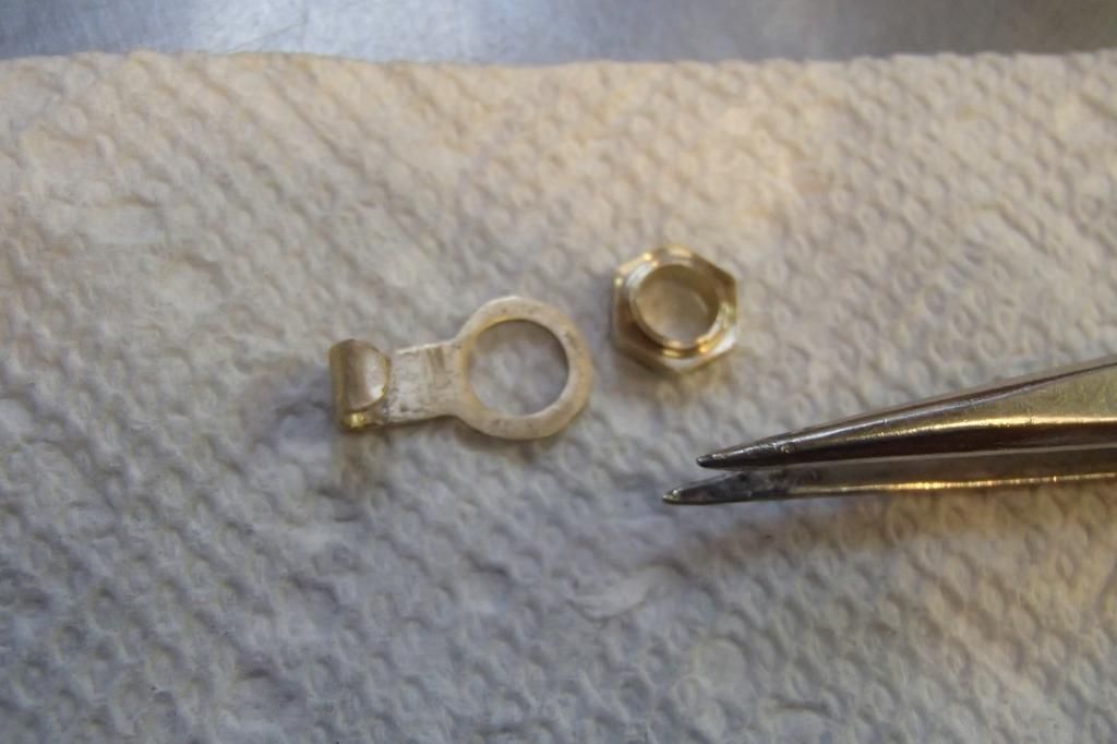


Then loctited together.


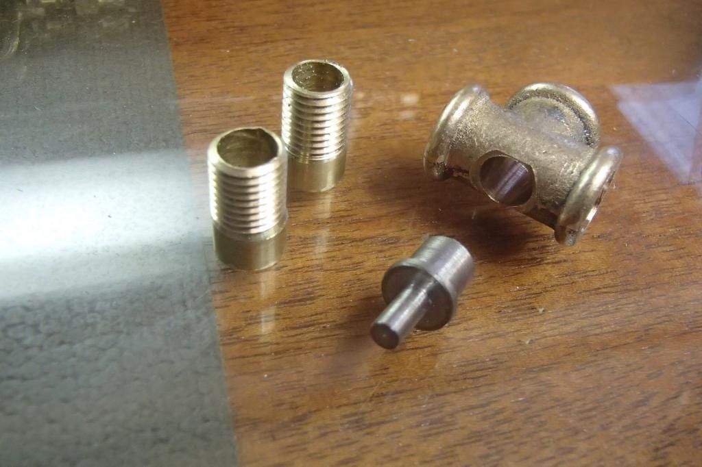
I made the top and bottom pieces earlier and forgot pics. I also substituted a length of 1/2” copper pipe for the glass. It may be permanent because the only 5/8” oiler glass I've found, seems too thick to work with my design. The top piece is threaded 1/4-40 to hold the oiler together.


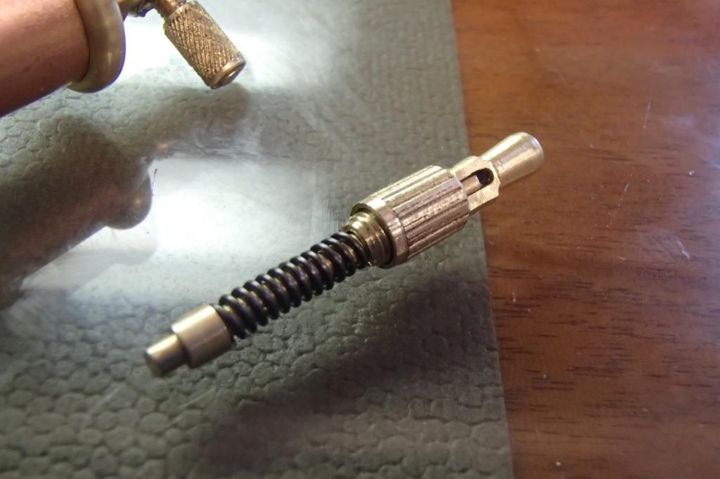
After a bit of thought I started work on the spring loaded the spring loaded valve opening lever, which will only serve to hold the hole closer from moving.


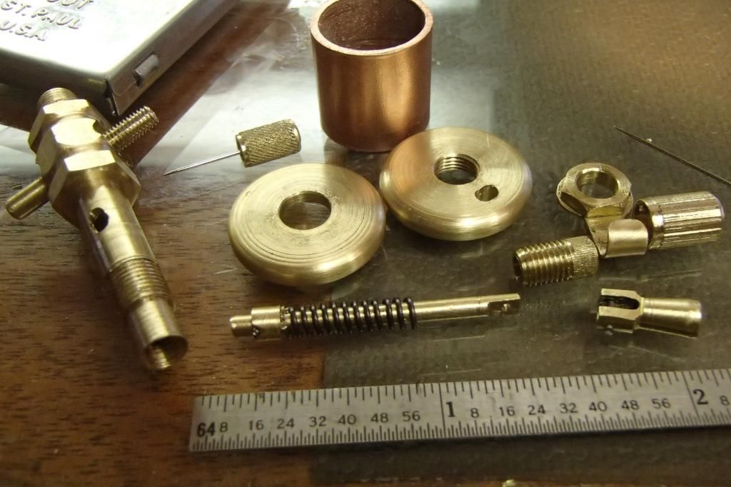
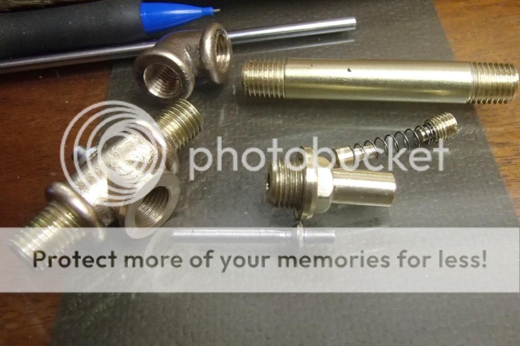
Here all of the pieces laid out. The knurled piece serves only to cover the the spring hold down nut.


10389


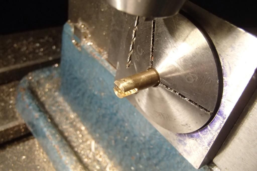
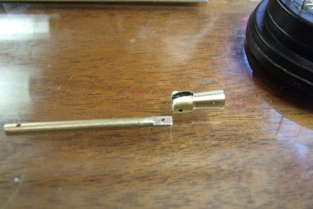
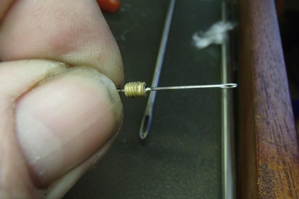
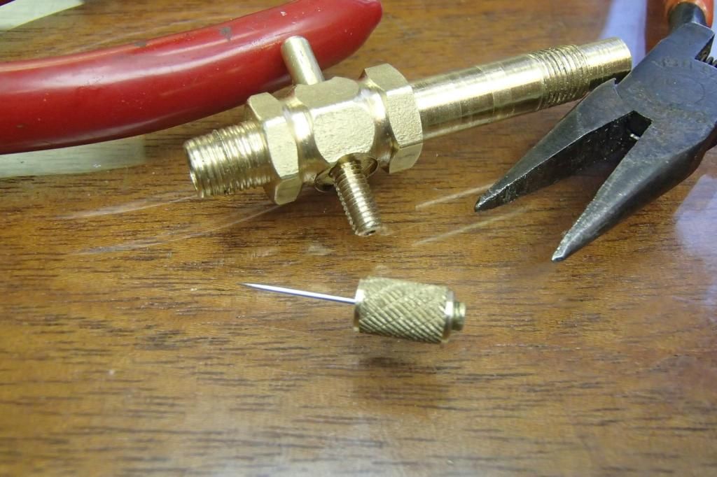
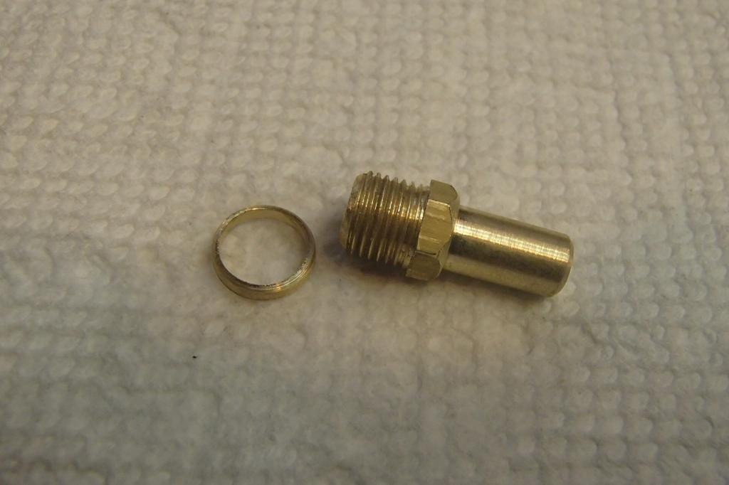
The needle valve body is 1/8” dia brass rod, drilled 1/32” partially thru from both ends and finished off with a #75 hole in the middle for the orifice. Seems a bit small to me, but I think it will be OK , if not I'll go a bit bigger, I'm only guessing.
One end threaded 5-48 for the needle holder/adjuster, the other end rounded a bit to accept the fuel tubing.


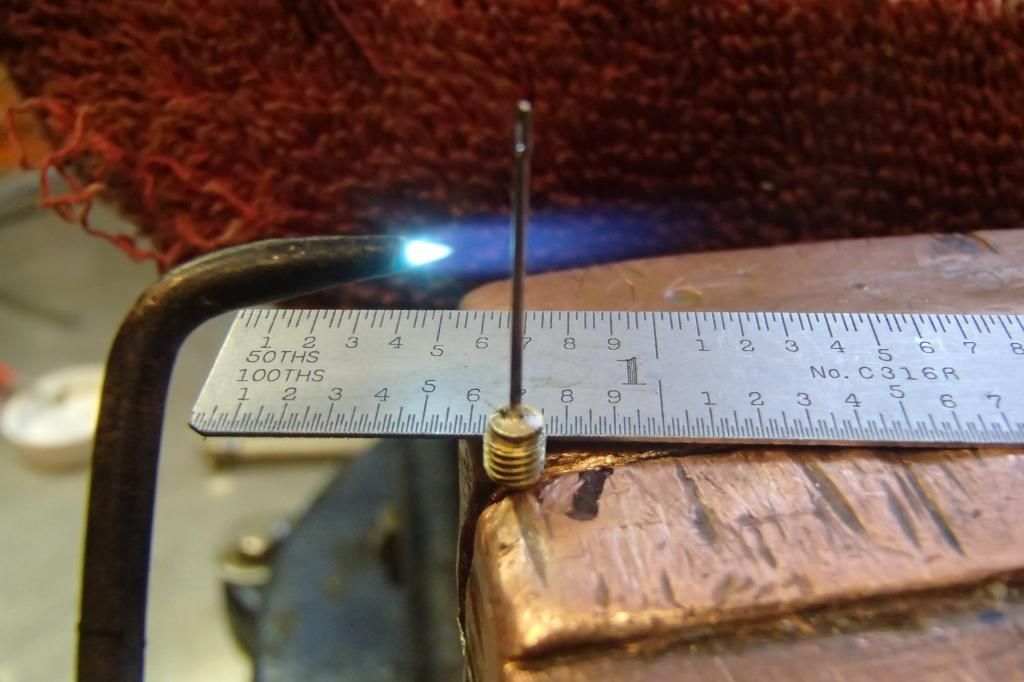
The needle is a.024” dia needle which will be silver soldered in the holder.

For the holder, a 3/16”dia brass bar drilled thru and tapped 5-48 then knurled and cut to length.
No real plan here, just making parts as I go.
The part that actually holds the needle is 1/8 rod threaded to match, with a .024 hole drilled thru, dimpled slightly at the end to help hold the solder and then cut off about an eighth inch long. The needle was pushed thru to approx. length and left long. This fit is very snug and will hold the needle in place while soldering. After soldering the piece will be threaded in and loctited in the end of the holder.


Before I committed to the length of the needle, the valve body was loctited into the sight glass and drilled thru at the size of the venturi. Then the needle fitted for length.


I ended up with quite a few parts for something I didn't think would be this involved.


Next in line will be the exhaust valve.


GUS
 
Wow Gus , You did already a very nice work. Kee it going on......

Barry
 
Fantastic job Gus. Looks authentic.

Thanks for posting all the pictures of your progress.

Cheers,
Phil
 
Thanks guys, I'm not to far out from getting this engine finished..

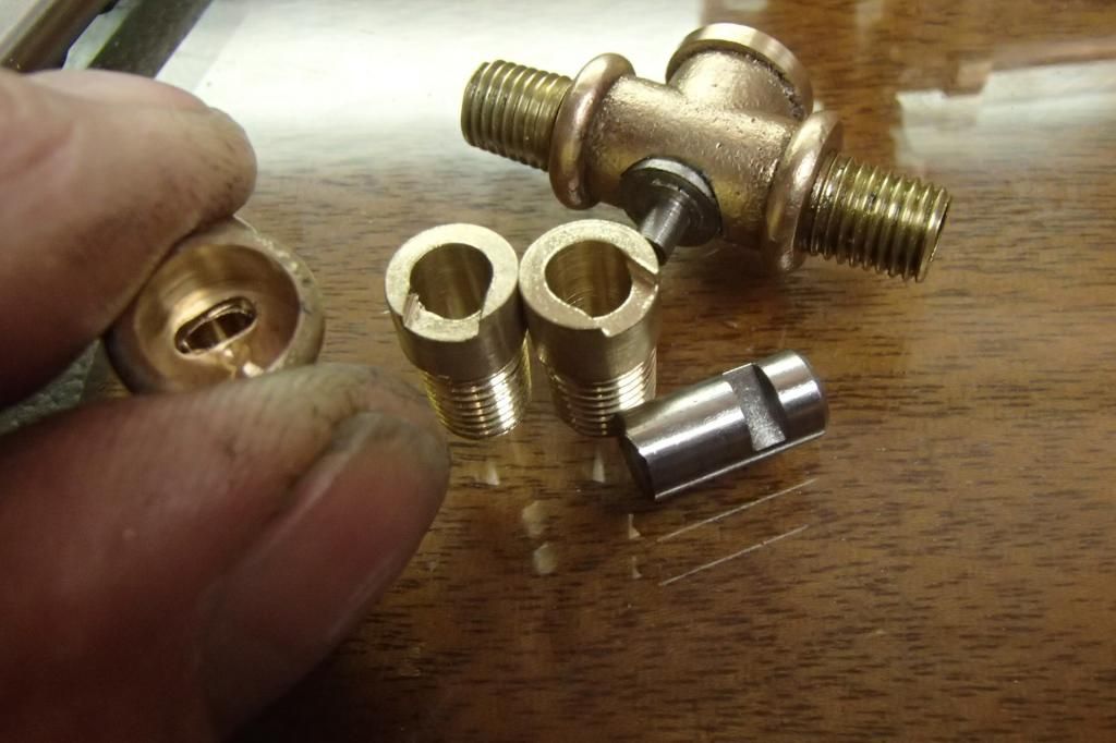
Construction of the exhaust valve is similar to the intake, with the exception that the fitting is 5/16-27 and the valve spring is enclosed in a tube on the top.


The assembly was to be:
Solder stub nipples and blank valve cage in place.
Then, in lathe chuck held by the exposed portion of the valve cage with spring assy blank in place, drill for the diameter for the spring to a depth just short of the bottom of the spring blank.
Then, the most important part, drill and ream thru the spring assy and the valve cage.
Remove spring assy and plunge cut the exhaust chamber in the valve cage with an end mill.


The importance of this “all in one” set up should help insure that the alignment of the top and bottom pieces would allow the upper and lower parts of the valve assy. to match concentrically.

That's what I should have done, but for some reason, I removed the piece from the lathe before I milled in the exhaust chamber. I saw no way that the concentricity could be maintained. The entire piece was ruined as far as I was concerned.
Concentricity was key and this problem was one that plagued me way back when I built the half scale model, and this “son of a ... problem” was no different.


I finished my day by sulking in the corner while sucking my thumb as well as a couple of brews. The next attempt would be better.
Next day, hope on hope, I decided that as long as I went thru this much trouble, go ahead and finish up, lap the valve in and cross my fingers that maybe the shop gnomes may have made everything OK, kind of like believing in the tooth fairy.
And, just like the tooth fairy thing, my hopes were dashed. Not only was the valve blowing bubbles badly, but there was air leaking out of the set screw that holds the spring in.

The next day I made all new parts and went at it again. This time changing the set screw to a screw with a sealing washer. Everything went well and now the valve was done except for cutting the valve seat and lapping the valves surfaces.

All was well again.


It wasn't until I installed the valve to the engine that I noticed that the valve was pigeon toed with respect to square alignment.


I wasn't sure what caused it at first but I remembered that while silver soldering the valve pieces together something strange happened. When I took the flame away the piece fell out of the Dremel vise I was holding it in.
It only took a little more thought to realize the nipple must have partially melted and squashed a little while soldering, as I was holding it by squeezing the nipples against the body.
A fairly easy fix was to mill the nipple out and soft solder a new piece in.


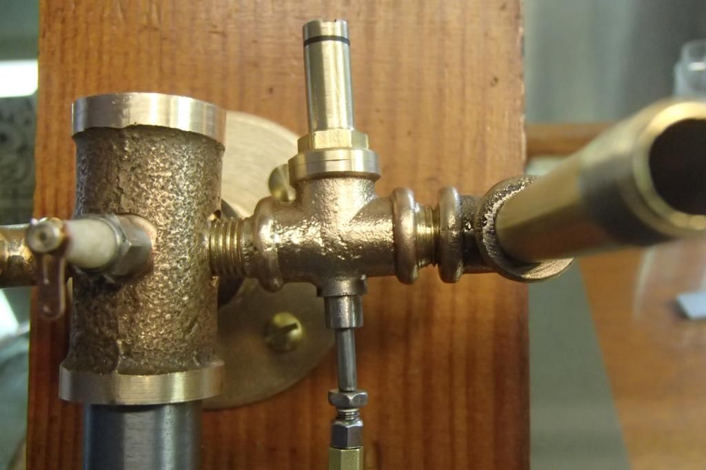
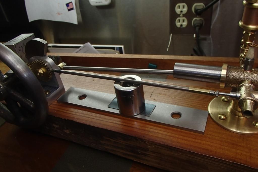
From there I moved on to start making the 1/8” dia. push rod and it's bushed mounting brackets.
Again departing just a bit from Henry's original design by adding an adjuster to it, also using only 2 brackets instead of 3.


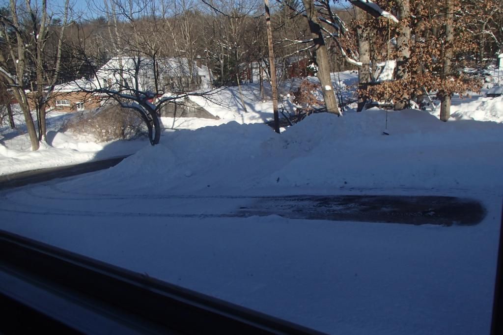
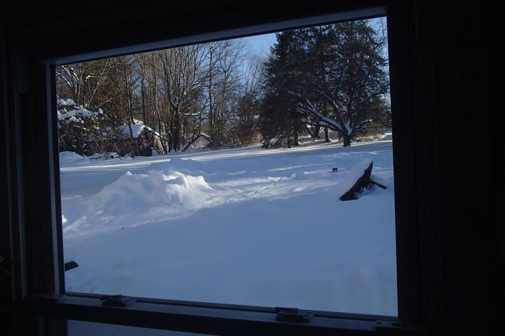
Right now, I'm at my computer looking out the window at the mountains of plowed snow in my yard it reminds me of Brian's comment, a while back, about snowmegedon, and Phil's pictures of his yard. Phil lives about 70 miles south of me.

This is what I see from here.​


And my backyard, where I had to plow around my well pipe so the repair guys could replace the submersible pump ( it just had to fail 3 days ago after being down there for 30 years or so).
On the right is the remains of my wishing well that was over the pipe, it was frozen into the ground and
sucumbed to the move. It snowed 6" more since then.


Now I'm hearing the TV warning of another storm coming tonight.:eek: Yeegads!! I'm running out of places to make more mountains and the snow is over my dogs head.
He can't even find a place to poop.
My daily routine has almost become to go out and plow last night's snow, go to bed and do the same thing the next day.
I'm thinking it's time to start shoveling the snow from the roofs, that oughta be fun.
Old man winter was kind and only dropped an inch last night.
I won't complain when this winter is over.

GUS
 
Last edited:
Gus,
The engine is looking good. I'll see it running soon?

The last winter of this kind was in 1994. Very unusual to have snow cover here for almost 3 months. I'm also running out pf places to put it and 2-4" more tonight:eek:

Cheers,
Phil
 
Looks like a piece of jewelry, Gus. Really nice work!

I've done that thing where I removed a piece from the lathe prematurely. Makes me want to kick myself every time. :rant:

Chuck
 
I'm really sorry this is a bit OT,

but Gus - I need to ask you about the spongebob squarebillet...
 
Top job as usual, Gus. We're back in t-shirts here but I could murder a good snowball fight :(


Sent from my iPod touch using Model Engines
 
Hi Phil, In real time the engine is pretty well finished and I'm still waiting on the gear cutters I ordered. The waiting gives me time to deal with the snow.
My son and I shoveled the snow from part of the shop roof yesterday afternoon. The part we shoveled kind of acts like a catch basin, collecting snow from the steeper pitch roofs on my century old multi additioned shop building. The snow there was near 3' deep.

Chuck, thanks for the comments. I've tried kicking myself, but couldn't reach that high, that's why I suck my thumb.:rolleyes:

Dave, t-shirts, lucky you. I'll mail you some snow.

Heffalump, I confess, I like Sponge Bob cartoons and all the silliness that goes with it. It's the only modern day cartoon I like.
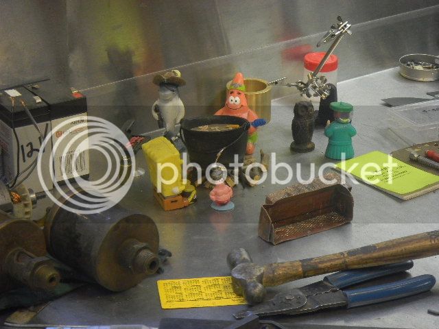
I also sit and watch old cartoons and the Three Stooges with my grandkids. I have a Three Stooges calendar in my shop, and also have some little friends I play with.

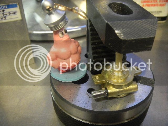
This is little Patrick. He's an ornery little dude and he's in charge of quality control and job safety.


This is the shop foreman Louie and his secretary Wooder.


This is some of the gang (there are more) having a beach party.
Here Sharky is cooking up some fresh caught people fingers on the grill, while the others have a good time around the fire. Yes, they all have names.


Sometimes my shop can get a little boring or I may be stumped by a problem or I'll hit a quiet time toward the end of my day. Stopping to play with my dog or my toys is another place to go.
I spend a lot of time there and a little company is a pleasure.
All that aside, a step away from the realities of life is good, for me at least, and there is still a kid locked up in this old body.;)
Be yourself, nobody else can do it for you.
GUS

Oh yeah, the billet. That's Sponge Bob Block Head. He's the newest addition, just anther one of my moments.
 
Last edited:
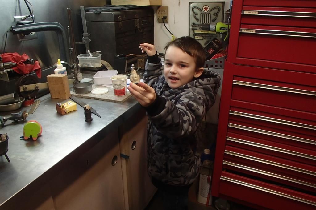
This is the other, also the real reason, I have the toys on the workbench.


That was yesterday. This my youngest (five years) of four grandkids.
They've all been right here playing over the years, the oldest is 17. It's a wonderful distraction.
For some reason the little guy decided to cover little Patrick with plumbers putty.:D

On the first picture, on the cabinet door, is a drawing the next youngest granddaughter made. It's a drawing of me and it says " Poppy, your like superman" She's 14 now and the drawing has been there quite a while and will stay there as long as I'm still shuffling around in there.

Oh yeah, they bring me the toys.

GUS
 
This is a small but important item and will be added to my “Plan Ahead”list.
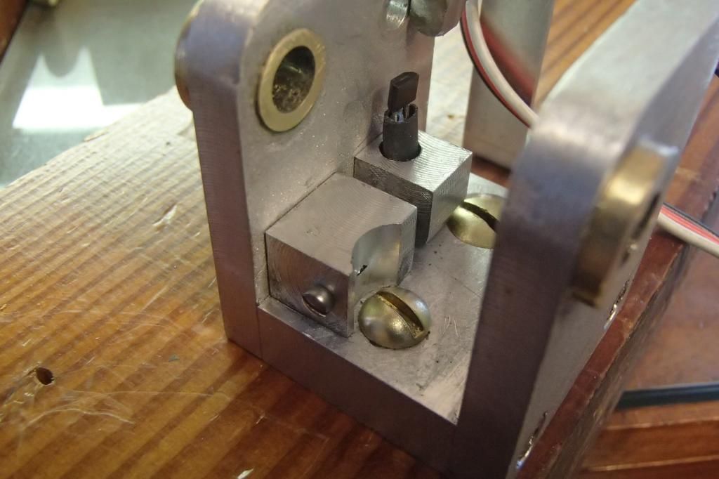
The Hall sensor holder/adjuster.
A simple alum configuration that would have fit nicely if I had not put the frame mounting screws dead center.
I made a quick sketch did a few operations and then had the “Oh Crap” moment when I set it in place.


The round head wood screws were in the way. I simply cut around one and replaced the other with a flat head so the moveable part could slide over.
Yeah, plan ahead, maybe.
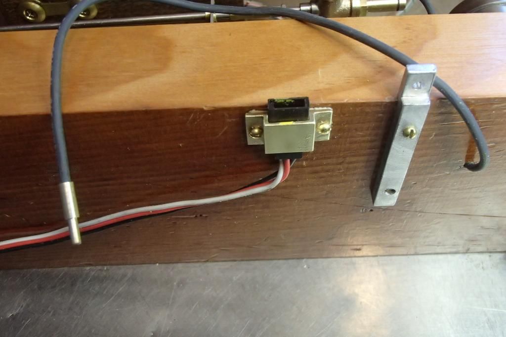
A simple holder for the sensor connector would complete the job. I liked the holder and made another half dozen more for my existing engines and would have some left for future projects as I really like the Hall system.
The alum. bar on the right is the grounding lug, and is connected to the cylinder base with a long screw.


Then it was time to set the ignition timing.
I adjusted the sensor to just under TDC, turned the flywheel a couple turns and the timing was off severely.
Reset it again with the same result and started to get the really big “OH CRAP” feeling.:fan:
The gears were not right. I miscounted the pinion teeth.
I was wondering why the gears meshed a bit tight, but put it off as a sloppy measurement.


These gears were, by my count, were 15: 30 tooth and I had on hand a pair of 20:40 tooth, but using those would entail building another frame, which was not in my agenda.
I would either have to buy another gear or maybe start thinking “gear making”
.
Making my own was the chosen path, and I got this discussion going on the “Questions and Answers” page. http://www.homemodelenginemachinist.com/f26/gear-cutter-help-22628/


I won't find out how that's going to work out for a bit, until I get the cutters I ordered.


GUS
 
Still tapping my fingers and waiting for my gear cutters to show up from wherever they should have been shipped from.


Last items will be the timing gear, fuel tank and finally sealing all the pipe connections.


I'm holding off the pipe connections for last as I want to test compression for individual components although the cylinder and piston seem to be where I want them as far as compression is concerned.


That leaves the full tank, which I've decided will be constructed of pipe fittings as I did on my half size H Ford.


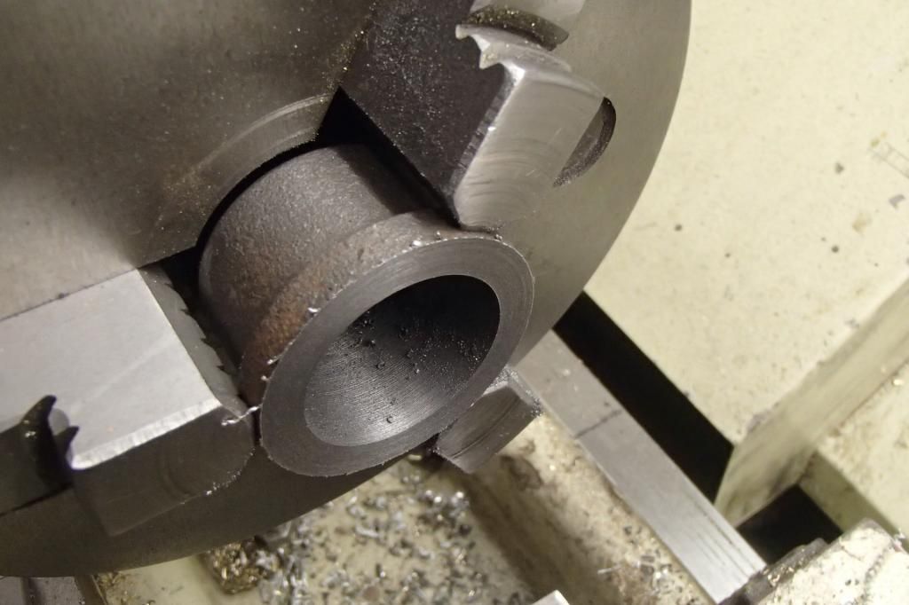
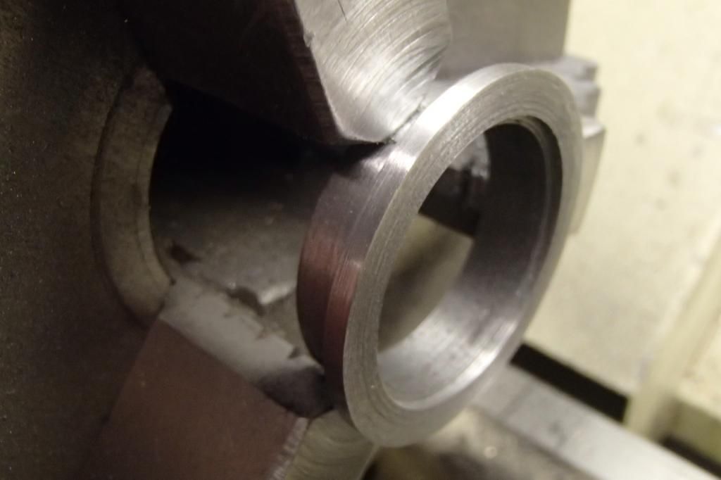
The tank base and top where cut from a 1” pipe cap.
In the lathe the cap was faced and then bored to slightly less than the OD of a 1” pipe.


Then turned around the body and top turned to reveal clean metal.


And parted off to form the top.
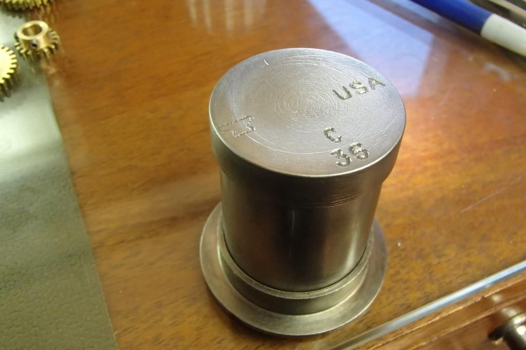
The remaining piece flipped again, the rim cleaned up and a step cut on the ID to receive the tank bottom which was cut from an iron bar and a temporary fit up made.
I'm liking the effect of leaving the manufactures marks on the top.


On to a bunch of pieces for the pickup tube/check valve parts, made based on a1/4” MPT street el. The check valve will incorporate a 1/16” check ball.


A fuel fill and vent pipe also made, the top then drilled and tapped appropriately and finally the assembly Loctited and installed.


And here it sits waiting for the gear, shown with the also waiting gear blanks.


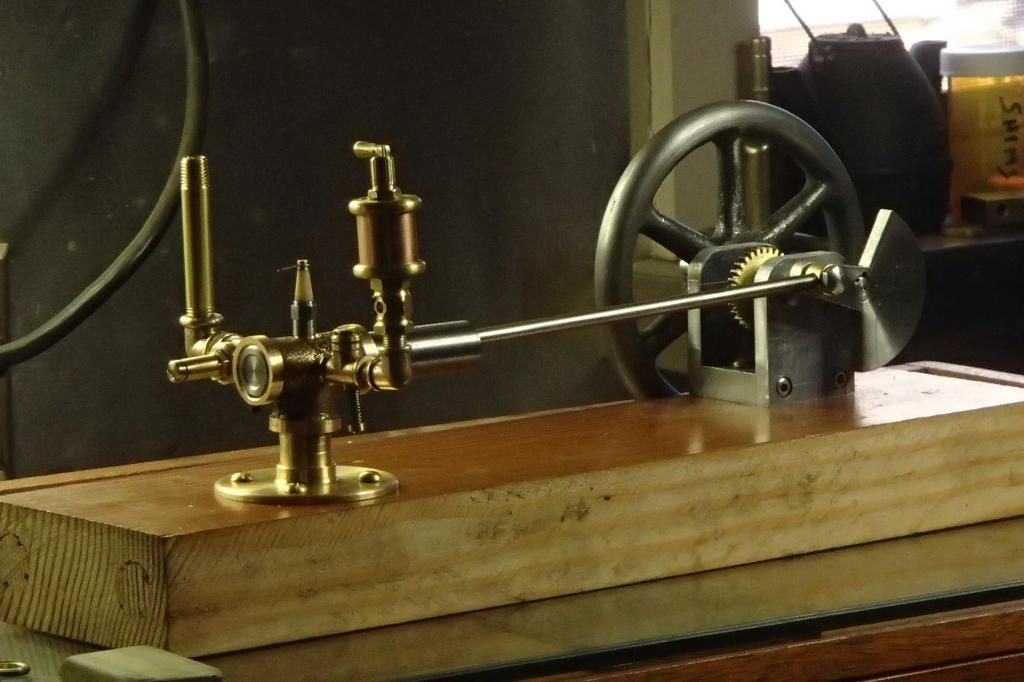
Engine now complete except the pinion timing gear and I'm bumping around cleaning the shop and revisiting the Wyvern and a few other open ended real size engine projects.


Gear cutter update, I ordered the gears from CTC on Feb 1.
Today Mar 13, still no cutters. So far my Email to them is unanswered. I'm not very hopeful about this.:(

GUS​
 
Gus,
I've checked my records with this vendor. I ordered my cutters on July 1, 2013 and they arrived on July 11, 2013. During that time we had traded a few emails about dimensions. This is the vendor:

http://stores.ebay.com/ctctools/

I hope this can be resolved soon.

Thanks for the update on your project

Cheers,
Phil
 
Does anyone know where to get plans for this?

So far there are no real plans for it, just a bunch of sketches and hieroglyphic looking notes. For my half scale, I merely scaled down the size using photos of the full size engine. For this 1/3 scale engine I scaled down the half size.
If someone would offer to do cad drawings and post them in plans forum, I would have no objection at all.
Some time ago there was a fellow in AU that contacted me and started to model the half scale, he did some preliminary work but must have lost interest.
If anyone wants to tackle the project, give me a holler. I'd be happy to scan and send the pages.


As for the missing gear cutters, it seems I was using the wrong email address.
I used the address from the info in my Paypal account. When I tried the address for customer service from their website just yesterday, I got this
reply this morning.

The goods have been shipped 5.Feb as registered postal airmail.The package number is RB324034245HK

I just checked at www.usps.com. They state "Origin Post is Preparing Shipment". At the Hong Kong Post web site http://app3.hongkongpost.hk/CGI/mt/enquiry.jsp they state "Destination - United States of America The item (RB324034245HK) left Hong Kong for its destination on 6-Feb-2014"

5.Feb we also had another shipment to a US client RB324034302HK. That one just showed up in the USPS system yesterday. We have enquired the USPS what happens and have been informed that the US Customs randomly pick international packages for inspection and keep them for some time. During that period the shipment is not visible to USPS. Since the other shipment just showed up then I suggest to give it one week. If the shipment still does not show up then we will ship a replacement. Should you end up receiving two packages then we will hold the cost of returning one of them back to Hong Kong

Best regards
Heine Johst
CTC Tools


I thank Mr Johst for that quick reply.
So, I'm just going to be patient and see what develops.
I have another little project that needs some attention.


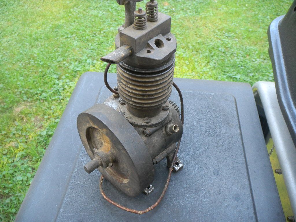
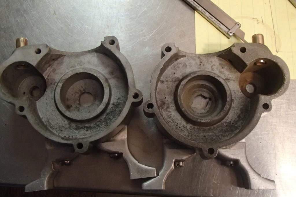
So far unidentified, my wife gave it to me at Christmas. She bought it from a friend of mine who bought it from a scrap yard. It was stuck, carb missing and a few other things.
I disassembled it and put it in the parts cleaner shortly thereafter.
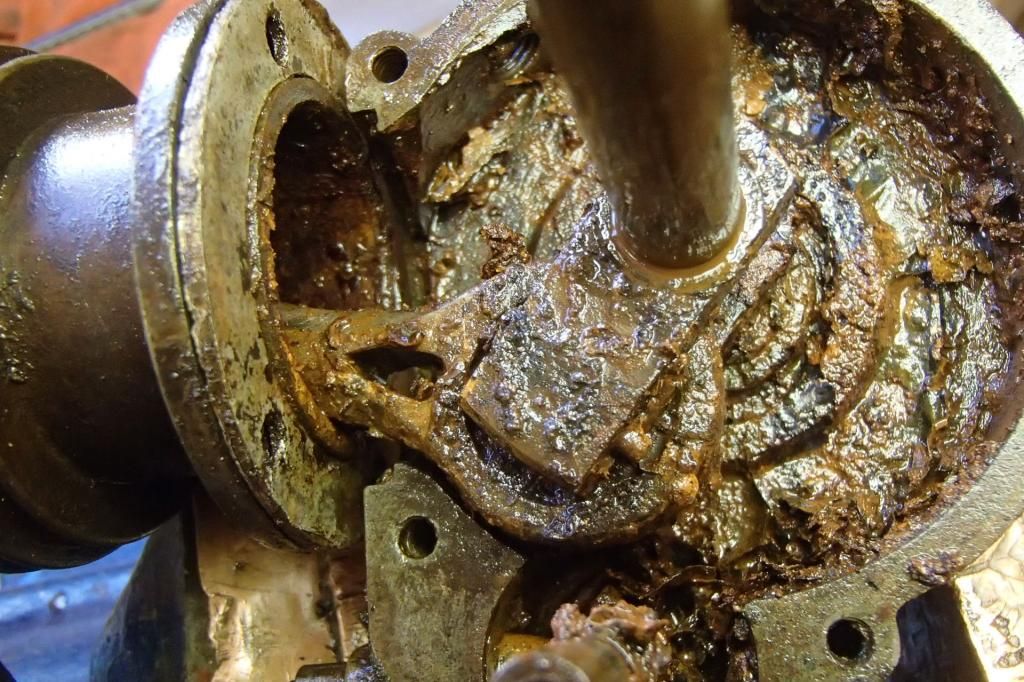
Pretty messy inside, lots of rust. It surely went through the great hurricane Agnes flood of 1972 that our area suffered.

It should fill the time lapse nicely. ;)
GUS
 
Hey Gus

I have been enjoying your work on Lil' Henry, lots of cool stuff here!

The new project looks like a fun one; I don't have any ideal what it is but I'm sure you will make it run.

Dave
 
Chuck, some similar works for me.
Dave, thanks, it's all fun stuff.

Being Lil' Henry is at a dead stand still, I'm going to hijack a page or two of my own thread.

I've been calling this engine 'The Unknown Christmas Present Model' , but being this new project is "some similar" to the 'Bill', I'm going to name it 'The William', at least until I find out what it is.

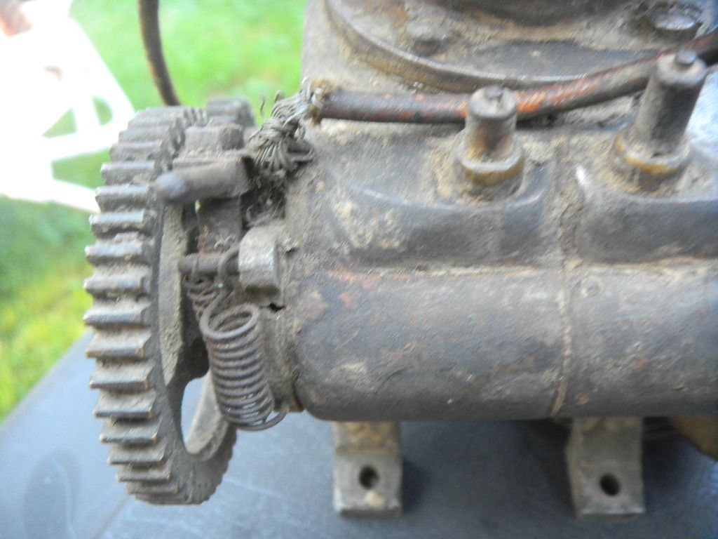
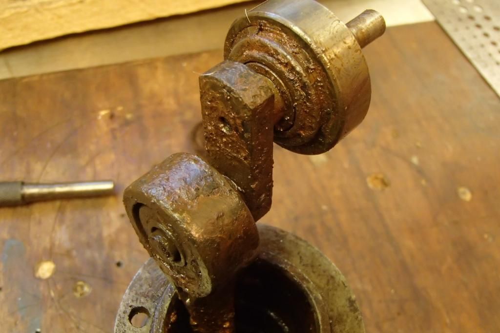
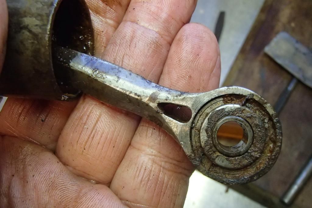
Here's a few pics of what I found inside after a few months sitting submerged in the sludge at the bottom of my parts washer.
If there are any children present, please have them leave the room.
This ain't real pretty.


Oddly, the only thing that succumbed during disassembly was the 1.5mm cast iron rings, they crumbled.

I'm not very sure it was a kit, unless it was an 'assemble it yourself' deal.
All enclosed New Departure metric size bearings, except the wrist pin which has a brass bushing.
The three piece crank is kind of neat.
No brainer is the bearings are all shot. Other wise the bore is nice except the bottom inch, which I think will hone out.
About 1 1/8" x 3" B & S, also metric. Flywheel and brass gears all pinned to the shafts.I'm thinking it came from across the pond.

I've opened up a few cans of worms in my time and that's exactly what this is.
But, what the hell, it was a Christmas present. I can't stop now. It should prove interesting.


GUS
 
Last edited:
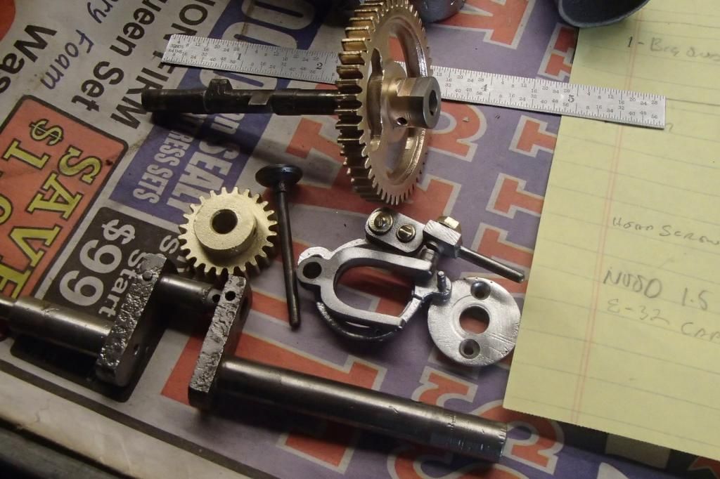
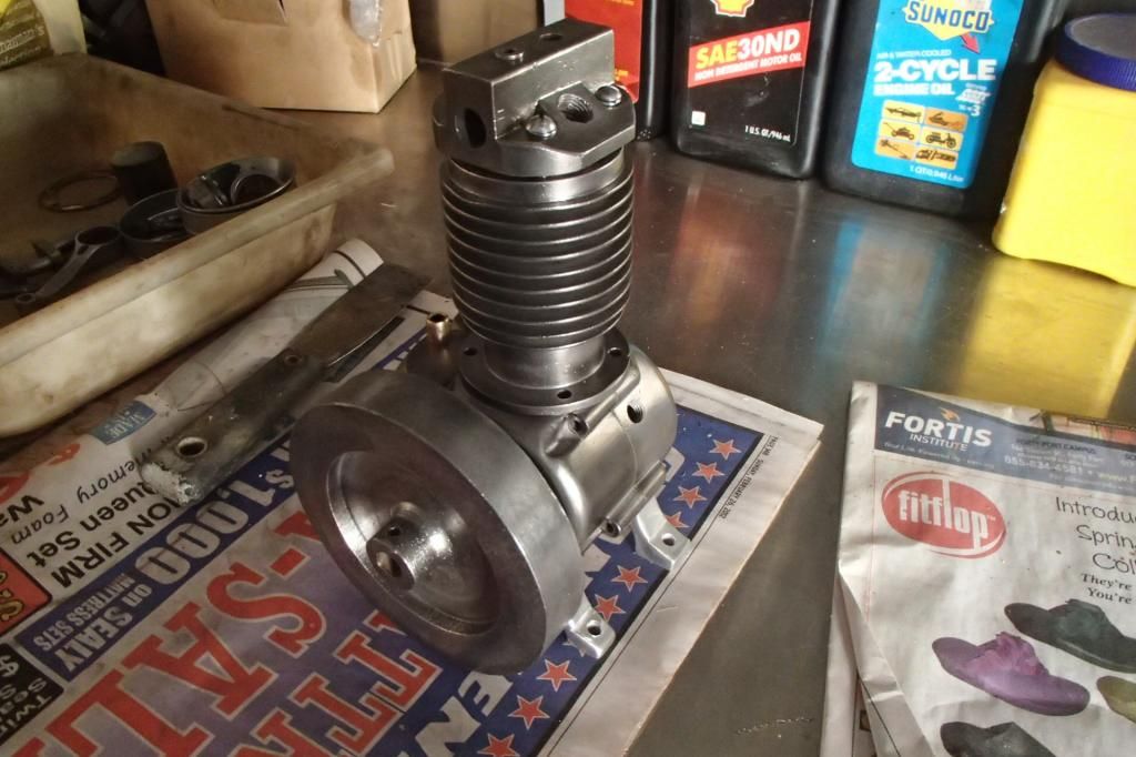
Still making good use of time waiting for the gear cutters, here's the results of a few hours worth of elbow grease on 'The William'.


This looks better to me and I'm now confident that 'The William' is very repairable.

Other good news is my gear cutters, finally, got delivered yesterday, which means I have work to do. :D

GUS
 
Back
Top