Kel's Poppin Double

Home Model Engine Machinist Forum

Help Support Home Model Engine Machinist Forum:

This site may earn a commission from merchant affiliate links, including eBay, Amazon, and others.
Arnold Kel,

My best looking parts are the ones that I make more than once. ;)

Thank you for the detailed procedures and good photos of your work.

You are performing some complex machining and I appreciate how much thought goes into it. scratch.gif

Thanks for sharing.

SAM
 
kcmillin said:
I made the slitting saw from a 1 1/2" round CRS bar. I mounted it on a mandrel in the lathe and turned it down to the final thickness. Then about a tenth inch in I recessed the sides to create clearance. You can see that in the picture.

Then I took the whole works, Mandrel and all, and mounted it on the R/T. From there I proceded to cut teeth like portrusions on the blank with an end mill. (I did not use any fancy angles, just what looked good) After I was done, I filed the cutting edges down to a sharp point. It works like a champ for cutting aluminum, brass and wood. (I used the mandrel I made to mount it in the mill also)


Hope this wasn't to vauge of an answer

Great answer. Thanks Kel.
 
Nice work Kel,

This looks an interesting one. I really needto get back onto mine :-\

Nick
 
That looks very good Kel Thm:!

And thank you for the idea on the slitting saw. I presume you are using relatively low spindle speeds with it ?
I have some case-hardening powder that I've been itching to try out, and a saw like yours could really work with that!

Regards, Arnold

Uhmm Sam - Thanks :) - Kel's thread though ;) - he does not re-make parts as often as I have to, so much better to learn from :)
 
Thanks Sam, Zee, Nick, Arnold, and Marv.

Sam, I think you got the wrong thread. Thanks anyway though.


Nick, I would really like to see yours get finished. Have you found a new vice yet?

Arnold, thanks for the kind words, although My work isn't without its mishaps. I have been pretty lucky with this one. :hDe:
The saw I made does work great but I think Marvs Idea for using a wood saw is a even better.


Marv, wow I never thought of that, I have used a circular saw to cut through alluminum channel. but never thought to put one in the mill.

$6 < two hours of work............. ya I think Ill go your rout.

Thanks everyone again.

Kel
 
Marv, wow I never thought of that, I have used a circular saw to cut through alluminum channel. but never thought to put one in the mill.

$6 < two hours of work............. ya I think Ill go your rout.

There's a picture and a few words here...

http://www.homemodelenginemachinist.com/index.php?topic=1952.msg15740#msg15740

While I use it for typical slitting saw tasks, it's also useful for sizing stock too small or awkwardly shaped to be held in the horizontal bandsaw.

So far I haven't broken one but, even if I do, it's pretty cheap to replace.

Take the time to build the holding arbor with the recessed lock screw so you can get down close to the table surface. You'll thank yourself the first time you need to do that.
 
Well, I got a few more parts done in the last couple days.

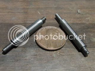
First is the two valve rods.
CIMG0972.jpg


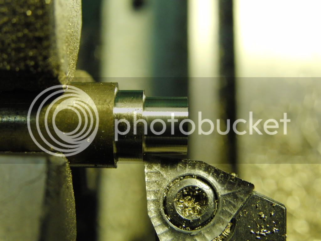
Next up was the four bushings for the valve rods.

I just got about $600 worth of indexable tooling and holders. This is the first time I got to make something with them.

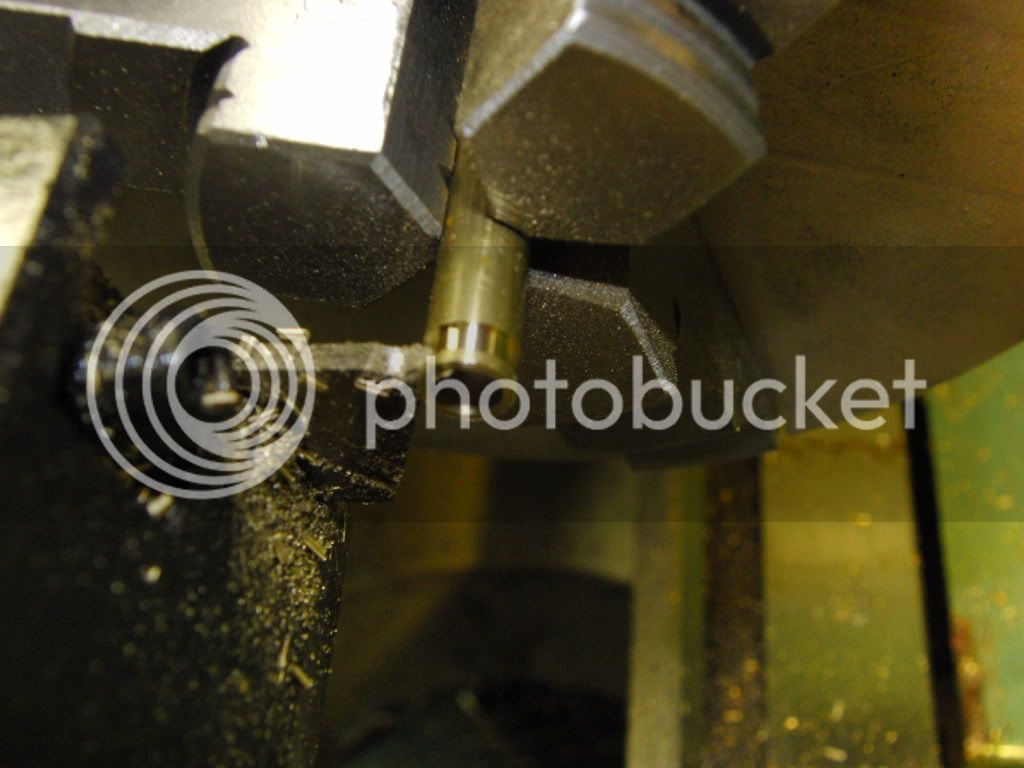
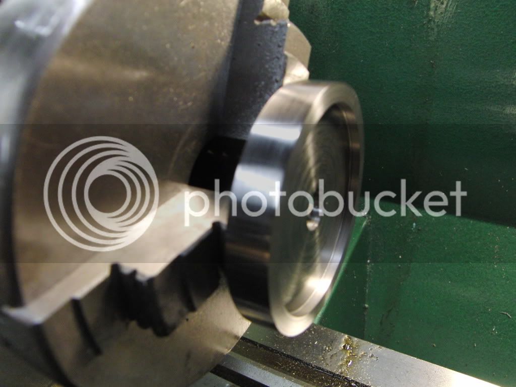
This was in particular makes a very fine surface.
CIMG0934.jpg


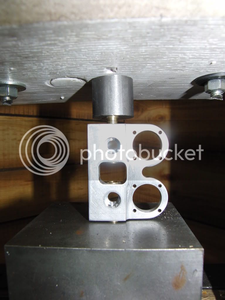
Here I am pressing the bushings into their respective holes with my homemade wooden shop press.
CIMG0948.jpg


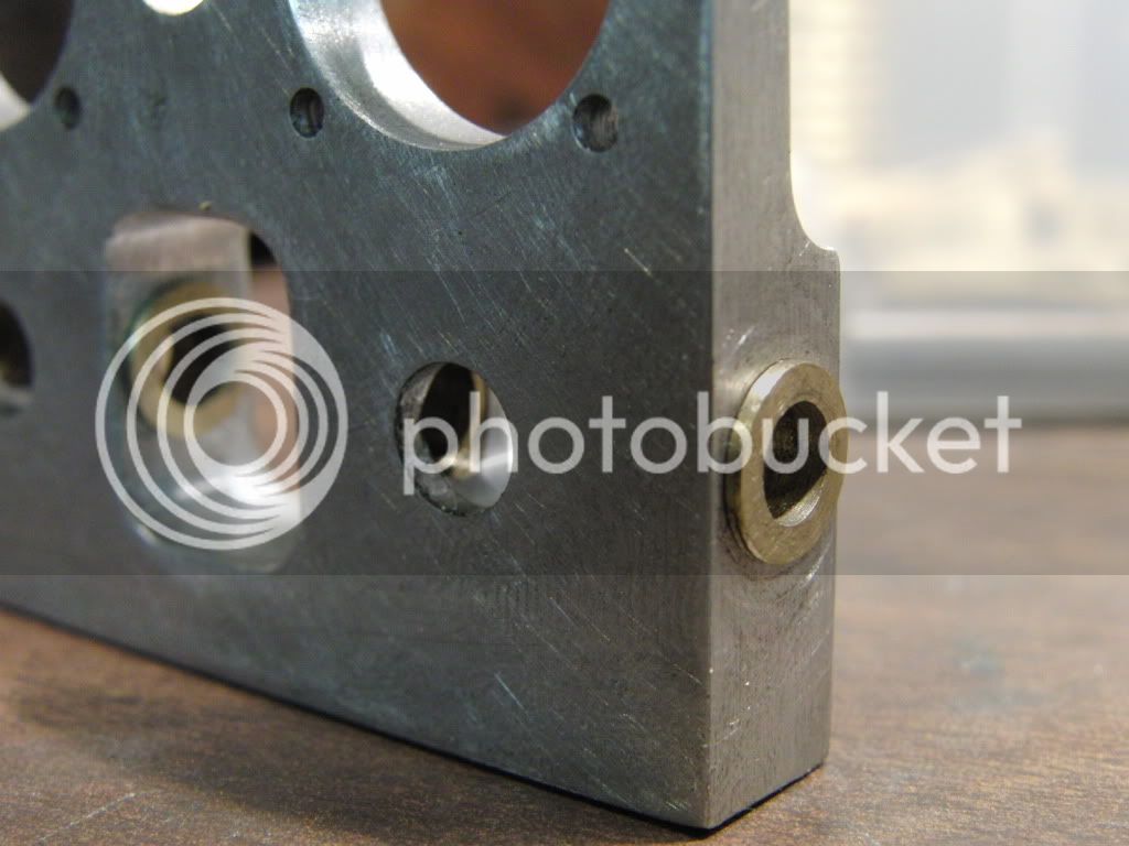
Here is a shot of the installed bushings.
CIMG0973.jpg


Next up Its time to make the crankshaft.

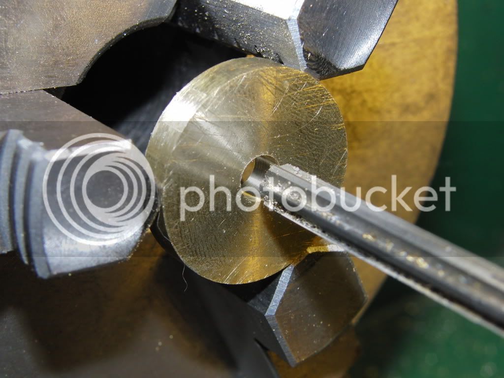
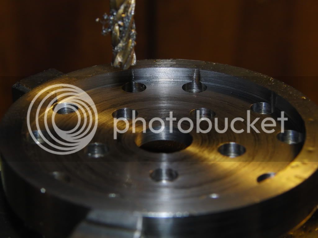
I started by making 4 disks out of brass with a 1/4 hole drilled in the center.
CIMG0958.jpg


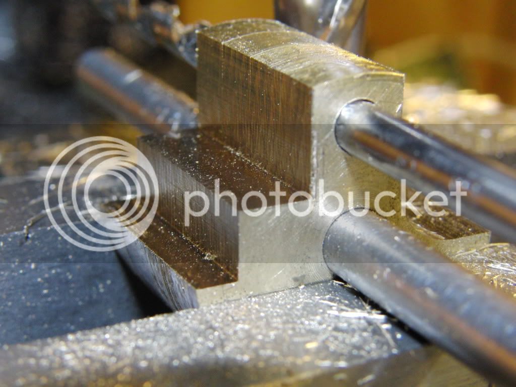
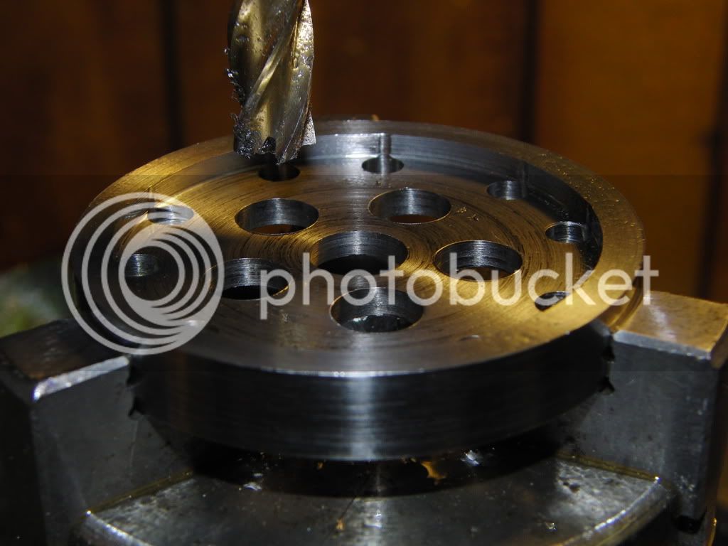
After drilling the throw holes, (sorry no pics) I mounted all four in the vice with rods through both holes to line them up.

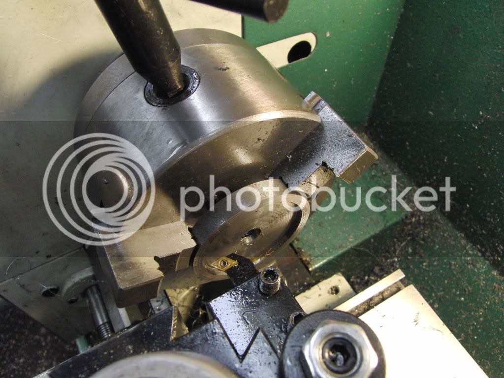
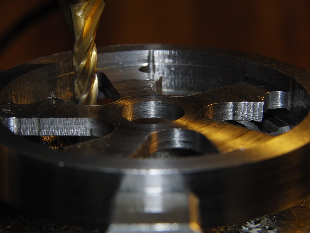
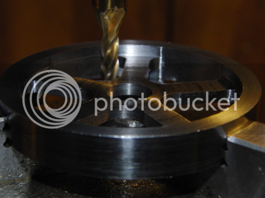
I first cut most the material out with a regular and mill.
CIMG0961.jpg


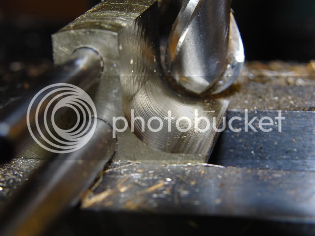
Then I used a 1/2" ball end mill to make a radius.
CIMG0959.jpg


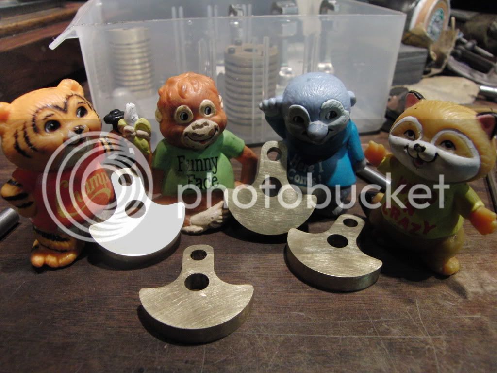
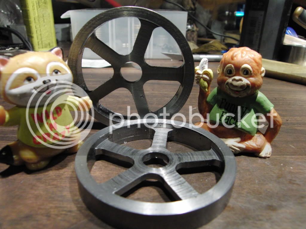
Here are the finished crank webs hangin' out with the gang.
CIMG0975.jpg


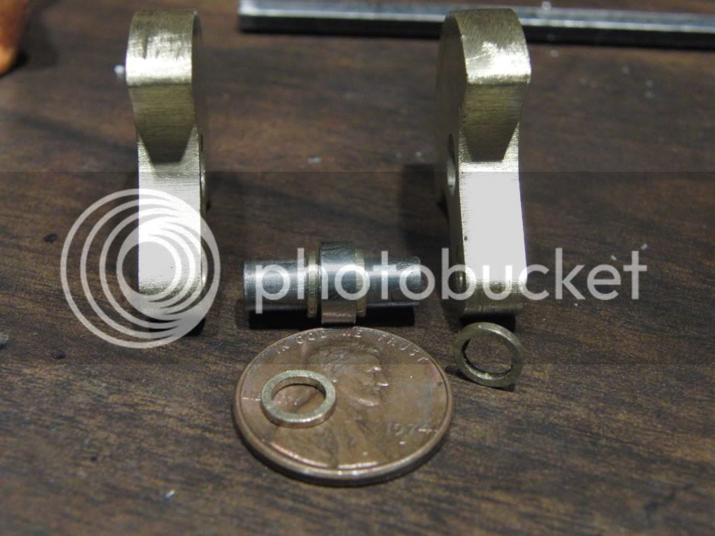
Next up I had to make some spacers for the bearing on the crank throw.
Here is a pic of me parting them off. (they are .035" thick)
CIMG0969.jpg


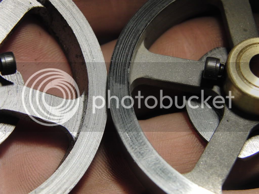
Here is a shot of the crank web and bearing assembly before pressing together.
CIMG0971.jpg


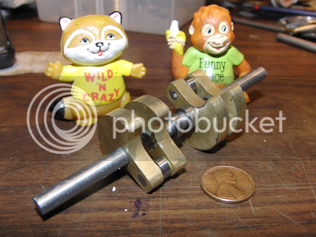
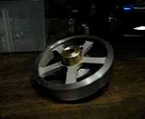
and the finished crankshaft. (sorry no pics of the pressing process)

CIMG0976.jpg


Thats it for now.

Kel
 
I sure like the way to do things, Kel. Your crankshaft came out really nice!
Just something I thought was kind of funny in your thread; The one little figure in the
shot of the crank throws has a shadow across part of its 'shirt' making the name look
like "Chump". I had to get a second opinion from my bifocals. ;)

Marv, thanks for the tip on the saw blade. I see in your linked post that the kerf is .050".
Pretty handy.

Keep up the good work, Kel!

Dean
 
Deanofid said:
The one little figure in the
shot of the crank throws has a shadow across part of its 'shirt' making the name look
like "Chump". I had to get a second opinion from my bifocals. ;)
Dean

That is funny.

I thought the same thing after posting.

I found these guys in my "Box of Memories" I had to look on the internet to confirm my suspicions of who they were. I found out that they are from a cartoon called "Shirt Tales", I remember very little of this show, aside from the fact that "Punky Brewster" was on around the same time. Ah....The weird things we remember.

Kel
 
Kel,

Nice crankshaft.

Sorry about the mix up between you and Arnold.

SAM
 
Thanks Sam and Vic for your comments.

I Did have a slight problem with the crank after I installed it into the bearing supports. I had a bit of a wobble when I turned it, and it was binding in the bearings.

I managed to get the wobble out of the ends of the crank, but I still have a wobble in the center. There are two bearings which are permanently installed in this space.

I am not sure what I am going to do with it yet. I have thought about breaking the bearings off and just not having them. It runs over quite smooth without the middle bearing support installed.


Kel
 
Thanks for the encouragement Bogs. I am thinking about removing the bearings, but installing the bearing support to make it appear that there is something there.


I decided to start work on the flywheels.

I am making them from 2 1/2" steel. They will have a small rim and five spokes.

I have attempted making five spoke rims in the past, and for the most part they were a haphazard just do it approach. But this time I decided to do nit a little different. (for me that is)

I have a 2D drafting program that is excellent for finding dimensions. So I just drew it up, and found all the hole locations and correct degrees for the R/T.


First I had to make the blanks. mostly straight forward lathe operation.
CIMG0983.jpg


To do the rim, I put the inside jaws on the chuck and held it from inside the rim.
CIMG0984.jpg


Next up, drilling all the holes, I kinda screwed up and got to close to the rim.
CIMG0987.jpg


Now making the inner holes larger. Due to the limited clearance I used an end mill to make all the holes finished size.
CIMG0989.jpg


Now I offset the X and proceeded to cut out the spokes with a 3/16 end mill.
CIMG0992.jpg


Flip the X offset to the other side and finish up the millin.
CIMG0993.jpg


And here they are, blems and all.
CIMG1001.jpg


I plan on sandblasting the spokes to give it a frosty look. (plus then I get to try out my seldom used sandblasting cabinet.

Kel
 
Nice job, Kel!
These look very good. :bow:
Do you care for the mark on the rim? or is the sandblasting going to mask it?
I have never seen a sandblasting procedure... will google...

take care,
tom
 
Thanks Tom.

The marks on the rim will be removed with alot of file work. once The lines are out I will sandblast it.

Kel
 
Kel,

Nice flywheels. I need to try and make a spoked flywheel.

I noticed that you forgot to remove the chuck wrench in one of your shots.

A neighbor of my taught me that a chuck wrench is always attached to your hand unless you are putting it away. th_rulze

Safe Regards,

SAM
 
Sam, ya that wasn't smart of me huh. In my defense I had put the flywheel back in just to take the picture. Only temporary. :hDe:

Kel
 
Well I got my blast cabinet in from the garage and I found the media to be quite damp. I gonna have to find a way to dry it, or just replace it. It probobly needs it anyway. It was not working the best, but I did manage to get a quasi finish on th spokes.

Here is a pic of before and after. It still needs some more work though.
CIMG1053.jpg


and a quick vid of it in "Action"


Kel
 
Back
Top