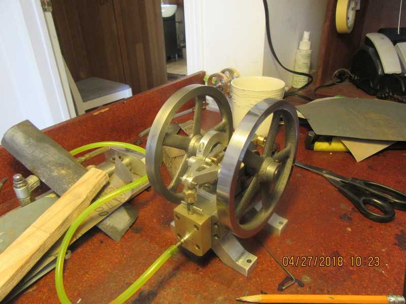
Inspiration for new air motor

Home Model Engine Machinist Forum

Help Support Home Model Engine Machinist Forum:

This site may earn a commission from merchant affiliate links, including eBay, Amazon, and others.
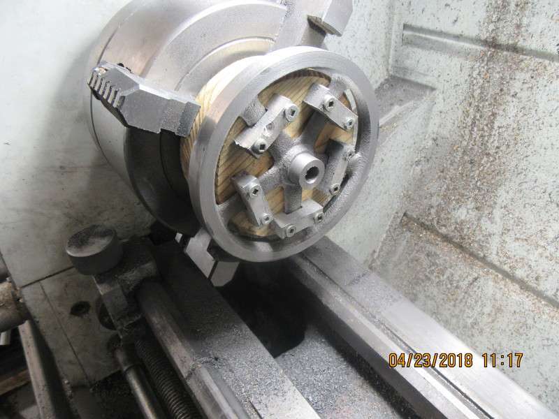
Just finished machining flywheel #1.-A totally different experience!!! I have never machined a casting before. My lathe and I are both dirtier than a pig from iron dust. The picture I posted earlier of my proposed set-up seemed to work very well. I can't get over how far out many parts of the casting were from the finished ideal, although I understand that is typical with sand cast parts. In this one set-up I was able to machine the outer face of the flywheel, both sides of the rim, cut off and true up the outer diameter of the hub, and finish the bore. All that remains is to flip the flywheel around and hold it by the outer rim in the chuck to face the far side hub.
vsb7fh.jpg
 
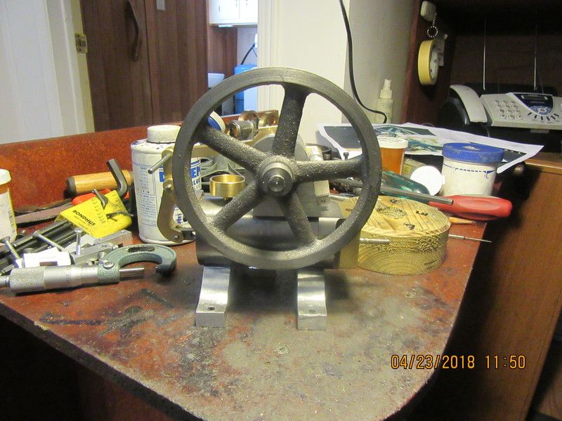
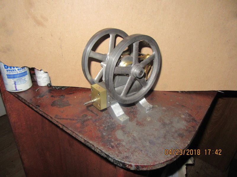
Not hard work, just a lot of work. and it's something new that I haven't done before. Both flywheels are fully machined except for the set screws. I am going to have to spend some quality time with my Dremel tool to clean up flash lines between the spokes, but overall I'm happy with my results. I also have to figure out how the guy who's flame-eater inspired this build got the machined areas of his flywheels so shiny.
j16pa5.jpg
 
And now---Here's the rest of the story. I machined everything with an HSS tool, with the lathe running at 200 rpm. Most of the time my depth of cut was 0.010". The flywheels cleaned up at 4.950" outer diameter, 0.472" wide, with 0.70" diameter hubs, and of course I drilled and reamed 0.375" center-holes to match the crankshaft. The original castings were 5.1" diameter x 0.520" wide. I only machined enough away from each surface to get past the casting finish.---Brian
 
Machined cast iron should come out almost like chrome.
I use different grades of steel wool to obtain such finishes, and not only on flywheels, but it is a bit dicey as your fingers get very close to spinning parts.

If you can get or make yourself a small die filer, spokes on flywheels can be cleaned up in minutes. A very underated machine.

John
 
I've whittled this thing down to the point where there are only two pieces left to make before I can try to run it. I need the 1/4" diameter valve and the link that attaches to it, but I'm too tired tonight to make anything. I started the valve this morning before I had to go across town on one of my "real" design jobs, then promptly screwed it up when I returned home this evening. But--Tomorrow is either going to be really exciting or else very disappointing. I'm still not 100% certain that I have the valve designed properly, but it's basically a "cut and paste" of the valve I built a few years ago when I redone the Chuck Fellows engine. I can paint and polish things after I know the engine is going to run.
 
I machined everything with an HSS tool, with the lathe running at 200 rpm.

That is 260 ft/min on the rim. The recommended speed for HSS tools on grey iron is about 60 ft/min (depending very much on who is doing the recommending).

To finish cast iron I use silicon carbide paper and kerozene, with the paper wrapped round something flat, like a file with a sound handle, so as to avoid the mortal sin of rounding the crisp geometry.

Your side of the pond people generally seem to go for a far higher degree of shine than would be considered good taste here, where going mad with a buffing wheel is reserved for bits of motorbike.
 
Well, we didn't quite get there today, but we got awfully close. I have two gaskets to make and I have to set the valve timing, but other than that I think I'm ready for a trial run.----Tomorrow
[ame]https://www.youtube.com/watch?v=58RaNBUE09I[/ame]
 
so the brass arm riding on the eccentric is what is running the valve right? held on the pivit pin via a set screw?
its looking very nice.
looking forward to the test run.
 
Morning has come, my gaskets are made, my engine is timed, but it won't run. OH POOP!!! Howevah--if I disconnect the link which runs from the Y shaped yoke and lift/lower the actual valve "by hand" I can find one position where
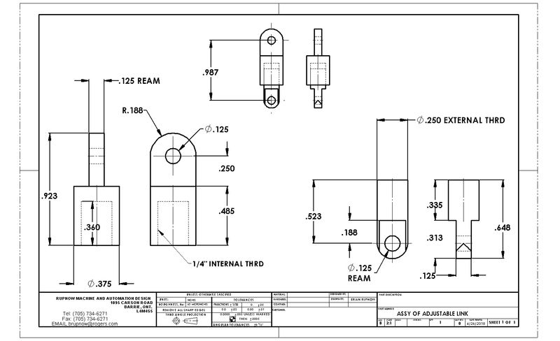
air is being passed to the cylinder (and this thing is strong considering the 7/8" bore), and one position where no air is being passed to the cylinder. This may simply be a matter of tailoring the length of the link so the two positions I found "by hand"correspond with the max/min positions of the yoke. Maybe an adjustable length link until I find the "sweet spot".
 
So--all it took was a little bit of patience and a bit of luck, and Hey Presto--We have a running engine. It's beautiful!!! I have painting and polishing yet to do, but the design is proven. I will be selling the plans to this engine for $25 Canadian funds. Thank you for all sticking with me through the build.---Brian
[ame]https://www.youtube.com/watch?v=zDU2BIC701c&feature=youtu.be[/ame]
 
Now here is a very interesting shot. I gathered up all the random pieces of sandpaper I could find, and mounted the flywheel on a 3/8" arbor and put the arbor in my lathe. With the lathe rotating at 250 rpm. and working on the face only, I first wrapped #180 grit paper around a flat stick and held it against the rotating face. I kept the stick and sandpaper moving a bit, for a slow count of 50. Then I repeated with 220 grit, always keeping the stick and sandpaper moving just a bit for another count of 50. Then I repeated with 400 grit, then with 1500 grit, then with a pad of "ultra-fine" Scotchbrite held in my hand--no stick. The face had by that time taken on a mirror like finish. I was so pleased with this that I then done exactly the same thing to both sides. At this stage I have not used any buffing wheels nor compound.
sxtnon.jpg
 

Latest posts

Back
Top