Indicator Holders and Such...

Home Model Engine Machinist Forum

Help Support Home Model Engine Machinist Forum:

This site may earn a commission from merchant affiliate links, including eBay, Amazon, and others.
Thanks Robert. I'll have to try Sketchup again. See what I can do with it.

Marv has a good round-over tool too. Uses an end-mill if I remember. Someday I'll have to make one. I'm thinking the end-mill would be better about keeping out abrasive?

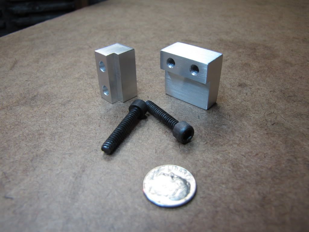
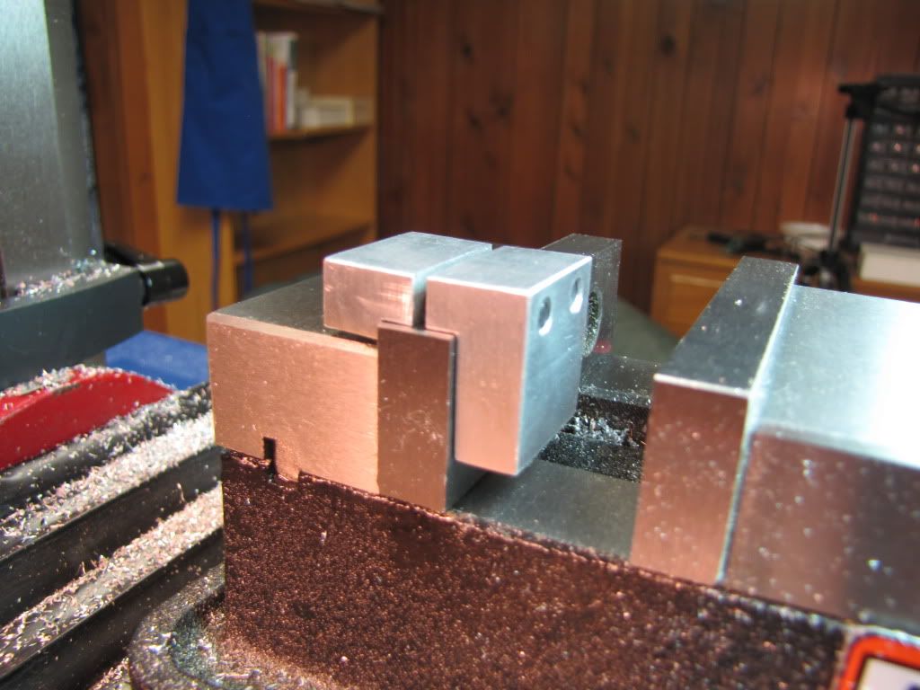
So here's the vise stop so far. Next step are the holes for the two screws. The bigger piece will be threaded. The other not.
IMG_0264.jpg


The piece on the right is tilted because of the heavier weight.
A little unhappy with the gap...seems too big.

Another reason for squaring all sides of the stock...if you're going to sand/polish it and want it to look good...it's easier if the sides have been milled (faced) a tad.

I wasn't looking for high polish...just wanted it to look decent. I hit the corners and edges with a file to take off the sharpness.

Yep. Just a vice stop.
 
zeeprogrammer said:
Thanks Robert. I'll have to try Sketchup again. See what I can do with it.
It really is an easy program, if I cna get a box drawn in it . . . no telling what one with a functional brain can do. {url=http://www.crai.archi.fr/RubyLibraryDepot/Ruby/en_geo_page.htm]HERE[/url] for plugins that make the program much more user friendly.
Marv has a good round-over tool too. Uses an end-mill if I remember. Someday I'll have to make one. I'm thinking the end-mill would be better about keeping out abrasive?

works too

So here's the vise stop so far. Next step are the holes for the two screws. The bigger piece will be threaded. The other not.

Yep. Just a vice stop.

Time for the world of thread inserts, heli coils. Repeated use of a bolt up[on AL threads will pull the threads out. Heli coil cures that. A fixed stud tho also cures that. Tighten the nut rather than twisting a bolt. You'll get longer life from the tool.
 
Not what I'd hoped for...

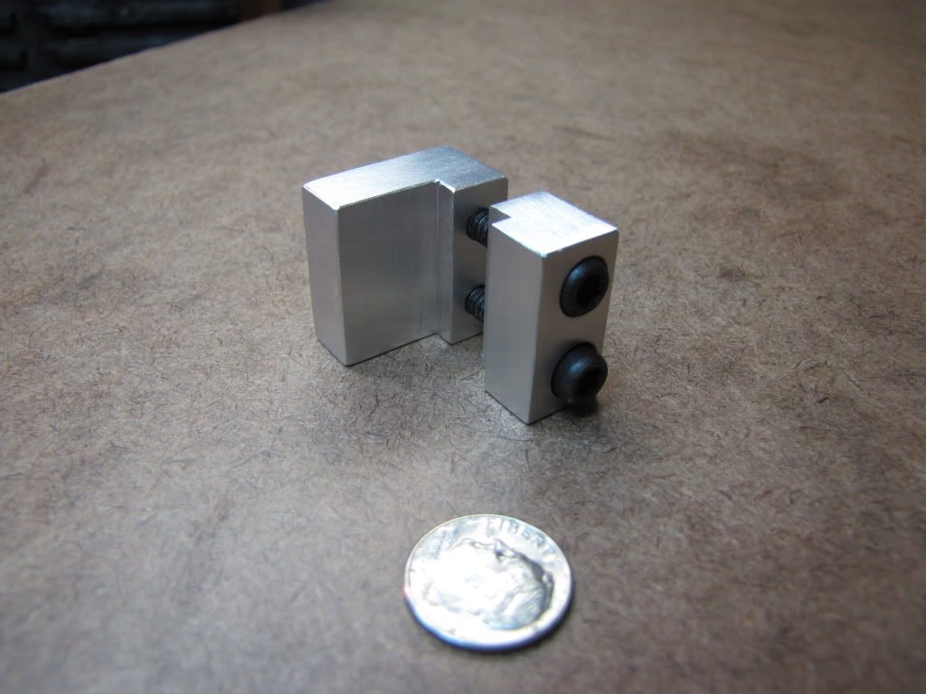
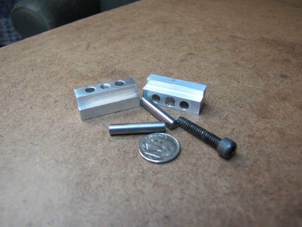
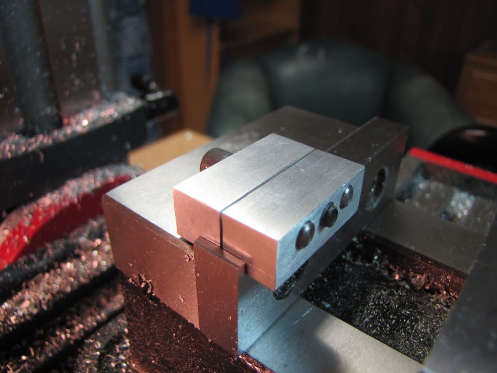
Drilled the holes. Threaded the two on the one. Countersunk the two on the other.

IMG_0265.jpg


IMG_0266.jpg


Was worried about the part going into the vise having a slight taper (0.005). Turns out that was the least of the problems.

IMG_0267.jpg


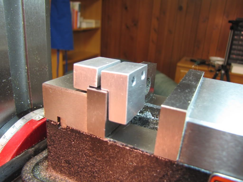
Tighten the screws and everything bows out.

I'm thinking the screws are going through too high off the vise. If they were closer then the top of the vise wouldn't act so much as a fulcrum.

Am I right in thinking the screws need to just 'lay' over the vise?

I think it's salvageable though. I can cut more off more parts the and bring the screws down.

Other notes...

1) Used 10-24 because that's what I've got. Word is to use 10-32.
2) Used aluminum for the blocks...should make steel or do something else about the screws (see Foozer's earlier post about studs-n-nuts.

At those angles there's not a lot holding the stop onto the vise...just the edges. I'll need to fix it.
 
zeeprogrammer said:
Not what I'd hoped for...

World of levers and as you found the fulcrum point, top edge of vise. I think this is where you drill and tap a hole into the side edge of the vise jaw.

Killing time, have the bike cylinder in the over so I can pull the sleeves out, Bride doesn't appreciate the smell of hydrocarbons as I do and is informing me of that to no end. Got to keep checking her chair and see if the egg has been dropped yet :) So thinking about your indicator blocks, drew another version. (paper engineer) Rather than a taper just cut a slot and mill down the side of the bolt to match. Slot keeps the bolt from turning, removable and what the heck, you have a mill. Sketch shows a 1/4-20 bolt, a 10/32 probably would be more suited.

(But Honey, thats the smell of progress coming from the oven)

block-a1.jpg
 
You left the pins out! - the ones that should have gone in the concentric holes drilled when the two parts were one piece of stock.

Look closely at the commercial version

http://www1.mscdirect.com/CGI/NNSRIT?PMPXNO=1802317&PMT4NO=66502174

The pins keep the two parts parallel while the screw draws them together. As you've discovered, the arrangement you have right now will never work - the parts will always try to pivot around the top edge of the vise jaw.
 
mklotz said:
You left the pins out! - the ones that should have gone in the concentric holes drilled when the two parts were one piece of stock.

The pins keep the two parts parallel while the screw draws them together. As you've discovered, the arrangement you have right now will never work - the parts will always try to pivot around the top edge of the vise jaw.

Well poo! (There's another one Vernon.) I was just coming on to have a partial celebration. I reworked the parts. I'll get to that in a moment.

I was going by the pic of the stop from 'Open Column etc.'. It looked like there were 3 screws. I guess there are two pins and 1 screw. Poo! I didn't know there was a commercial version. (What would I have done? Hm Marv? What would I have done?)

Well...I'll post this anyway...

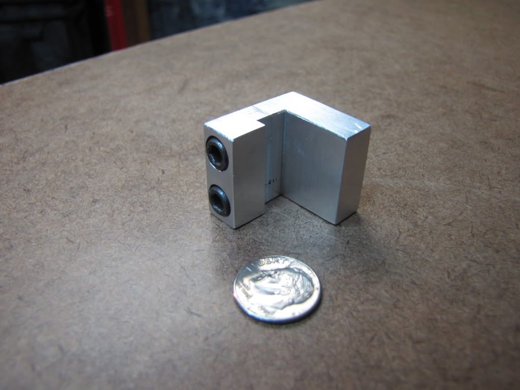
I took advantage of the two screws I had and treated the two pieces as one. Put it in the mill, cleaned up the edges, and milled to get the screws closer to the top of the vise.

IMG_0268.jpg


IMG_0269.jpg


Better? No?

One screw is better than two. (Don't no one go there.) Funny too...a little voice was trying to say something to me about that. Well...tinnitus and all that.

What holds the two pins in? If anything. Are they sitting in a blind hole on the 'back' part?

$16...are you kidding me!?

I'm going to get a screwdriver. You know the kind.
 
Cool idea Robert. I like it. Probably don't even need to machine the bolt head.

Don't think you meant to have a square end though. Just take the end mill in far enough.

I still need to find #10 hex bolts but I suspect the head is short enough that there's plenty of room. Can do both sides so you don't have to play 50/50.

If I wait long enough I'll find these things in my mailbox. :big:
 
zeeprogrammer said:
Cool idea Robert. I like it. Probably don't even need to machine the bolt head.

Don't think you meant to have a square end though. Just take the end mill in far enough.

OOPS, well me no engineer so :) changed it

I still need to find #10 hex bolts but I suspect the head is short enough that there's plenty of room. Can do both sides so you don't have to play 50/50.

Ought to have one in the barn, I'll measure and change pic, course then it'll require an odd sized end mill, Six of one, half dozen of another.

Looks like you have enough room in your clamps to get a pin between the bolts. Not enough room tho to place it above the bolts center line thereby shifting the fulcrum point from edge of vise jaw to the pin.

Robert
 
What I might/should've done is place the screws one on top of the other. Then it becomes more like a machinist's clamp. But what do I know.

One thing I don't know is how the pins help move the fulcrum point.
 
I was going by the pic of the stop from 'Open Column etc.'. It looked like there were 3 screws. I guess there are two pins and 1 screw. Poo! I didn't know there was a commercial version. (What would I have done? Hm Marv? What would I have done?)

That's the same MSC URL I put in the 'Open Column ...' thread (pg. 20 of the thread) so, if you read my post, you had the picture and the price back then.

$16...are you kidding me!?

Now you understand why we all make as much of our own tooling as we can. Actually, $16 is pretty cheap. At a $75/hr labor rate, that's 13 minutes of machinining and none of us can make that in 13 minutes.

The pins are fixed in the jaw that goes inside the vise gap - either by press fit or Loctite. They extend through close-fitting holes in the other jaw of the stop. The idea is that the two stop jaws always remain parallel as they move. Many vise-like items use this configuration, e.g....

http://www.micromark.com/HAND-VISE,7287.html

http://www.micromark.com/MINI-VISE-3and4-CAPACITY,7537.html

or, my soldering vises...

TWIN2.jpg


Have you tested your stop? Try tapping it with a small hammer and see if it moves. Remember, it's going to see vibratory forces if you machine a part that's pressed up against it. It needs to have a good grip on the vise jaw. If you can put a rod under it and pop it off with finger pressure, it needs rework.
 
mklotz said:
That's the same MSC URL I put in the 'Open Column ...' thread (pg. 20 of the thread) so, if you read my post, you had the picture and the price back then.

I did read it. Evidence of 'selective memory'. I certainly remember the machinist's clamp since that was one of my first projects. Glad though that I went back to review it...I took another look at your diagram of the 'woodworker' stop. I didn't understand it at the time...I do now.

mklotz said:
Now you understand why we all make as much of our own tooling as we can. Actually, $16 is pretty cheap. At a $75/hr labor rate, that's 13 minutes of machinining and none of us can make that in 13 minutes.

I though it was for fun...or to annoy newbies. :big:

mklotz said:
Have you tested your stop?

Yes. It's not going anywhere. Tried to lift it off with a rod. Tapped it with my mallet. So it works...but...

1) aluminum won't last as long
2) two screws takes more time than one...maybe other issues
3) what else?

Still...worthwhile. Learned a few things.
 
Couple other things-- your inside corners might not be completely square, depending on how you cut them and what your tool geometry was like. If it sits still then who cares. You'll make other stops someday anyway ;)

I'm also not sure you want all that depth on the in-jaw leg. It's going to make a nuisance of itself when you want to use parallels and the stop is far enough over the parallels can't sit on both reference surfaces of the vise.
 
shred said:
You'll make other stops someday anyway

I'm also not sure you want all that depth on the in-jaw leg. It's going to make a nuisance of itself when you want to use parallels and the stop is far enough over the parallels can't sit on both reference surfaces of the vise.

Which is why I'll probably be making more stops. Right now I'm looking to make the half joints and such to hold the indicator. I hadn't thought about other dimensions. If too long, I can shorten.

With my limited experience, I can't foresee what will be a problem, what will work, etc. So...gotta get the experience. Even when someone says 'do it this way' or 'that'...that's based on their experience and what they made. Good for guidance though.

Thanks.
 
Depth, nuthin', you won't want all that THICKNESS, either. suppose you're trying to stop a thin part, the movable jaw's gonna clamp on your stop before it clamps on your stock. If it were still relavant by tomorrow evening, I'd post a picture of one of my vise stops at work, a cheapy commercial stop, with one half milled thinner than .125".

 
zeeprogrammer said:
With my limited experience, I can't foresee what will be a problem, what will work, etc. So...gotta get the experience. Even when someone says 'do it this way' or 'that'...that's based on their experience and what they made. Good for guidance though.

Thanks.

As someone once wrote: "Good judgement comes from experience, Experience comes from bad judgement."

Dave
The Emerald Isle
 
Vernon said:
Depth, nuthin', you won't want all that THICKNESS, either. suppose you're trying to stop a thin part, the movable jaw's gonna clamp on your stop before it clamps on your stock. If it were still relavant by tomorrow evening, I'd post a picture of one of my vise stops at work, a cheapy commercial stop, with one half milled thinner than .125".

My initial intent is to work on the half joints for the indicator holders. They're 1/2" so I made the stop 3/8. When the time comes for thinner parts, I was thinking pusher blocks. Not that a thinner stop wouldn't work for the half joints.

Dave's post says it all (although I wished the writer had said 'poor' rather than 'bad').
 
2nd run at the stop. (That sounds odd.)

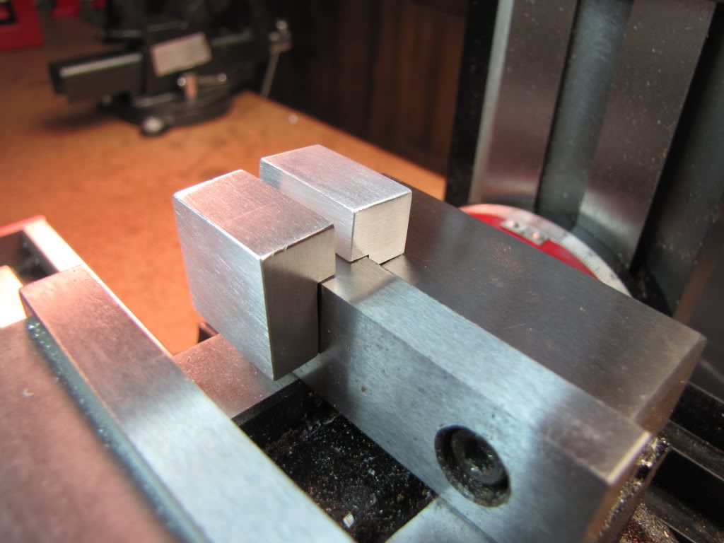
Making it a little smaller allowed me to use a 1" square piece of aluminum. Had a spare bandsaw blade (picking up a 'good', well better, bandsaw this weekend) so hacked off a chunk. Kept it as one piece (hopefully making a couple of people happier). Squared it and shaped it. Then drilled holes. Drilled two and reamed to 3/16" for some steel rod I had. Drilled the center to tap for a 10-24. Made pins out of some steel rod I had. Finished shaping (the channel). After cutting apart, drilled out the one hole to let the 10-34 pass through.

Looks okay...

IMG_0270.jpg


Fits/works better! Hopefully the 'couple of people' are happier. I know I am.

IMG_0271.jpg


So there it is. A stop. Hardly a 'woo hoo' but maybe a 'wee hee'.

Now I can get started on the indicator holder half joints that Foozer has been kind enough to design.
 
Back
Top