Ignition circuit help

Home Model Engine Machinist Forum

Help Support Home Model Engine Machinist Forum:

This site may earn a commission from merchant affiliate links, including eBay, Amazon, and others.
Mosey:

No problem here. I didn't interpret it as a "smatypants" remark.

If you mean he should bite the bullet and buy a new coil, as I understand it these coils are hard to find and the design of the engine (so far) requires this type of coil. I was wondering if maybe he could get someone who stocks the coils interested in what's he's doing enough to borrow a known good coil to try.
It's pretty simple like it is. I hope he can get it working.


Not sure if you're coming into this late but the engine is a little different arrangement than most. Ignore below if you know what's going on.

For the benefit of others:

Correct me if I'm wrong Steve:
The engine has no distributor (shaft or otherwise) - only a container that looks like one. Inside there is the circuit to drive the coil. The coil is a bit different in that it can fire both cylinders at once. The coil drive circuit is fired by a hall sensor and magnets. In order to use a conventional coil he'd have to add a distributor and drive shaft from the camshaft or use two coils and two circuits.

Sage
 
Modelman1838:

Brilliant idea. I think I have one of those on my barbeque. It has batteries right? I also have one of the other push buttton "snappy types".
Do you know how that electric one works?

I have seen engines using a mechanical piezo ignitor with a cam to snap the button like you would by hand. But not using the electric kind. Cool.

I'm wondering if it would have trouble with higher compression. Any idea what the compression is on your engine. I'm not familiar with that engine.

I'll have to remember that trick. Ignitions are always a pain.

Thanks

Sage
 
Les_s: thanks for your comment:)

Steve: I have two more sugestion for you
#1 would be to simply replace your coil with a led and a 470 ohm resistor in series and slowly turn your motor
by hand. this would tell you how long your charge time is. the led should be off only when the magnet is in front
of your hall sensor .
#2 this is the method "if in doubt use C4"Rof} use a variac and increase the input voltage and use a 120 volt house swithc
to control your pulse. In crease the voltage more and more and look what the outcome is. I know for a fack that some miniature coil
need 200 volt on the input to work could be you case

And if plan C doesn't work.... so what their is 23 other letter in the alphabet Thm:


#1 - Yeah I can try that. I might have some time this weekend to do some more testing.

#2 - Yeah I cant do that. I don't have the means or equipment to do that.
 
I might have already smoked the first coil, I didn't want to try the same thing and smoke the other one.
Istr all the Dodge Neon's used a pair of single coils with dual output. At the expense of remaking a bracket, you wont be sol if you need to go to another design.
 
#1 - Yeah I can try that. I might have some time this weekend to do some more testing.

#2 - Yeah I cant do that. I don't have the means or equipment to do that.
I have my whole house torn up looking for my variac right now. I had intended on making an induction heater as my next project when all this ignition stuff started to come up. Now the place is an unbelievable mess. :eek:
 
Steve, I'm totaly lost where does that 450 comes from. I must assume that your crank is like a V-TWIN motorcycle

BTW are you trigging that hall sensor with a south pole and with ground are you using to check your spark your primaty
or your case ground


It's a 90 degree v so it pops coasts 270 and pops again. Then the motor has to coast 450 degrees back to TDC #1.

270 + 450 = 720 degrees. two 360 degree rotations for a 4 stroker.

I trigger the hall sensor with what ever side makes it turn on and off. It isn't marked so I have no idea what pole that is.

I check the spark by putting one HV lead to the sparkplug cap and the other HV lead to the threads of the sparkplug.
 
Yes, good for a kilowatt or so. Make the inductance of the piston mistune a rf circuit and it oughtta spark on its own right. :cool:

Indeed, if Steve wants to make the trip, the offer is open.
If all goes well, version 2 of my CDI is only a few hours from working itself. Of course, two hours of "going well" can sometimes take weeks...


Thanks Jeff for the offer but I will wait until you feel you are ready. When you think it is the best it can be drop me a note and i'll bring the coil over and you can work your electronic magic on it.
 
I don't mean to butt in with smartypants comments, especially in an area where I know next to nothing, but what I do mean is to put a brake on the experimentation by using a conventional device. It's about the engine, and getting it to run. Unless Steve is happy putting in tons of time.
Mosey


Hey smartypants!! How you doing.

There are a couple things that keep me from going conventional. To go the distributor route I would need to make another camshaft because the current cam does not have a long enough tail to attach the rotor. I had to keep it short so it would clear the circuit board. I could make the parts and get it going. I guess I'm not ready to give up on this thing yet. If we get it running with the current setup it will be like no other and look real nice. I have 2 that run on the distributor. I guess I want something different. Who knows how many people this might help in the future. Everything you have ever seen on this site was an experiment at one time.

We'll get er Mosey. And don't worry about posting in a thread where you know next to nothing. I have been doing it all along!!
 
It's a 90 degree v so it pops coasts 270 and pops again. Then the motor has to coast 450 degrees back to TDC #1.

270 + 450 = 720 degrees. two 360 degree rotations for a 4 stroker.

I trigger the hall sensor with what ever side makes it turn on and off. It isn't marked so I have no idea what pole that is.

I check the spark by putting one HV lead to the sparkplug cap and the other HV lead to the threads of the sparkplug.

Thank for the explanation, now i get it
as for your ign sys your hall is a unipolar and it will only trigger with south pole
as I mentione before thats not realy a coil but a step up transformer to check your spark you have to go
with (of course) the HT output but the ground must be the laminated steel of your coil itself
 
#1 - Yeah I can try that. I might have some time this weekend to do some more testing.

#2 - Yeah I cant do that. I don't have the means or equipment to do that.

for #2 you can put 4 60 watt bulb in serie acting as a voltage devider you would have 30 60 90 120 volt ac output
 
Hi Steve,

I said I was bowing out but couldn't resist. Do you happen to have a part number for your coil or know what the original application was? (forgive me if it was posted earlier). I've been reading up on some of the wasted spark systems and it appears that most coils don't like to have either HT lead grounded which sounds like the method you were using to test with one spark plug. Also, it appears that some of the control modules that run these coils actually use a PCM signal which would make the coil act more like a transformer and produce multiple sparks per hit instead of a single spark each time one of the two plugs is supposed to fire. If I can get my hands on a coil the same or very similar to yours I'll pick one up and see if I can have my way with it.

Best Regards,
Les
 
Gentelmens we have a problem:hDe:

I waited a few days before posting this, I did duplicate all the versions that was offered
to Steve ALL of them are working with a regular coil, none with a waiste typeth_confused0052
my next step being a GM Grand Master Tech I have some small advantage.
I will have a new crank sensor ign module and coils to do all the testing I want to.
Dont try a variac I have a variable AC power supply and i was tripping 10 amp reset
cheers

I would not expect anything exotic for a reason, like the secondary center tapped to ground. Did you simulate the spark passing through a ground in common with the primary?
In automotive use, these coils are driven rather hard. So hard, that they crack and fail if the driver circuit is not functioning correctly. These are not like the old oil filled coils that can tolerate full voltage constantly.
While I am unhappy with the spark from my MKI version of my CDI, it does spark. :confused:
 
Hi Steve,

I said I was bowing out but couldn't resist. Do you happen to have a part number for your coil or know what the original application was? (forgive me if it was posted earlier). I've been reading up on some of the wasted spark systems and it appears that most coils don't like to have either HT lead grounded which sounds like the method you were using to test with one spark plug. Also, it appears that some of the control modules that run these coils actually use a PCM signal which would make the coil act more like a transformer and produce multiple sparks per hit instead of a single spark each time one of the two plugs is supposed to fire. If I can get my hands on a coil the same or very similar to yours I'll pick one up and see if I can have my way with it.

Best Regards,
Les

I don't have a part number or even a manufacturer. It was for a 90's snomobile or seadoo.

I did not ground either HV lead. Just simply connected one to the top and one to the threads of the sparkplug while it layed on a rag on the bench.
 
beeing a Grand Master Certification I can assure you that these areThis posting whent with more testing
than no one can think of. I should have a new module tomorrow with 3 other coils to check what is realy comming out
of those wires getting this coil to work.
it's going to need aaaalllooottt of power with my ac ps I was blowing 20 amp fuses :eek:
 
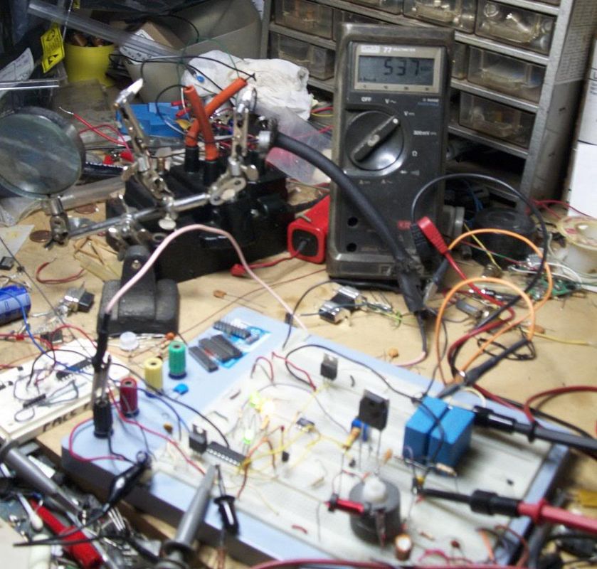
Pardon the messy bench.
bench.jpg

[ame]http://youtu.be/M3_7SiNVw08[/ame]

Yes thats 537 volts showing on the old Fluke. If it aint somehow dangerous it aint fun. :cool:
Not finished yet, few things still left to work out, but the first few pops always make you feel better.
 
Thanks Steve,
I misunderstood how you had your coil hooked up.

Luc, it will be interesting to see what you come up with for the GM coils.

Jeff, that is some serious looking breadboarding there! be careful :)
 
Lakc:

Messy ??

Looks like the place blew up :D

Looks like you're on your way.

Can you activate the circuit with a pulse generator (555) or I guess since you have the uP you could have it activate itself. :)

Sometimes (most often) things go bad fast when you generate a lot of sparks in a hurry. RFI EMI power supply failure....

It's really satisfying to hear (and see) the circuit generate sparks at engine frequencies. (he says biting his tongue )


Sage
 

Latest posts

Back
Top