How do you machine such fine details please?

Home Model Engine Machinist Forum

Help Support Home Model Engine Machinist Forum:

This site may earn a commission from merchant affiliate links, including eBay, Amazon, and others.

hobby

Project of the Month Winner!!!
Project of the Month Winner
Joined
Dec 5, 2009
Messages
510
Reaction score
47
Ok,
You people are making these incredible, machining features.

I look at your models, and see the round raised areas around bolt flanges, and raised areas with curves and such, now when I look at that, I'm thinking rotary table, and x,y, axis movements on the mill table, that's alot of different table and rotary moves to keep track with, so is this the method for making these features, or can these be done without a rotary table, and use files and grinders an things?

Can someone please explain in basic details, how you guys accomplish these features,

it is almost like trying to figure out how a magic trick was done, you think of the most impossible means of doing that trick, but when it is revealed how its done, you realize, WOW, that wasn't so hard to do, once you know there secret of how they do it.

So could you machining magicians, reveal some of your secrets to the rest of us, so we can do the same tricks....

Excellent job all you guys and gals, who do the superb model engineering projects on this board.

Have a great day...

 
Can't speak for how others do the raised area around bolts but before I had a rotary table I did it with a file.
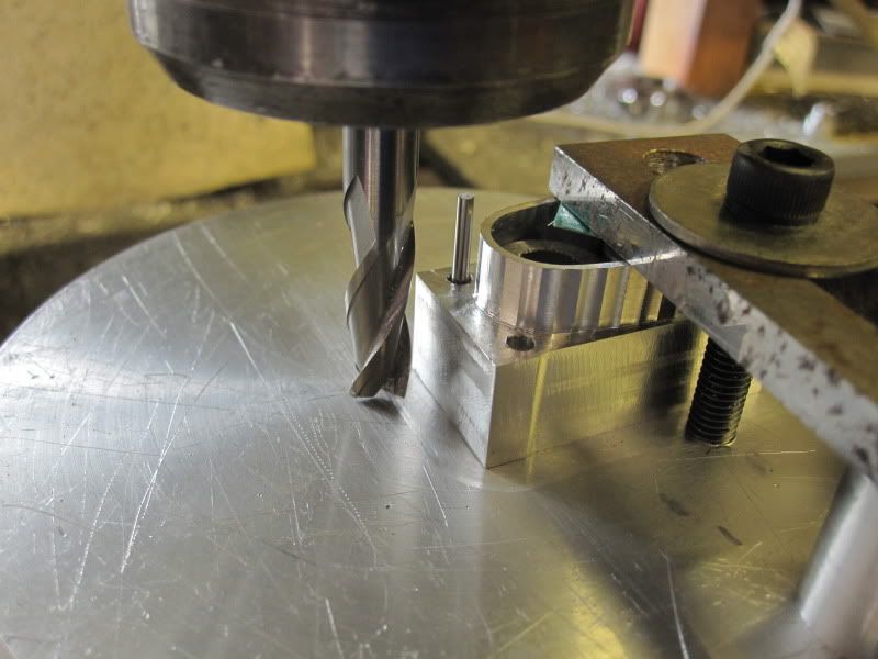
When I got a rotary table I used this method. First center the rotary table under the mill spindle. Then the item with the bolt hole centered under the spindle. Then move the table over the desired amount and mill the raised area.
For this type of work where a couple of thousands make no difference I use a arbor that has my rotary tables MT on one end and other end is turned to a 1/2 inch. I mount the 1/2 inch in a holder in the mill. Then mount the rotary table on the mill table but level the bolts lose. Lower the quill and let the MT move the rotary table until it is centered under the spindle and then tighten down the bolts. Then mount a piece of drill rod the same size as the bolt hole in the mill and use it to center the part to be milled and clamp it down. Then all you have to do is mount the milling cutter and move the table and make chips.

 
Another method if the part is going to be painted is to drill a shallow counterbore to the hole then turn up a short length of rod to fit the counterbore and drilled the same clearance size. This can then be soldered or even bonded into the counterbore and a fillet of solder or epoxy added around it to get that cast look.

Don't have any close up pics of one that I have done but take a look at Ramon's base for his table engine which uses that method.

http://www.homemodelenginemachinist.com/index.php?topic=16453.0

As you say the other method is RT or if its a shaped boss then plenty of hand wheel twiddling and file/die grinder. Have a look at my IHC cylinder head in this post.

J
 
Thankyou guys

For taking the time to reply,
and the good learning procedures you guys gave.


It sounds like what was described in the OT is a casting boss, or whatever it is called... a portion of a casting that will ultimately see a bolt installed. The pattern maker creates this raised area, and it is cast in place, to be subsequently machined flat & true in a simple procedure. Without the spot facing for the bolt, tightening a bolt firmly can cause stress fractures or cracking.

You can do a negative "spot face" with ease by using a counter bore tool or end mill, and entering the metal only far enough to create a shallow, flat, circular area. While this is depressed and not raised, it still looks nice IMO and gives a machined part a cast look.

With a bit of experience, you will be able to identify parts that are cast, and those that are machined. Some casting-shapes would be enormously difficult to machine from solid, thus obviously, they are cast to begin with. Think cast iron engine block. It could be machined from a solid CI chunk, but there'd be massive waste and probably 10X the time and cost.

Some very advanced modelers can give something machined from solid the appearance that it was cast. They are the true magicians!
 
Hobby,
Depending on what type of boss or round shape you want to machine there are several different ways of attacking it.
As has been mentioned you can use a trusty old file.
Next up would be a rotary table. With this method you need some way of locating the boss or round shape at the center of your table so you can 'spin' the shape. With a number of bosses to do it could take awhile moving, locating and cutting.
Another method for certain types of bosses, the ones that are created around a drilled hole you can insert a small post with a shouldered area into the hole and grind a file to match the post diameter.
Last but not least is the mathematical sine/cosine method. With this method the radius of the boss and the radius of the cutter to be used are combined to create an arc. A number of steps are then developed around the curve so that you can step over so far in one direction and in, in the other direction. I use this method a lot as it saves the constant setting up to do it on a rotary table. Once the cuts are completed you are left with small steps that need to be ground and filed smooth.
A good example is this picture of my V-twin crankcase. You can see many different curved shapes that were competed by all of the above methods.
Pick your poison.
gbritnell

v twin crankcase.jpg
 
Swede,
Thankyou, appreciate the time you took to explain this better to me.

Gbrittnel,
yes, that is what I'm kind of trying to figure out how you guys do those kind of features.

A RT is good for some curved or hole work, but just because a curvature needs to be machined doesn't always warrant an RT, but rather working the cutter up to the facet, and then handwork to shape it up.

In my woodworking, I use pattern cutting router bits to follow shapes to be machined on a workpiece against a template guide, so by using the sine/cosine method and machining in steps, would be close to pattern routing, only the controle would be in the table movements, rather than handheld.

So a majority of roughing out a facet of some sort, could be done entirely with the machining in steps method, which would allow to move from one facet to another without RT set ups all the time.

I use my RT a lot for precise round facets to be machined, but for some curvatures it may be more productive to machine it in steps.

Thanks guys for your inputs.
Greatly appreciated.
 
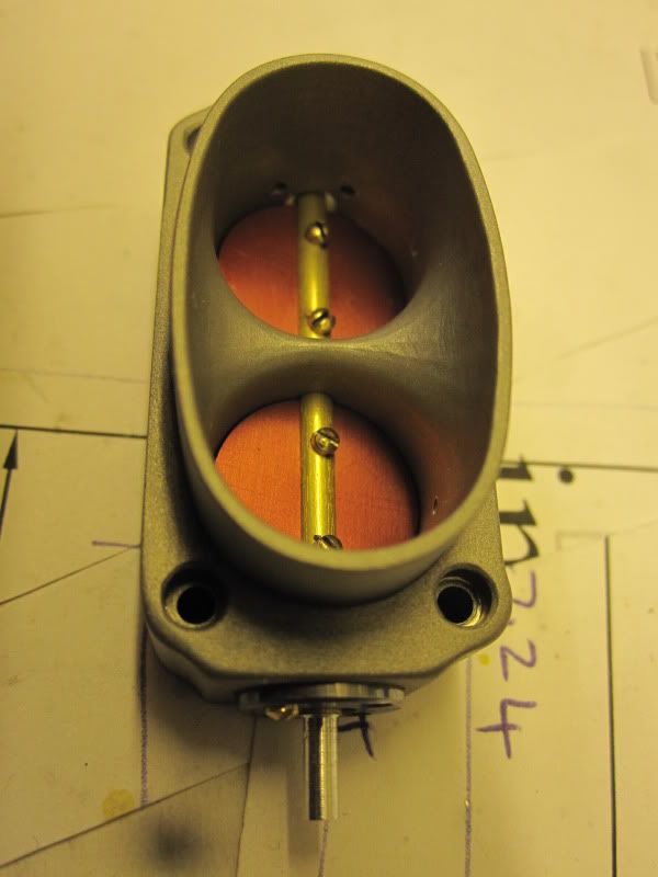
Hobby, just dug this pic up, from when I machined the ellipse on the front of my throttle body.
It shows the individual cuts made using George's last method in his post.
Unfortunately, without CNC there's no easy way to generate these type of shapes. You just chobble away what you can on the mill, and then it's out with the files and grinders, etc.

You really need to have access to some sort of cad system to dimension all the x,y co-ordinates.
This particular ellipse has maybe 60 or so separate cuts.
Cheers.
 
Sorry, forgot the pic

002-2.jpg
 
While I think, the inside of the throttle body was done in a similar way, but the depth of cut varied too,so on the cad you're plotting x,y and z. Maybe leave the z axis till you've played with the x & y?

011-1.jpg
 
If you have a CAD package you should be able to print out a set of X&Y co-ordinates to allow manual CNC by entering the cutter dia and steps eg for every 10thou on the x axis it will give you the Y value.

See the second pic here

J
 
If you're interested in seeing how this is done on the lathe, download my PROFILE program and run the default case that is included in the archive. It draws a picture showing the position of the lathe tool for each incremental cut.

The program includes a number of tools, such as splines, that allow the user to specify the shape he desires whereupon the program produces a file of the incremental cuts to be carried to the workshop.

If you're running a 64 bit system, you may need to run the program under DosBox.
 
Gentleman,
Thankyou very much, all your replies are very helpful, in getting a better understanding of how to take this hobby to the next step.

Kieth your build thread is what got me started asking these questions,
the picture you presented is very helpful to look at and studey your procedures.
As well as the explanations given.

I have manual machines, and I do have a CAD program, (turbo-cad), that I use a lot for getting precise measurements for fitting parts before there machined.
I will start using it for calculating table movements as was mentioned, also.

Jason,
Thankyou for that link, I will look at that further to learn more about these procedures, also thanks for the tip of using my CAD as a manual DRO, to calculate the "x,y,z" coordinates.
Very helpful.

Marv,
Thanks for the reference to your profile program,
That looks very interesting to see the incremental cuts involved in doing profile work on a workpiece.


While were talking about using CAD,
Here is a quick tip, for using CAD to design a project from scratch, if your not already doing this,,,

Draw up your own hardware store,
draw up to acttual size the most frequently used hardware you use for your projects (screws, nuts, washers, tubings ect...) These can be archived, even some of the most frequently used size drill bits, as well as a simple 2D model of your RT, and other fixtures, to know how to place your workpieces on them for best fit...

Then when you design your parts you could place these in the drawing as needed to check for proper clearances, and with the hardware, it will allow you to determine what size fastener will best fit on your workpieces.

Thanks everyone for your inputs.
Greatly appreciated...


Latest posts

Back
Top