Horizontal Single

Home Model Engine Machinist Forum

Help Support Home Model Engine Machinist Forum:

This site may earn a commission from merchant affiliate links, including eBay, Amazon, and others.
If anyone is having problems reading the drawings, left click on the image and pick Properties. This will give you the link to Photobucket where you can see the full size drawing.

Thx...
Chuck
 
bearingcaps.png
 
I think I'm about through with the drawings unless anyone needs details on something I haven't done so far. Let me know.

Chuck
 
cfellows said:
I think I'm about through with the drawings unless anyone needs details on something I haven't done so far. Let me know.

Chuck

I believe we are going to build this as our next team build. So as long as it is OK with you, be prepared to answer questions about it. ;D

Eric
 
Happy to answer questions. Also happy to provide any other drawings if members have questions or are vague on anything...

Chuck
 
Chuck,

Do you have anything on the cam and follower/keeper/fork rod item?

Thanks, Bret
 
I've just been browsing through the drawings and was about to ask a similar question :D, cheers Bret

Chuck, thanks for taking the time to post all the drawings and photos, it's really informative, however at present I'm struggling to grasp the workings of the cam and timing mechanism etc, I believe I'm OK with the principle ..... "a la' IC engine" ...... inlet opens briefly, a nad's after TDC following the exhaust stroke to produce the next revolution, then exhaust stroke again and the mass of the flywheel keeps the whole thing spinning (please forgive the complete idiot's explanation) ....... I'm just not quite visualising the actual "nuts and bolts" of it ;) ............ sorry about all the questions btw.

It's a great looking (and sounding) engine 8) and I'm determined to have a go at one in the future, but, as a complete novice I think I'd better start with something simple ???

CC
 
bretk said:
Chuck,

Do you have anything on the cam and follower/keeper/fork rod item?

Thanks, Bret

Bret,

I'll try to post some drawings / pictures this evening. The cam arrangement isn't the best and I've been thinking about some way to improve it. What kind of gears did you get (pitch and number of teeth)?

Chuck
 
CrewCab said:
however at present I'm struggling to grasp the workings of the cam and timing mechanism etc, I believe I'm OK with the principle ..... "a la' IC engine" ...... inlet opens briefly, a nad's after TDC following the exhaust stroke to produce the next revolution, then exhaust stroke again and the mass of the flywheel keeps the whole thing spinning (please forgive the complete idiot's explanation) ....... I'm just not quite visualising the actual "nuts and bolts" of it ;) ............ sorry about all the questions btw.

It's a great looking (and sounding) engine 8) and I'm determined to have a go at one in the future, but, as a complete novice I think I'd better start with something simple ???

CC

No problem on the questions, ask as many as you'd like.

The cam gears and timing are set up so the engine will run and sound like a four stroke IC engine, "firing" every other revolution. When the piston passes top dead center on the firing stroke, the cam opens the air inlet poppet valve. The incoming high pressure air pushes a sliding piston valve in the head to one side, closing off the exhaust port and letting the high pressure air into the cylinder. Just before bottom dead center, the air inlet valve closes, shutting off the high pressure air. A spring returns the sliding piston valve in the head to the other side, opening up the cylinder to the exhaust port. The engine then exhausts the compressed air. As long as the air inlet valve, which is driven by the cam, stays closed, the engine will be in exhaust mode and will freewheel as long as the flywheel keeps it going.

Here is the engine in freewheeling, exhaust mode:

AirValve1.png


And here as the cam begins to open the inlet valve. At this point, the sliding piston valve is in motion, sliding to the right:

AirValve002.png


Finally, here the air inlet valve is fully open and the sliding piston valve is pushed fully to the right, completely closing off the exhaust port:

AirValve003.png


Chuck,

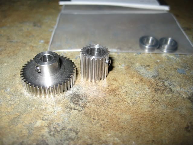
Gears are stainless steel, from you suggested supplier. 20 teeth on the pinon and 40 on the cam gear. 3/16 shaft on the cam gear. 48 diametrical pitch 20 degree pressure angle.

I am thinking of using the setscrew hole as my cam lobe by locktiting and bottoming a screw and rounding over the head to give a rough cam shape, what do you think?

pic002.jpg


-Bret
 
bretk said:
Chuck,

I am thinking of using the setscrew hole as my cam lobe by locktiting and bottoming a screw and rounding over the head to give a rough cam shape, what do you think?

-Bret

That's a good idea. The push rod has a roller that rides on the cam so any uneveness in the cam surface probably wouldn't hurt anything. You only need about 1/16" of lift on the cam.

Chuck
 
You could also make up a cam that slides on the hub with a hole in the low side opposite the lobe for access to the set screw. The you could still have a functional set screw so you could remove or adjust the gear. The cam could be very simple with straight sides to give a very fast lift and be Loctited to the hub.
Gail
 
Gail,

Actually the intermediate gear freewheels on the shaft so the setscrew hole is superfluous anyhow. This way I put it to some good use ;)

-Bret
 
Right you are Bret. I should think before I type.
BTW, I think I am OK on springs. Thanks for the offer in another thread. Just for interest, let me what sizes you are using when you have time.
Gail
 
Gail,

Springs are: OD .218, Wire .018, Length 1.75
and OD .218, Wire .023, Length 1.75

Finished a built up crank today, will be putting a .25 ID by .375 OD roller bearing in the large end of the con rod.


-Bret
 
Here are some pictures of the push rod assembly. This one was built up from a previous set up so it's probably not the way I'd build it again. The brass part is connected to the aluminum part with a 2-56 threaded rod so it's length can be adjusted. Also, the valve end of the brass piece is counter bored so it fits over the valve stem. The forked end of the push rod fits over the cam gear axle which has a head on it.

IMGP1036.jpg


IMGP1037.jpg


IMGP1038.jpg


IMGP1039.jpg
 
I have just about completed a better set of drawings for my horizontal single compressed air engine and should have the PDF file uploaded in the next day or two. It doesn't include Superfast's excellent hit n miss governor, but perhaps he will have drawings for that soon.

Chuck
 
I had a feeling that you was about to do this, GREAT! :bow: I've been gathering up materials, tools and parts and pieces in anticipation.
Thanks in advance.
Mel
 

Latest posts

Back
Top