Homemade DRO...maybe...sort of...

Home Model Engine Machinist Forum

Help Support Home Model Engine Machinist Forum:

This site may earn a commission from merchant affiliate links, including eBay, Amazon, and others.
Thanks Ron.

1hand...you're right about that author. That thread attracted some excellent repliers too.

Thanks Chuck. Actually no...I was surprised how easy it was with the dremel. Well...the angle grinder too. Remember...I have no experience with an angle grinder and precious little with a dremel (I had an old one for year). I think heat control was a lot easier with the dremel but that might be because it was smaller and by that time I was looking for it.

 
Carl,

Sorry I confused you somewhat.

When I said twist, it should have read tailstock ram rotation.

Even a very small amount of that rotation transferred to the rigidly mounted digi head could twist and distort it out of working.

What I suggested was going to the model shop and purchasing a couple of control arm ball ends and joining them together with a little threaded rod, as shown in the pic below.

Even though you will get microscopic out of alignment reading as the ram turns, I doubt it would even show up on your scale.

I did do a very fancy setup for the glass scale version on my lathe, but again, I had to come up with a slip joint that would compensate for ram rotation. You never know, you might eventually, one day, need to mount a glass scale to your tailstock.

http://madmodder.net/index.php?topic=1938.0

I hope it is now clearer.

Blogs


balljoint.jpg
 
Zee,

Have you looked at the DRO section on the CDCO tools website? They have displays for the scales and calipers. They also have photos of the glass scale DRO units.

Building a DRO system does look like fun, but buying the built parts, programmed, might be easier - leaving time to build engines!
 
To compliment this article, which is about drilling to accurate depths, I thought I would let you know about a little proggy in Marv's collection, that makes drilling holes more accurately to depth much simpler, by calculating how much extra depth you should add to take into account for the angled drill bit tip.

It is called DALLOW.ZIP. Which I used regularly until I recently converted over to a 64 bit machine, and now it refuses to run. But we can't expect Marv to cater for all eventualities. But it is well worth downloading and using if you use a 32 bit machine.

http://www.myvirtualnetwork.com/mklotz/#shop

I've now got to go back to pencil and paper


Blogs
 
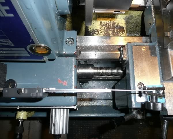
Here's my contribution
DSC02732.jpg
It enables me to take it of easily when not wanted,works well.
Don
 
Thm:
Nice Idea Don.
That just led to thinking about using a switchable magnetic base to hold the scale and a magnet on the end of the scale arm to attach to the carriage.
Quick, easy and removable.

Picture when the temp in the shed drops below 45°C

Cheers,
Phil
 
The trouble with that Phil is that it would be inclined to move when you least expect it,I wanted to drill a hole in the end for an allen screw,but couldn't drill the scale,didnt have a stellite drill.
Don
 
8:30pm now and 28deg C

The trouble with that Phil is that it would be inclined to move when you least expect it

You were spot on Don, I tried some 5x5x20mm rare earth magnets and they did allow the scale to shift.
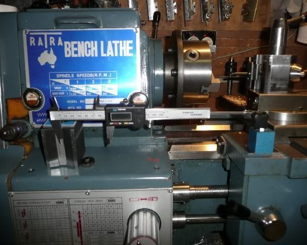
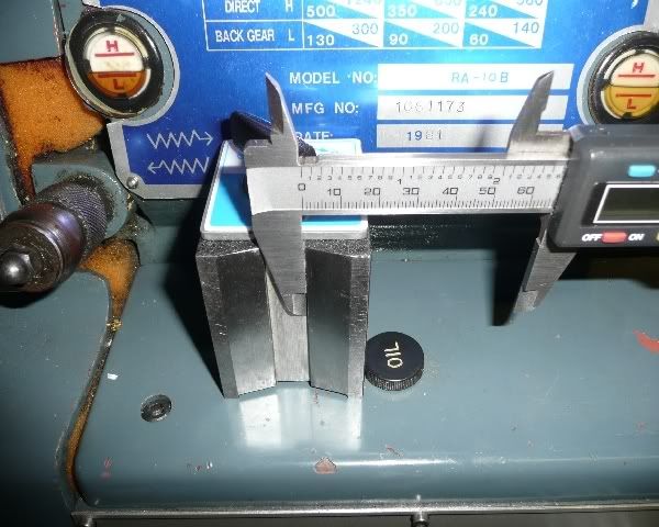
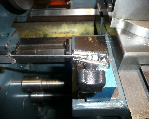
I was able to get around that problem by the method in the pictures.

image001.jpg

The grove in the DI base holds well and the other end is pinched in the cheap DTI base.

image002.jpg


image003.jpg


image004.jpg

It's not intended to be a fixed solution and only gives a longer range than my 30mm DI all be it one less decimal place in accuracy.

Sorry for the side track Zee, and thanks for the DRO350 info. I'll be onto that soon.

Cheers
Phil
 
Thats crafty Phil.Put a drop of oil in that headstock please. ;D
don
 
I don't sleep well in the first place...but last night was terrible. At first, every time I woke up, I was thinking..."Oh. That's what Blogs meant.". Then I started worrying that I hacked off too much...how am I going to mount it? Ah well.

Thanks Blogs. And thanks for the pics. To the hobby shop! ;D Also thanks for the link to Marv's programs.

ke7hr...thanks. Assembly shouldn't take very long. The enclosures and cables might be a different story. As for programming...the biggest hurdle will be acquiring the data stream but I have some source code to help.

Great contribution Don. Thank you.

No worries Phil. That's also a great contribution.

Before any one says it...mounting should have been addressed before hacking...ah well. But hey...cheap caliper...cheap lesson.

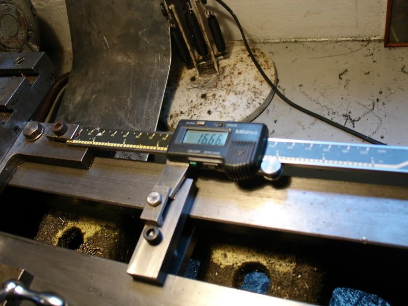
So...mounting the caliper. That's going to take some thought. I think the existing holes used to mount the display to the caliper won't work. The holes to be drilled and tapped in the tailstock just seem too small. They're on the order of 1/16.


zeeprogrammer said:
As for programming...the biggest hurdle will be acquiring the data stream but I have some source code to help.

Zee; Are you using the DRO350 or your own solution?
 
black85vette said:
Zee; Are you using the DRO350 or your own solution?

The only thing I'm planning on doing at this point is to display the relative position of an axis.

Converting the signal to position looks pretty easy. I'm going to use the PCB of a DRO350 to hold the electronics...but the only electronics from the DRO350 I intend to use are the 7-segment displays, their drivers, and the analog switches and op-amps for the signals from the calipers. I won't be using the PIC and therefore not its software. However, I think I have the software and can look at it for reference if needed. I won't be installing all the buttons. I can do that later should it become desirable. I just want power, mm/inch, and zero.

As for a processor...I haven't really looked but it's also straight forward...just some GPIO. I've seen some applications where a UART is used but it's not strictly necessary. The signals can be bit-banged. Because of my work I have a number of options from old evaluation boards. A Cypress PSoC, a TI 470, and an ST STM32 Coretex.

I'm favoring the ST simply because it's the processor I'm currently on at work. The other reason is that it supports USB. While my box computer supports RS232, my laptop does not.

One other thing I did was to order an LED/phototransistor pair (reflective). With that, and the same board, I intend to put together a tachometer for the spindles...and maybe an engine. ;D
 
Zee this is my version of a DRO this is on a myford lathe i only use it on final cuts only, where some accuracy is needed it fits on the tailstock and also the saddle, using the same modified caliper it fits onto the lathe very easily and is a handy mod
I drilled the caliper with a stellite? drill and as Marv i think suggested, take the battery after use to prolong it's life been using this set-up for about a year now with no problems at all, well worth doing

Max....

IMG_0107.JPG


IMG_0110.JPG
 
zeeprogrammer said:
how am I going to mount it? Ah well.

The way I mounted mine was gluing with epoxy a 5 mm piece of aluminium bar with a threaded hole on the back of the body, taking care not to cover the tiny screws on the calliper's back. In the front of the scale I milled a slotted 4x8 mm hole to aid in the alignment, but my calliper was made of plastic.

If you sharpen a "good quality" concrete drill, you can drill a hole in the calliper's tip.
Once I was able to drill out a 12mm broken tap from a cylinder head with a properly sharpened concrete drill.
 
Thanks Max and Helder.

One possibility I'm considering is to make a plate that will mount to the tailstock and then mount the caliper's slidey part to the plate.

In any case...the lesson here (I'm so terrible at lessons) is not to modify anything until you have to. In my case I started hacking before I had figured out the complete solution. But gee...it was my first time and I got carried away. ;D

 
zeeprogrammer said:
In my case I started hacking before I had figured out the complete solution. But gee...it was my first time and I got carried away. ;D

That's NOT how you're supposed to do it? ???

;D I've just always assumed that was how everybody's 'stuff' got done 8) Figure out most of what you're doing and what you want as a result. Then close your eyes. Wade in. Start swinging. Try not to bleed on it. Cuss alot if you want it done quicker. And smile when you're done. If that doesn't work. Rethink it. Then do it the same way at least one more time before changing :p


Hard headed and consistent,
Kermit
 
Ah...thanks Kermit. I really wanted to hear that. Seriously...helps a lot. ;D

 
Ahhh, Zee, if I were a girl I'd be weak in the knees from all your talk of GPIO, UART's, and bit banging! :) Seriously, wish I had half of your knowledge of digital electronics.

Chuck
 
I agree with Kermit, and if all else fails, form a committe to study the problem. More than once the committe has been made up of Me, Myself and I to sit around and drink coffee and study the problem.

JimN
 

Latest posts

Back
Top