Gearless hit and miss engine of my own design

Home Model Engine Machinist Forum

Help Support Home Model Engine Machinist Forum:

This site may earn a commission from merchant affiliate links, including eBay, Amazon, and others.

Chicken

Active Member
Joined
Dec 27, 2012
Messages
41
Reaction score
52
Hi!

Today I fired up my new gearless hit and miss engine for the first time and to my surprise it startet and ran very well right from the beginning!
I aquired some cast iron parts, the rest is entirely my own design.

gussteile.jpg


It's running using a petrol vapour carburetor similar to the design of Jan Ridders, just scaled it up a bit so it suits for this engine.
It has a 46 mm bore and a 60 mm stroke which makes 100 cm³
The Flywheel is almost 30 cm in diameter and weights 10 kg.

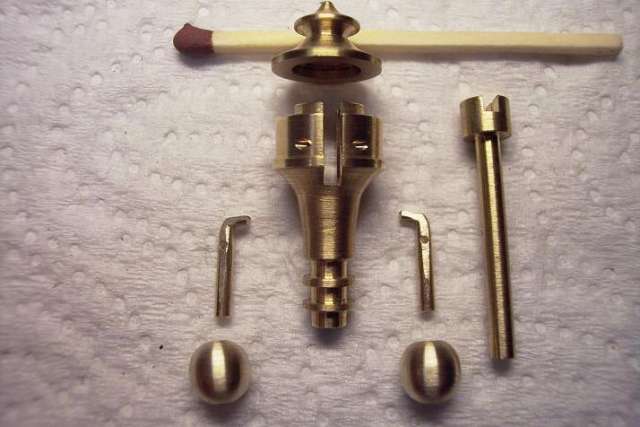
I've built a small belt driven fly ball governor which controls the speed.
As it is the first run and some things are still a little tight, it is still fireing quite often, but I think after some tuning it should have more miss cycles.

Here is a short video of the first run! I don't have a water pump yet so I had to stop it after about 5 Minutes as it was getting warm.


[ame]http://www.youtube.com/watch?v=qfHVVReyi1U[/ame]

I hope you like it!

Best regards,
Alex
 
Very nice indeed. Congrats on a great first run. Just curious, did you design with CAD or figure out all those bits on paper? Someday, I wish to do that.

Anyway, once again, very nice.

--Mark
 
Nice looking engine, runs good too. That's quite a quite a horse, with almost a 2" bore.

Chuck
 
Thank you very much for your nice comments. Unfortunately I don't have any plans, just a few rough scribblings on paper for some critical parts like the timing wheel for the valve mechanism where I used my indexing table.
The rest basically was built just right out of my head without really thinking about it. Of course sometimes I ran into trouble as I did not think far enough :p
For example I was planning to raise the exhaust straight up, but then it would collide with the fly-ball governor, so I had to add another 90 ° bow and some other similar things. But in the end it all worked out somehow.
I built the valve control according to this video:
[ame]http://www.youtube.com/watch?v=DXklWMClxrM[/ame]

As I didn't have any plans it's my own design. I also use a different indexing than shown in the video. My timing wheel has 4 bumps and 4 grooves, so I have to turn the timing wheel by 45° during each stroke of the eccentric.
The exhaust valve has a stroke of 8 mm, so I thought the eccentric stroke must be double this value. This opens and closes the valve within half a turn of the engine. I decided to use 15 mm stroke of the eccentric so the exhaust valve opens just before bottom dead center and closes just after top dead center. It turned out to work very well. The excessive stroke of 7 mm is used to turn the timing wheel when the valve eccentric is close to its bottom dead center.

The fly ball governor was built by looking at the picture from Find Hansen:
regulator%203.jpg-for-web-LARGE.jpg


My governor is basically the same design, of course much larger to fit my engine. It just catches the exhaust valve push rod and holds the valve open. Very simple actually.

Best regards,
Alex
 
Congratulations on a great job.
The sound was great and took me back many years to when I heard full size engines working.
 
I like this! Nice work. I like the idea of a gear less engine and may have to try to build one also.

Thanks for showing this.
 
Hi!

Thank you for your nice comments!
After about 2 hours of running now the engine turns with even less friction and is missing even more strokes now. It turned out that this is the most economical engine I have in my collection. It will run more than 20 minutes with only 10 mL of fuel :)
When running without load no cooling is required anymore.
Still I need a small water pump for periods of higher load.
I want to build a pump as compact as possible. Has someone ever built a small rotary vane pump? I think this should be the most compact pump possible?

best regards,
Alex
 
Hi!

As mentioned before, this engine is built mainly straight out of my head. I don't have any plans, just a few rough scribblings for some critical parts like the timing wheel for the gearless valve control.

This for example looks like this:
skizze.jpg


After machining it looked like this:

steuerrad.jpg


For most other parts, I did not create any scribblings and just started building.
The cylinder also is not made from one part, it's made from two steel tubes and two steel rings on each side and then glued together with loctite super strength

The valves and valve cages were made from bronze. The valve head was silver soldered onto a drill rod bar. which looks like this in detail:
ventil.jpg


The connecting rod was also made from several parts and bolted together. For the crankshaft side, I used a massive cast iron bearing. This works surprisingly well without any wear.

pleuelstange.jpg


As an ignition source, I use a "Blokker" type ignition as described by Jan Ridders, just modified it a bit so I don't need a reed switch or so, I just have a simple contact on the crankshaft and I use the engine mass as second contact.
I put the ignition into a small wooden box:

zuendung.jpg


So I'm sorry that I can't supply detailed plans as I don't have any. But of course I can answer any questions about dimensions and also supply many detailed images if one is interested.
As I'm from Germany, all dimensions are metric!

Best regards,
Alex
 

Latest posts

Back
Top