Gear pump

Home Model Engine Machinist Forum

Help Support Home Model Engine Machinist Forum:

This site may earn a commission from merchant affiliate links, including eBay, Amazon, and others.

Brian Rupnow

Design Engineer
Project of the Month Winner
Joined
May 23, 2008
Messages
15,250
Reaction score
8,532
Location
Barrie, Ontario, Canada
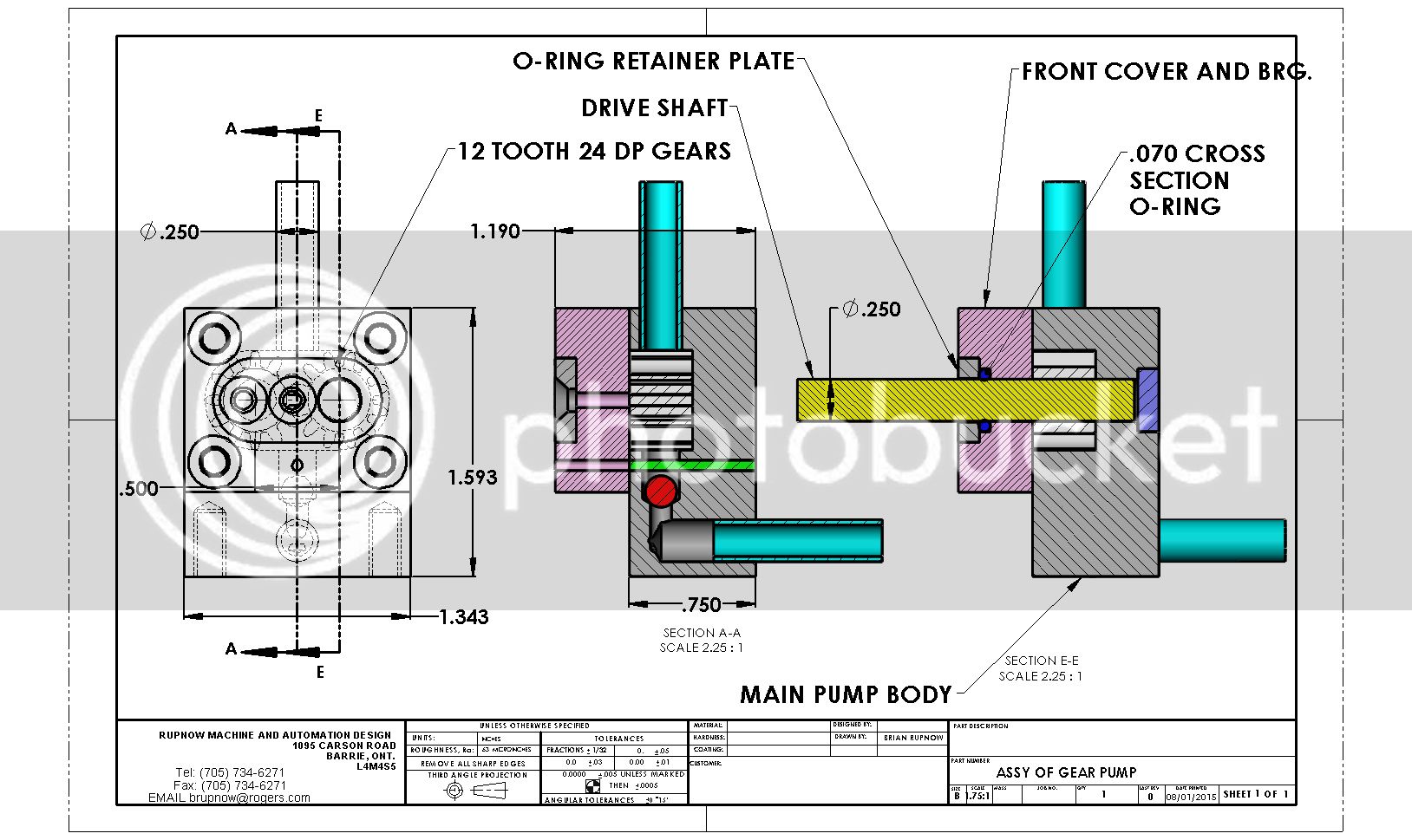
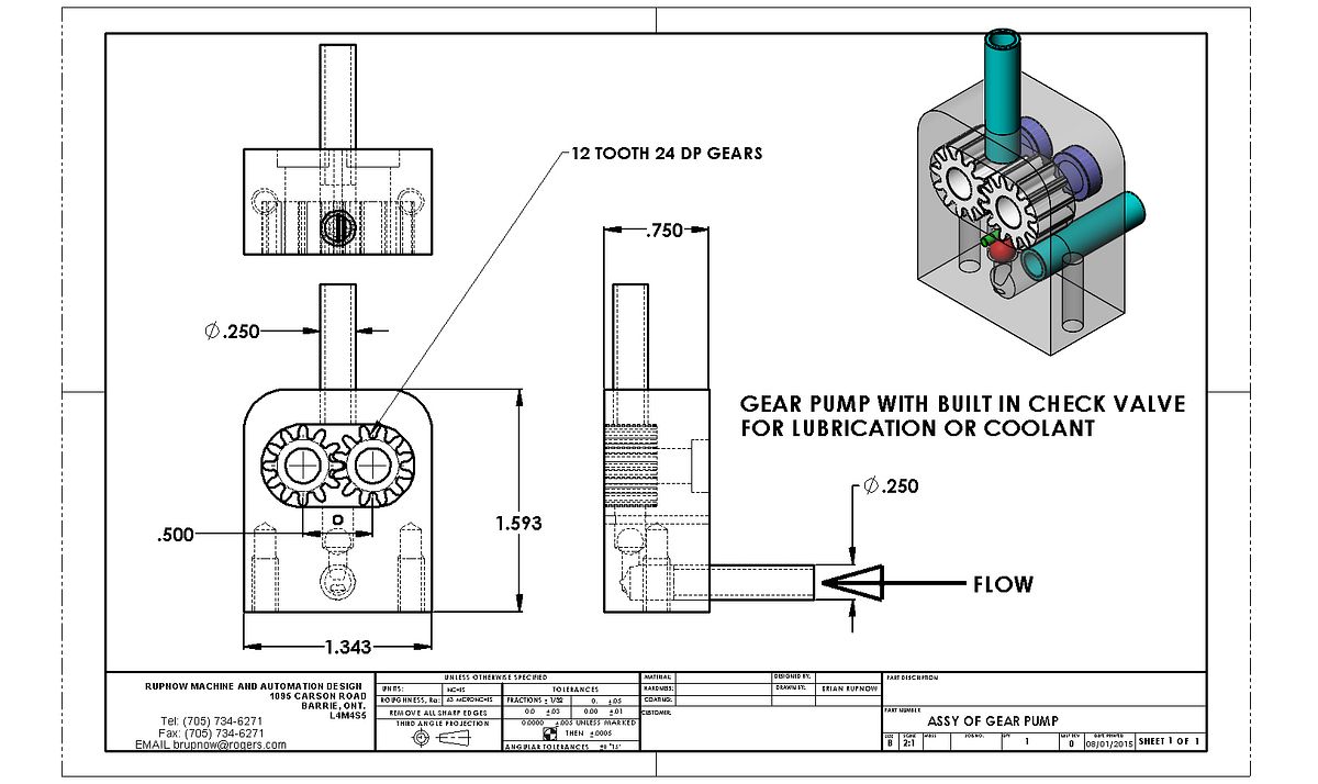
I may build a gear pump, just for interest sake. I finally bought the last cutter for my 24 DP gear set which will let me cut 12 and 13 tooth gears, and I have never built a gear pump before. The drawing isn't finished yet, so don't shoot me. I haven't put the shafts in, nor the near side cover, but I will get to it. If you are interested, then follow along.---Brian
 
Looking forward to this project. I've been wanting to build one for some time now.
 
The only difficulty I foresee is end clearance between the end of the gears and the inside of the housing. I have some "real work" thanks to my new Solidworks installation, but I still need a "play project". It may be quite a stunt. If the gears are too long, the cover won't bolt on tightly enough and fluid will leak out the joint between the main pump body and the cover. If I make the gears too short, then fluid will bypass around the ends of the gears, resulting in no pressure. I suppose that if a gear was made a bit short, a round piece of shimstock the outer diameter equal to the gear o.d. and the center hole equal to the gear shaft hole could always be used to remove any end gap. My initial thoughts were to make the gears of brass or bronze so they wouldn't rust if I used them to pump water, (and because brass or bronze is MUCH easier to cut than steel). I was going to make everything else except the steel shaft from aluminum. I believe that brass or bronze is more wear resistant than aluminum, so the gears could actually be made .001" to .002" too long and then have them "wear in" to the cover and main pump body to give an almost "0" gap condition. (If I can actually work to that close a tolerance.)
 
Hi Brian
A clearance of 2 to 4 thous will not go amiss on the gears to housing
The velocette manual for 1930's motor cycle oil pump advised that if the pump fitted with steel gears and housing that if the pump did not turn smoothly by hand.
You could bed it in with a mixture of fine brick dust and oil and run it in turned with a drill or lathe until it turned freely.
Dismantle and clean thoroughly before refitting.
Oil gallerys from the outlet side to the body to the bearings will help with lubrication.
Nice drawings do not be suprised if it is not widely copied in lot's of home workshops.

Eric
 
Brian,
If you want to make a gear pump you might want to look at Jerry Howell's design for ideas. He had a cleaver way of supporting the drive shaft in belt drive side loaded applications. He used them for oil and coolant. I use his design for coolant pumps and they have been very reliable at 160-180F. For all my coolant pumps I use .500" OD brass gear stock. I vary the gear width to get the flow I need. Using a nominal OD gear stock ie, .500" allows me to use a .500" end mill to plunge cut the gear pockets after pre-drilling. After cutting the pockets, I move the cutter horizontally from one pocket to the other to get a nice flat gear face on the inside of the housing. I use brass for the gears and housings. I aim for zero+ gear to sidewall machining clearance. A few minutes of pumping WD-40 establishes a nice smooth running clearance. Tight gear side clearance isn't at all critical for pumping coolant. Not sure about oil. O-rings don't do well in higher speed rotary motion. I keep mine below 1000 RPM and they have done well. If the red ball in your drawing is a check valve, I believe you can do without it for either oil or coolant. My pumps will normally lift coolant 12" at very low RPM after run in.

Jeff
 
After looking at the first drawing, I did wonder how you were going to seal the shafts. If O rings don't work, although I think they will on your application, you could always try to get some small oil seals and possibly use hardened dowels for the shafts.

Paul.
 
Hello Brian, i am just in the areas of pumps, not only gear pumps, but also centrifugal pump, rotary pump and screw pump.

Your project looks great.
Can i know what area will your gear pump used for?

You may check my website www.chinaoilpumps.com and find the pumps. Would you like to share more knowledge in CAD work, i am looking forward to hearing from you.

Happy new year!
 
My initial thoughts were to make the gears of brass or bronze so they wouldn't rust if I used them to pump water, (and because brass or bronze is MUCH easier to cut than steel). I was going to make everything else except the steel shaft from aluminum.

Using copper and aluminium based alloys together in contact with water would be asking for corrosion trouble because of the large difference in the electrochemical potential of the two metals.
 
Gear pump house and gear is often made of bronce if water/saltwater is used. Oil as fluid no problem in other material than bronce such as aluminium or cast iron house with steel gear, plastic gear or bronce /brass gear. Some time we can find the house in plastic material with brass or plastic gear. The drivingshaft can be made of steel, stainless steel or bronce depending on which fluid is pumped into the gear pump. The antireturn ball is not neccesary if the pump is soaked in fluid or under level of fluid if mounted outside the tank.
 
Hi Brian.
I'll be on making a gear pump pumping the lube oil for the Howell V-2 Gas Engine. Will be 6 months away. Will read up and give you some second hand tech advice.
Looking forward to follow your thread.
You may have to lap both gears in a separate set up to get a good sealing finish. Know nuts on gear pumps but been using same bought for Hydraulic Power Packs for my hydraulic projects 20 years ago.

Good Luck.
 
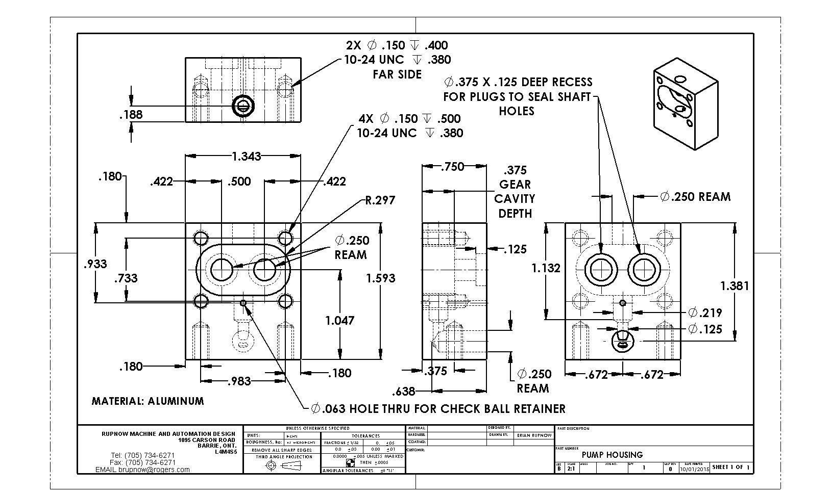
Here we go with the pump housing. Do NOT copy this file. It is preliminary and may change. Updated drawings will be published here at completion of project. What do I see as the problem areas?--Well, two actually, both concerning the cavity for the gears. That .297" rad. gives a diameter of 0.594". (The o.d. of the gear is 0.583". ) So--the holes at each end will have to be bored--There is no standard endmill to give that, So--that and the fact that the bottom of that slot will have to be very smooth.
 
My plan at the moment, concerning the gear cavity is to set the material up in my milling vise with a pair of parallels under it for some clearance, drill and ream the two 0.25" through holes and set the X axis mill stops up so that I can crank the table back and forth between the two hole positions without worrying about reading the dials all the time. Then I will use a 4 flute 1/2" diameter end mill and plunge cut to .375" deep at the center of each of the previously drilled and reamed 1/4" holes. Then I will back the cutter up vertically until it is just clear of the material, then lower it in .010" to .015" increments and crank the table back and forth between the pre-set stops until the material between the two 1/2" holes is removed. Then I will make a steel "test shaft" about 1" long with the major diameter at 0.594" diameter and 1/2" at one end turned to 0.25" diameter.---Are ya with me so far? --Then I set up my boring head and poised over the center of one of the holes, keep dialing it larger and larger and take full depth 3/8" plunge cuts until I reach a point where my "test shaft" will fit into the 1/4" reamed hole and fit into the bored hole. then I will back the boring head up until it clears the top of the material, move the table up to the next table stop and fully plunge cut the other hole at the same setting. Then back the boring tool up vertically again to clear the material, advance it in .010" to /015" increments, and "walk it back and forth" between the two holes to remove the material between the holes, to the point where the slot matches the dimensions on the drawing. If the bottom of the slot isn't nice and smooth, I will chuck up a piece of .594" diameter steel shaft and "burnish" the bottom of the slot with a bit of 600 grit lapping past.--Does that sound like a reasonable approach?
 
Last edited:
Remember that endmills are not flat bottom. Though, I don't think it's enough to matter here. It's not necessary to clear the web between the bores for the gears. If you do, it doesn't have to be full width or depth. The initial 1/2" cut would be plenty. Would this be easier to do in a lathe? I'd be cheating with a CNC mill, but if I was going manual it would be in the lathe.

How much will this pump flow? Last time I calculated a gear pump for single cylinder oiling, the volume was tremendous, even driven off the cam with tiny 0.5M gears.

Greg
 
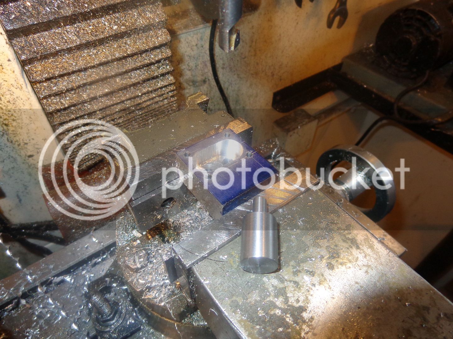
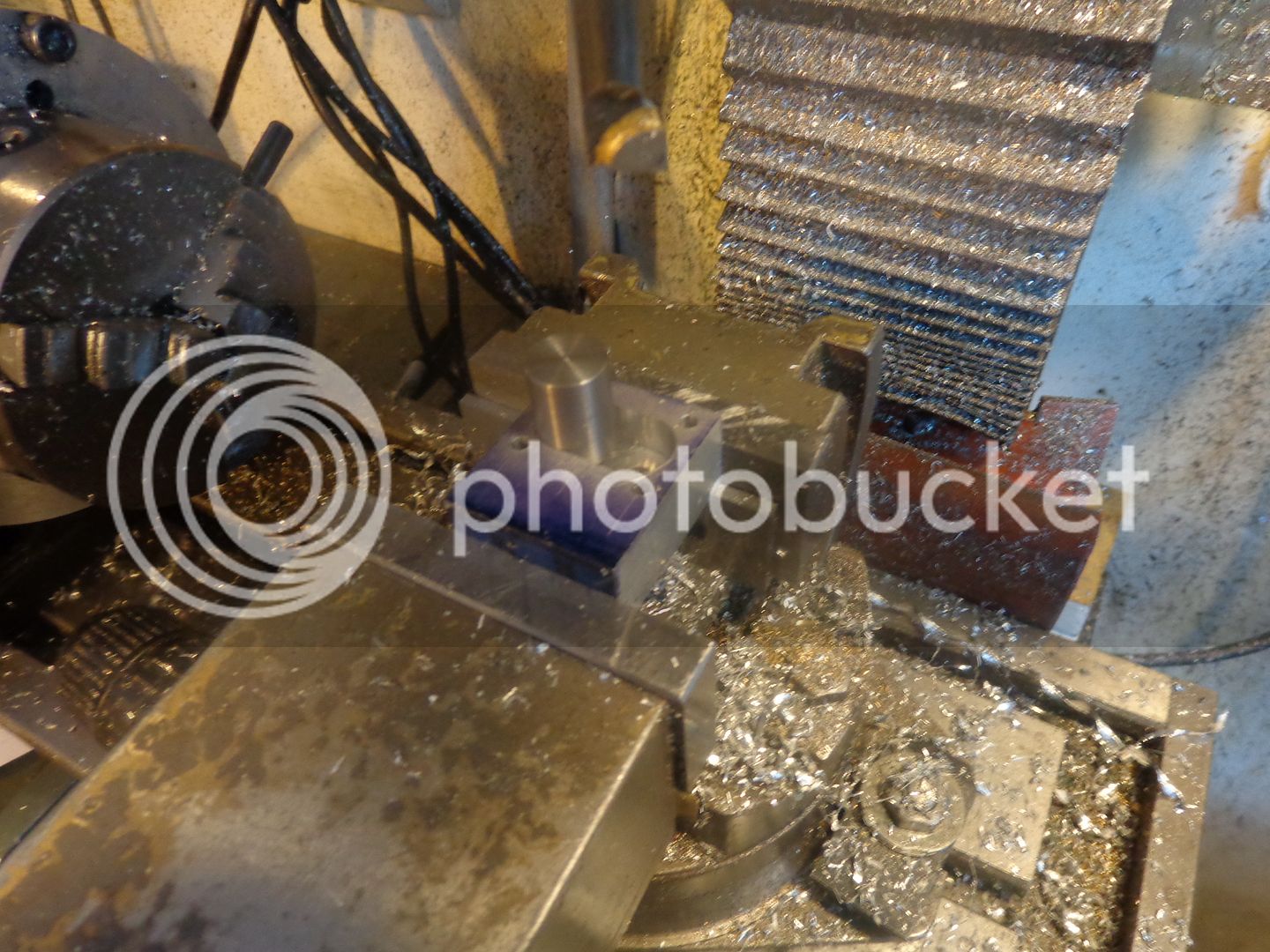
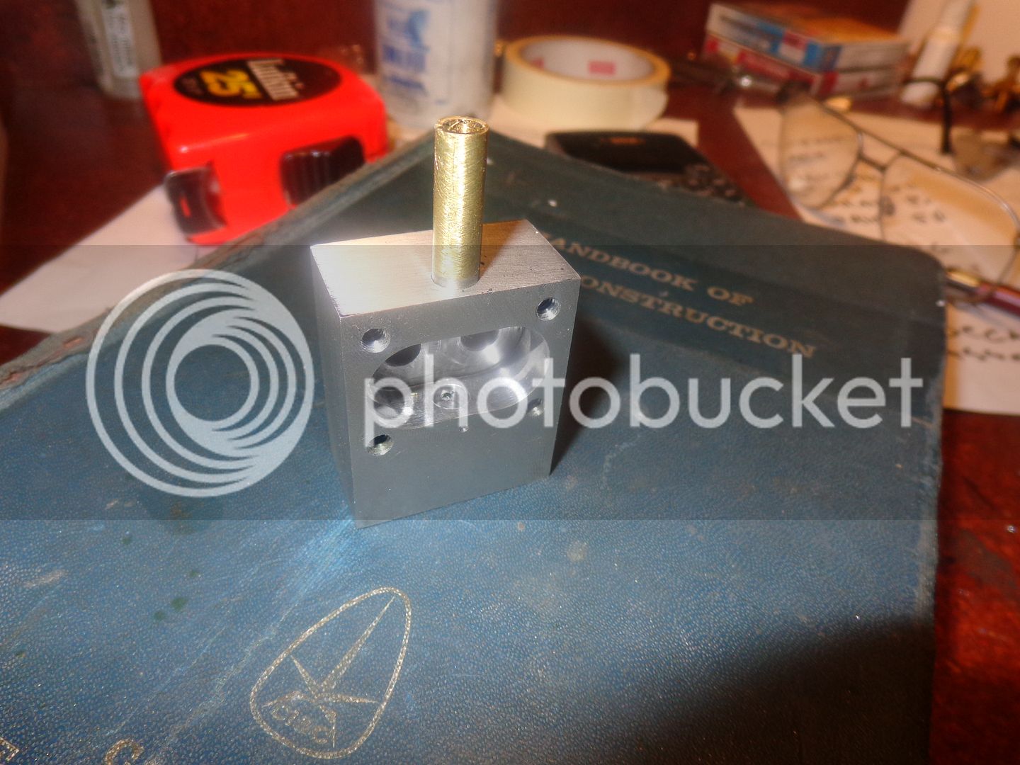
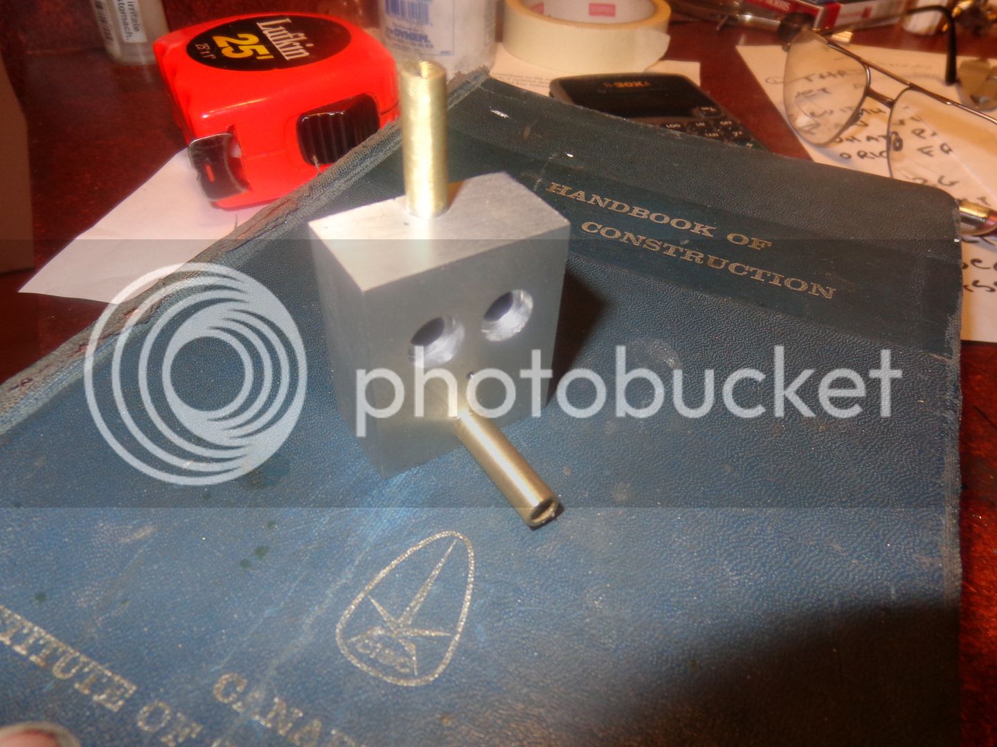
Well Sir!!! I'm happy with this!! Somebody on another board insisted that a .594" hole was too big when running a gear .583" diameter. I'm not sure if I believe him or not, but I tightened the hole up to .587" diameter. Laying in the foreground is the "test shaft" with a large diameter of .587" and a small diameter of 0.25". I plunge cut the cavity with a four flute 1/2" endmill (after putting the 1/4" reamed holes through it.) Then I snuck up on it with the boring head until I could just get the big end of the test shaft into the hole. Then I traversed 0.5" to the other hole center and plunged full depth again at the same setting. Then I took a series of full depth plunge cuts all the way over to the first end in .050" travel increments. The test shaft fits in there, snug as a mouse's ear!!

 
So---That's enough silliness for one day. The pump body is finished. The brass tubes are just pushed in by hand to make a pretty picture. It don't look like much, but that simple pump body has used up most of my day. Maybe I'll cut the gears tomorrow. I wanted to cut the cavity in the pump body first, so that I can make the length of the gears "to suit".

 
Wow. By the time I read this article and get my head around it you're already half way there. Great post Brian. :cool:
 
Unless somebody gives me a really good reason not to, I'm going to make the gears out of bronze. I have a whole bunch of weird shaped bronze offcuts. The only bad thing about it is that I will have to change the lathe over to my 4 jaw chuck to "persuade" some of these weird shaped pieces into .583' diameter rounds to cut gear teeth on. It's a pain in the butt changing chucks.
 
Brian,
You can make gears from almost any material the only caveat is that both gears not be made from the same material. When made from the same material they wear a lot faster than mixed metals. How much faster I can't say but I'm sure you found the frictional properties of metal if you've ever tried to slide a close fitting aluminum rod into an aluminum bore. Now take the same aluminum bore and slide a rod of any other material into it. Voila!
gbritnell
 

Latest posts

Back
Top