Gear pump

Home Model Engine Machinist Forum

Help Support Home Model Engine Machinist Forum:

This site may earn a commission from merchant affiliate links, including eBay, Amazon, and others.
Brian,
You can make gears from almost any material the only caveat is that both gears not be made from the same material. When made from the same material they wear a lot faster than mixed metals. How much faster I can't say but I'm sure you found the frictional properties of metal if you've ever tried to slide a close fitting aluminum rod into an aluminum bore. Now take the same aluminum bore and slide a rod of any other material into it. Voila!
gbritnell

George--I can't say I have knowledge about the wear properties of dis-similar metal gears, but I do know that they seem to run quieter when made from two different metals. This little pump won't see long hours of service. It's more of a "Gee, I never made one of those before!" project. I'm sure it will pump. I just don't know what pressure it will achieve (if any) nor what volume it will pump, nor what rpm it will run at. It is intended more as a little "fun research project" than anything.---Brian
 
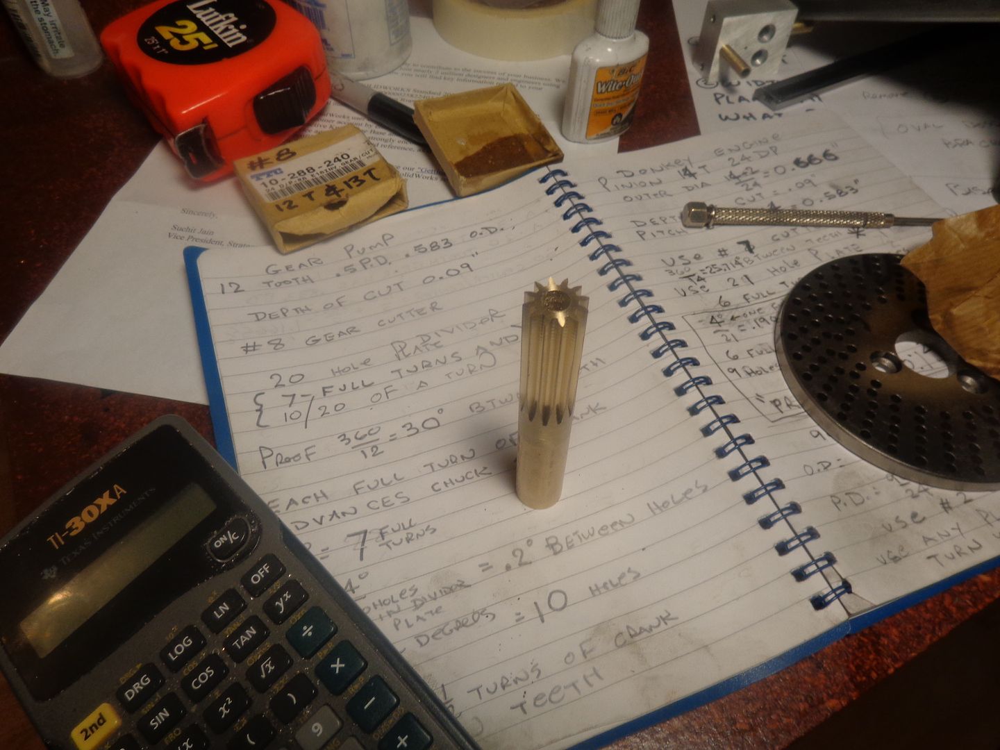
A good way to start the morning!! When I got finished with the rotary table, divider plates, and gear cutter I had an even number of teeth left. Now if I can just cut them to the right length---
 
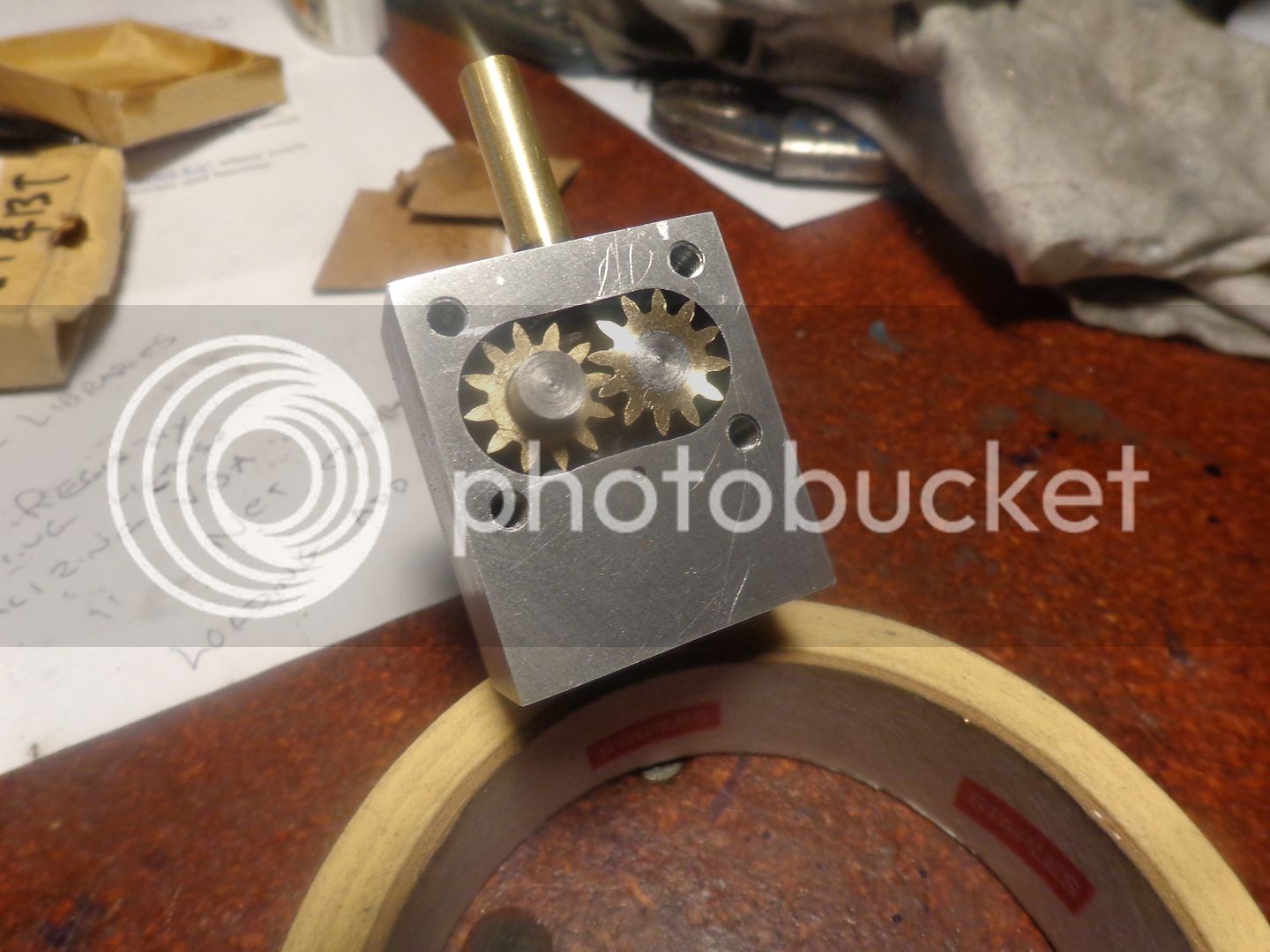
Everything fits and goes round and round when driven by electric drill. That's a good thing. There certainly isn't an overabundance of clearance anywhere. The shafts are temporarily Loctited to the shafts just for test run. I may build the cover side this afternoon. Depends on what my good wife has planned.
 
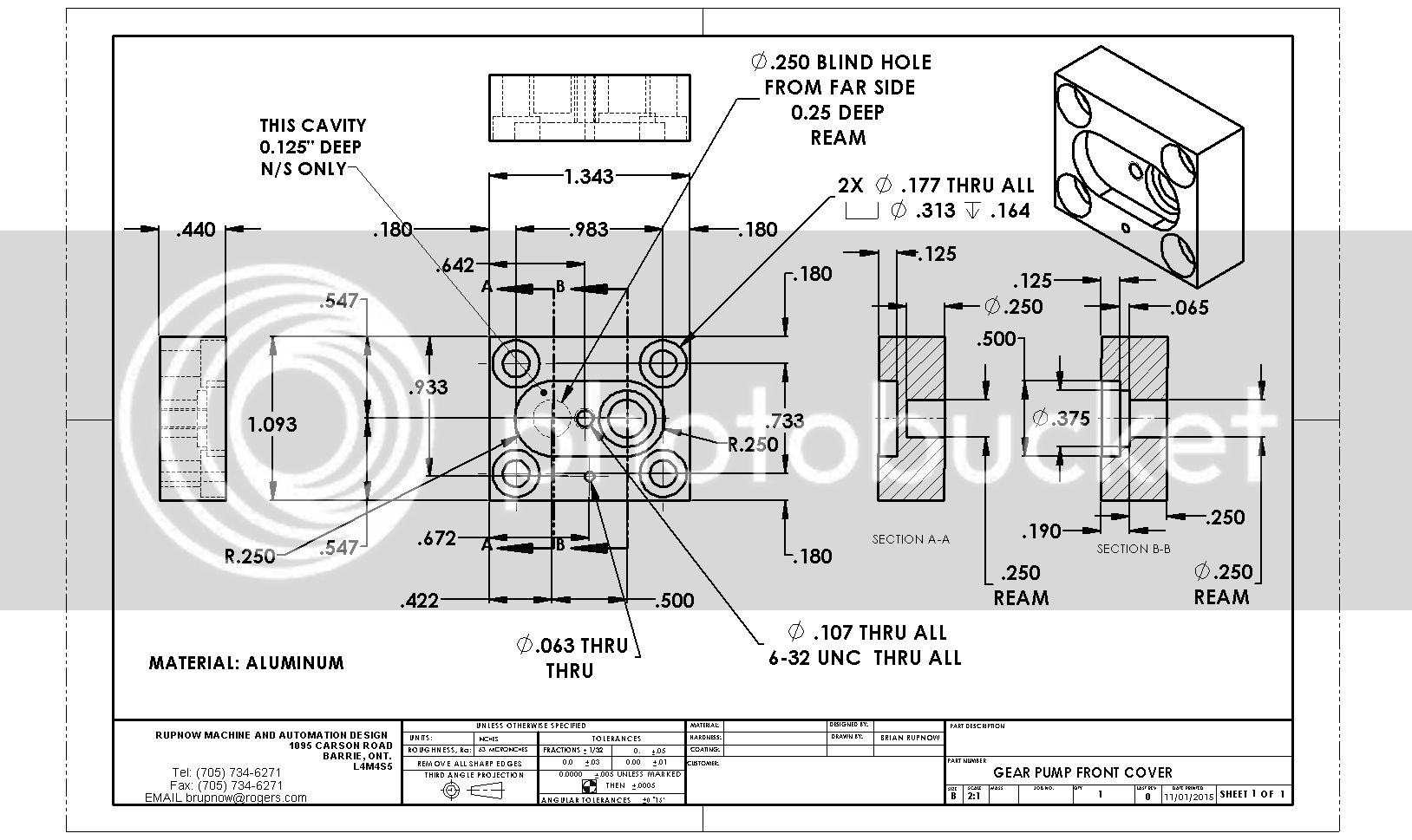
This is where I'm going next. Again, I caution you--don't copy this drawing. It will be "proofed" as I make the part, and some dimensions may change.
 
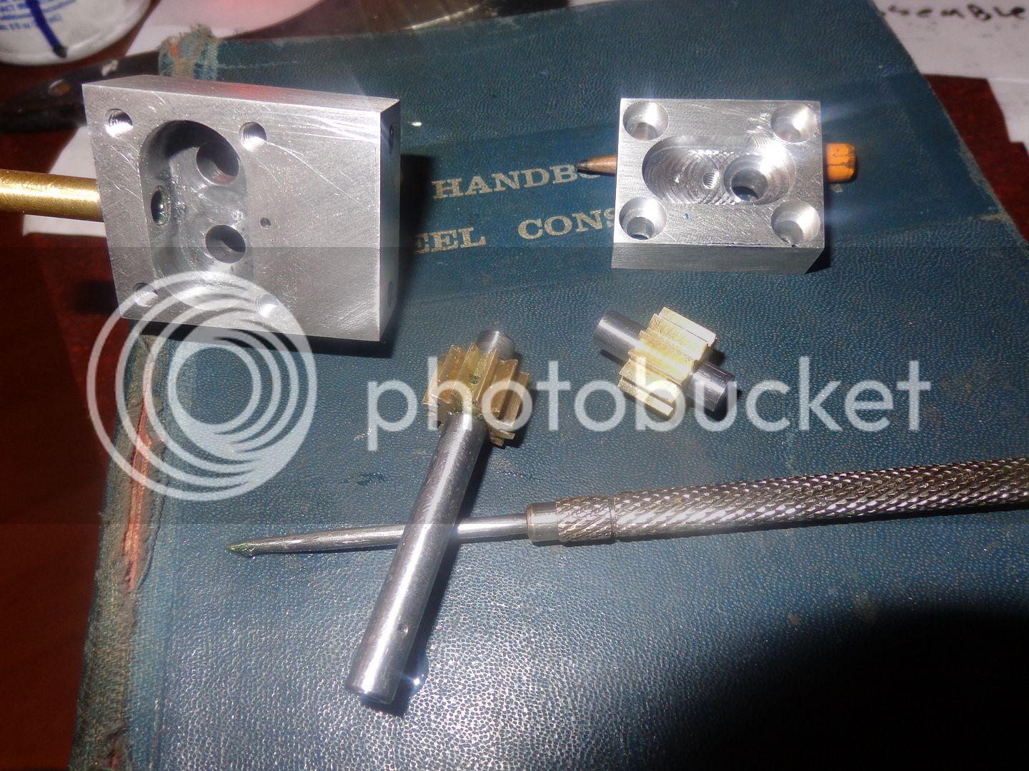
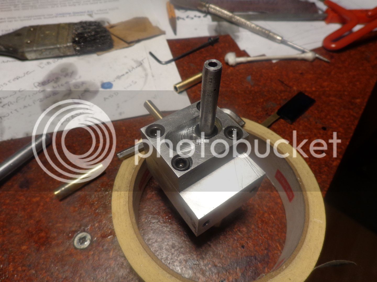
Now, if you squint your eyes a little bit, and look really, really hard, you will be able to see where I have cross drilled the drive gear and shaft and Loctited a 1/16" diameter drive pin thru the hole. The other gear floats on the shaft, which floats in the bearings. You can also see the recess in the cover for the o-ring which seals the shaft. Then a second cover bolts into the big recessed slot in the main cover to retain the o-ring.
 
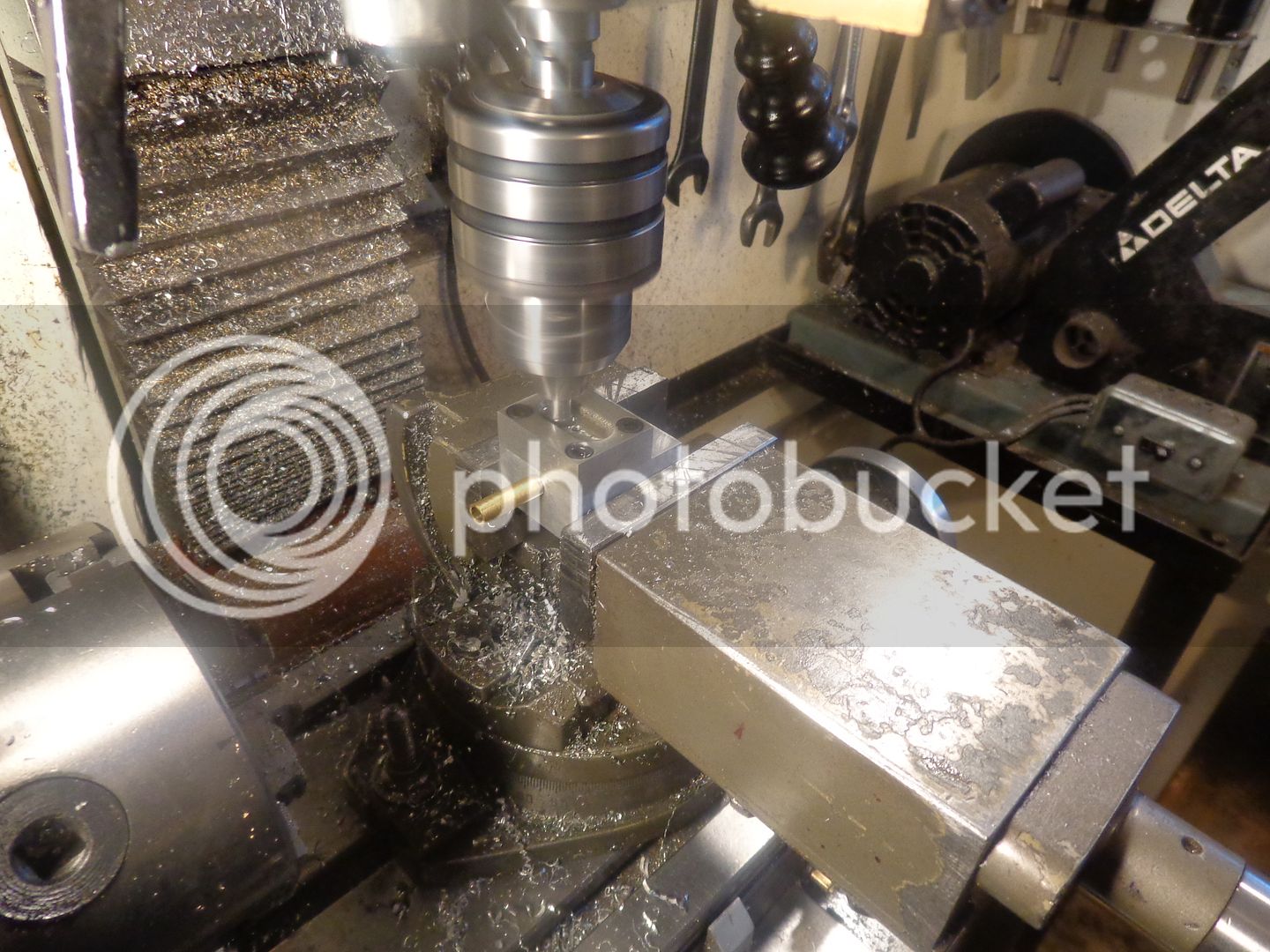
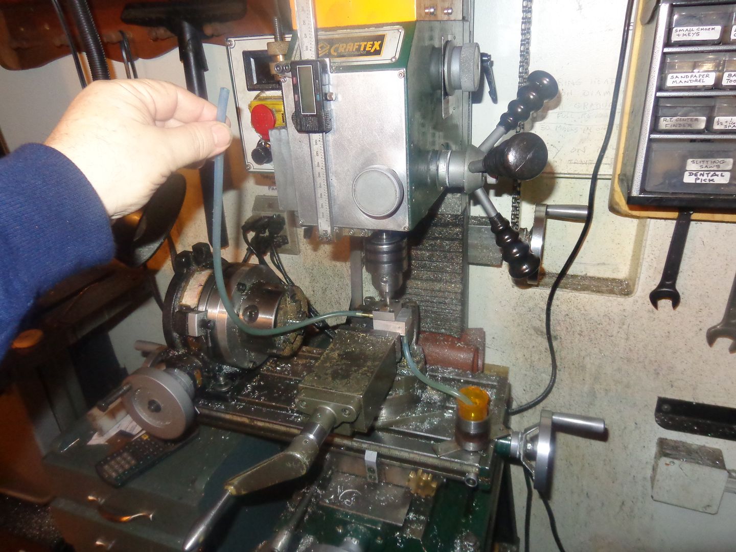
And here we are "running in" the gearpump. I intentionally left both gears about .005" too long, so when I tightened down the cover, I reached a point where the gears would no longer turn freely. Then I backed the screws off 1 turn and ran it on the mill for 2 minutes, with lots of WD40 on the gears. After it started to run freely, I tightened all 4 screws and repeated the run in. I did this in 1/4 turn increments until the screws were all completely tightened. so---there shouldn't be any end gap between the gears and the case now.
 
In this picture you can see the inlet and outlet tubes finished to size and Loctited into place, the plugs Loctited into the back side of the main pump body to prevent any oil drip from potentially sneaking past the shafts on that side, and in the other picture you can see the scuff marks on the inside of the cover plate, from "running in" the gears on my mill.

 
Everything is done and all buttoned up. I have to make up a gasket yet, and I want to make it from the thinnest possible material. I searched all over town today and nobody carries the really thin Teflon gasket material that Gail in New Mexico always recommends. My business card stock is .010" thick. Ordinary printer paper is .003" to .004" thick, but it is too fragile. I will root around a bit and find something for a gasket, then make up a pulley, and we'll try this thing out!!
 
  • Like
Reactions: gus
Use RTV silicone instead gasket. Apply thin layer and away from gear.
 
I ended up using a .007" piece of oil treated light cardboard as a gasket. I have tried the pump out using the mill to power it, but the test was inconclusive. I will make a proper set-up tomorrow and run it off my side valve engine. I didn't have a 3/16" steel ball for the check valve---the balls I had that I thought were 3/16 turned out to be 7/32" diameter, so I ordered some 3/16" balls and they will be here tomorrow. Preliminary indications are that the pump will not lift oil up from a lower elevation, but I will know better tomorrow. EDIT--I just realized as I posted this that my test today was probably inconclusive because the 1/16" diameter hole thru the pump body for the ball retainer rod was open--the rod hasn't been installed yet!!!
 
Last edited:
Preliminary indications are that the pump will not lift oil up from a lower elevation,

The pump will not lift fluid in a height due clearance between gear and pumphouse make airleakage, better to have pump soaked in the fluid or under level of fluid if the pump is mounted outside the container for fluid. Gearpump work very well with fluid inside.
 
Things are looking up!!! I plugged the 1/16" hole and retried the pump. The vessel full of oil was 4" below the pump, and I started the pump dry, with no prime. It sucked the oil up from the vessel, and then was able to pump it 24" vertically (that's all the tubing I had). It is sucking air somewhere, because I am using clear tubing and I can see a lot of air bubbles entrained in the oil coming out of the discharge side of the pump. However, the pump does work. I don't know yet how good or how consistently, but it does indeed work.---More tomorrow.
 
Last edited:
Next project. Hydraulic ram for small log splitter ?? :rolleyes:
 
  • Like
Reactions: gus
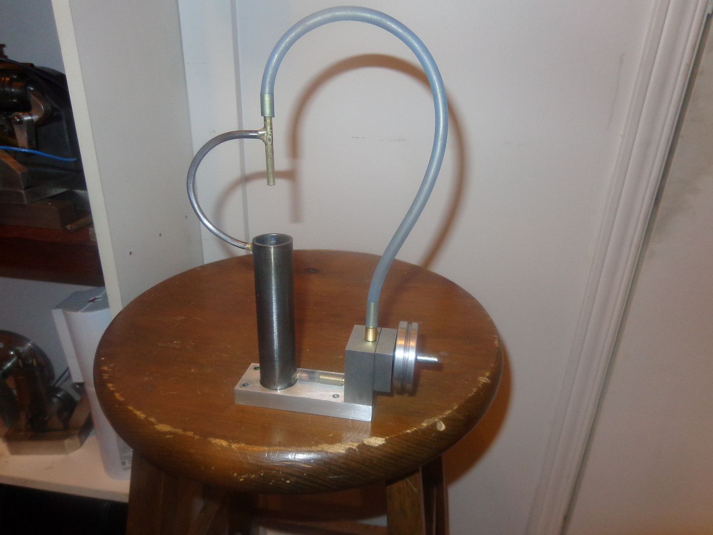
We are ready to Rock and Roll!!! By the time you see this, the first test will be underway. I dismantled the pump and put in a 3/16" diameter ball for the check valve, and it works great according to the "Suck and Blow" test. The 1/16" ball retainer pin has been Loctited into position, and a dab of Loctite put on the #6-32 o-ring retainer plate bolt threads to seal any air leaks. I salvaged a 1 7/8" diameter pulley off some old project (it was a 5/16" bore but I sleeved it down to 1/4".) I used a piece of 1" o.d. steel tubing for my oil reservoir, and that funky looking curved part is just a solid 3/16" rod to support the upper brass spigot that my clear flex line attaches to. From the centerline of the pump gears up to the top of the loop in the clear flex line is a total of 9". The first test will be conducted using some cutting oil, because that's what I have handy. It is very cold out in my main garage where I test run all of my engines, so I will probably conduct this test in my warm little machine shop, using my mill for power. If it works as good as I am hoping for, then I will move the operation out to the main garage, turn on the furnace out there, and make a video of the pump being driven by my side valve engine.
 
Brian,
The picture in post #23 which shows the gears in place looks to me like it will cause a problem. The reason being is that the gear teeth seem to be too thin and won't seal when rotating. The mechanics behind this type of pump is when the gears are rotating they carry the oil around the inside of the housing. Once the oil gets to the opposite side of the pump the close meshing of the gears seals the exit route for the oil and pushes it through the outlet.
To have any kind of pressure efficiency all of the dimensions need to be as close as possible, O.D. of gears to housing, width of gears to cavity, and mesh of the gears.
gbritnell
 
One message to all those who have pointed out that this gear pump will not create much pressure because of the gear tooth shape. I didn't set out to make a high pressure pump. I set out to make a pump. I have a set of 24 DP gearcutters, and that is what I used. I know that there are specially designed gears to work with fluid pumps to create high efficiency and high pressures. When I began this project, my intent was to make a pump that would lift a fluid from a low elevation to a higher elevation, using what I had. If it had much pressure, well, sure, that would have been a bonus.---But--I never intended nor expected it to be a high pressure pump.
 
Last edited:
One message to all those who have pointed out that this gear pump will not create much pressure because of the gear tooth shape. I didn't set out to make a high pressure pump. I set out to make a pump. Period!!! I have a set of 24 DP gearcutters, and that is what I used. I KNOW that there are specially designed gears to work with fluid pumps to create high efficiency and high pressures. When I began this project, my intent was to make a pump that would lift a fluid from a low elevation to a higher elevation, using what I had. If it had much pressure, well, sure, that would have been a bonus.---But--I never intended nor expected it to be a high pressure pump. If I had wanted a high pressure pump, I would have marched my fat old butt down to the hydraulics store and bought one. This pump is an absolute success in my opinion. It fulfills the function I had intended it to.----Brian

I’ve seen better reply to group members opinion then this one
Specially after asking group member's opinion in post #4 and #13:hDe:
 
Last edited:

Latest posts

Back
Top