GEA, a 3.5'' live steam narrow gauge locomotive

Home Model Engine Machinist Forum

Help Support Home Model Engine Machinist Forum:

This site may earn a commission from merchant affiliate links, including eBay, Amazon, and others.
Intermediate state:
223B0D83-8E5C-420F-8306-D113E6F67FB2_zps6xhmjdfc.jpg


And a near finished one with a very bad camera
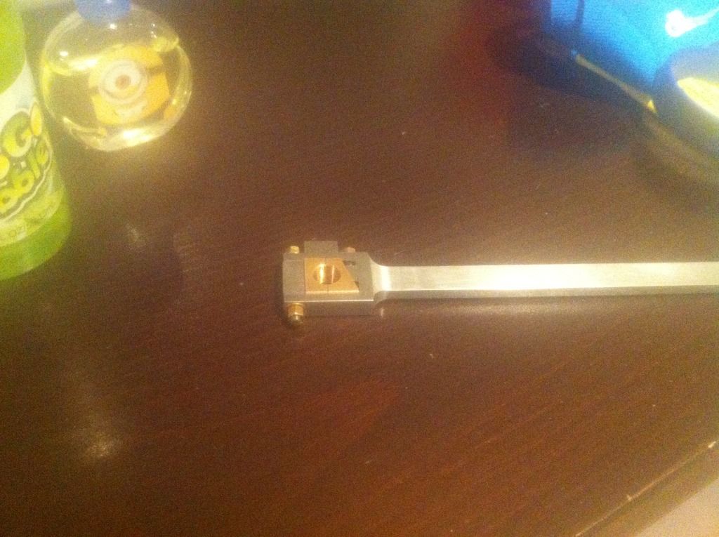
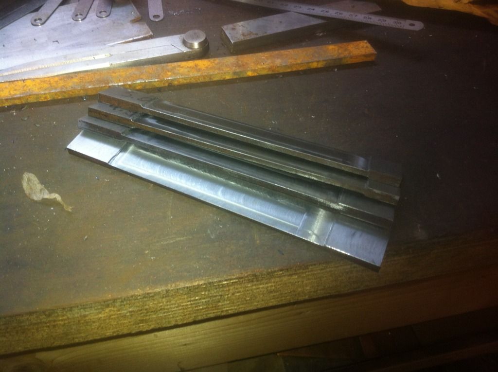
I had quite a lot of headaches on the radii - specifically on de long side. I did not want to make a specific setup tool. I thinned down the center part and tried to blend in the radius while having the rod 'head' in the vice. Sorry no pics. Due to this not very stiff setup i had quite a lot of work to remove the machining marks.
But all in all it came out sufficiently ok.
Henk
 
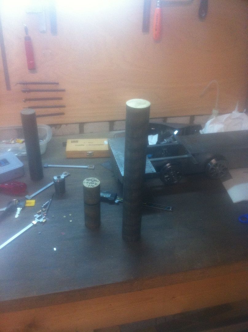
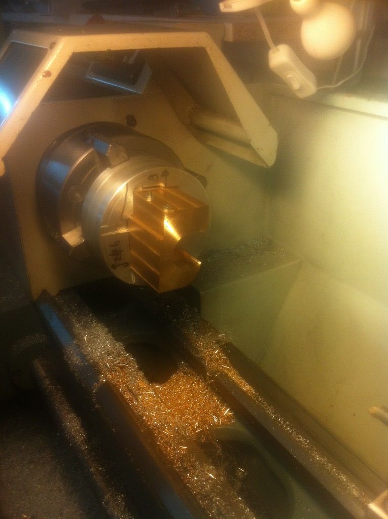
So these three pieces of mystery bronze need to be converted to two cilinders.

They will be in three pieces. The thick bar is 55 mm and will be used for the cilinder itself. Btw it is long enough to support redoing both cilinders. Not that I look forward to it, but it does ease my mind.
 
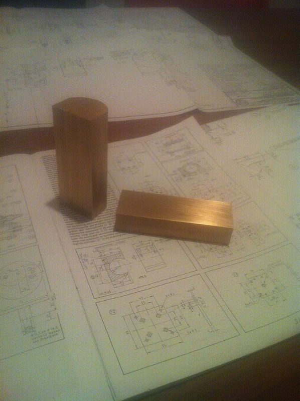
Short piece reduced to a bar and the other bit to partly round/ rectangular.
The length is still for two cilinders.

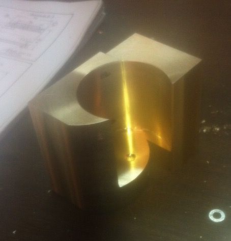
Here you can see how they will be used together ( for a single cilinder)
 
I am following this post with great interest and can say you are doing an excerlent job.A previous comment was to not build too tight but halfworn
condition.This should be held in good stead.The hornblocks need to be radiused on the inside of all 4 edges to allow the axle to move up and down out of level or to rock to suit track conditions and avoid binding
 
I will take that into account but only after trial on an actual track. I want to see whether the track width seems ok and the wobble not too bad. This means only reworking once.

Boring the hole in which the actual cilinder is mounted requires a jig:

The pieces are longer to enable screwing them to the jig from behind. The actual boring is interupted, but sufficiently rigid. The two pieces to be bored are screwed together.
 
And after boring, now need to remove the lower part:
 
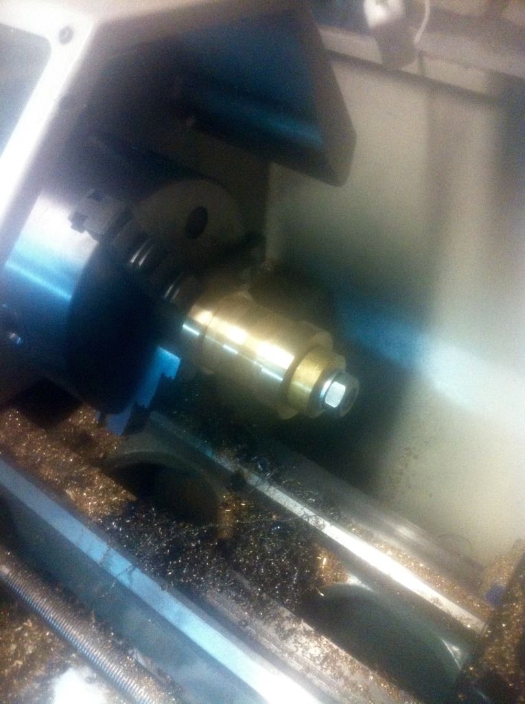
The actual cilinder is an easy job done on a mandrel. Accuracy is not really important as final dimensioning is done after soldering the assembly.

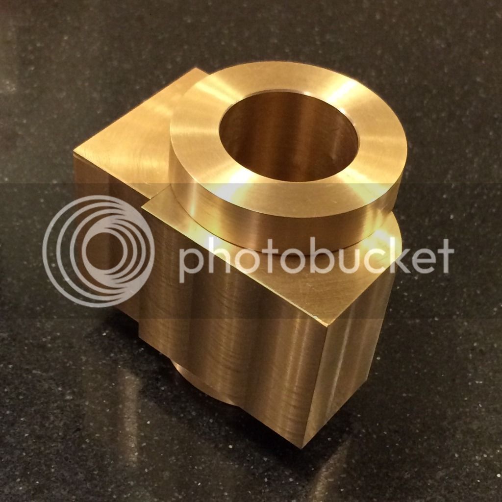
Trial fit of all components:

The two non cilinder parts are screwed together with bronze screws thereby keeping the cilinder in its place.
 
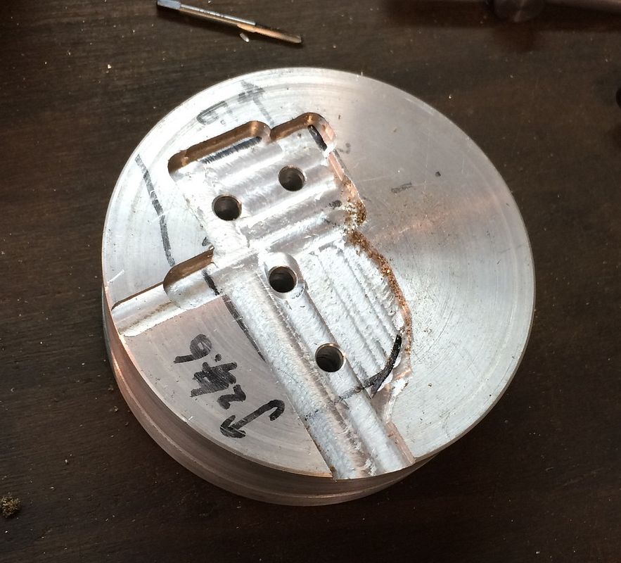
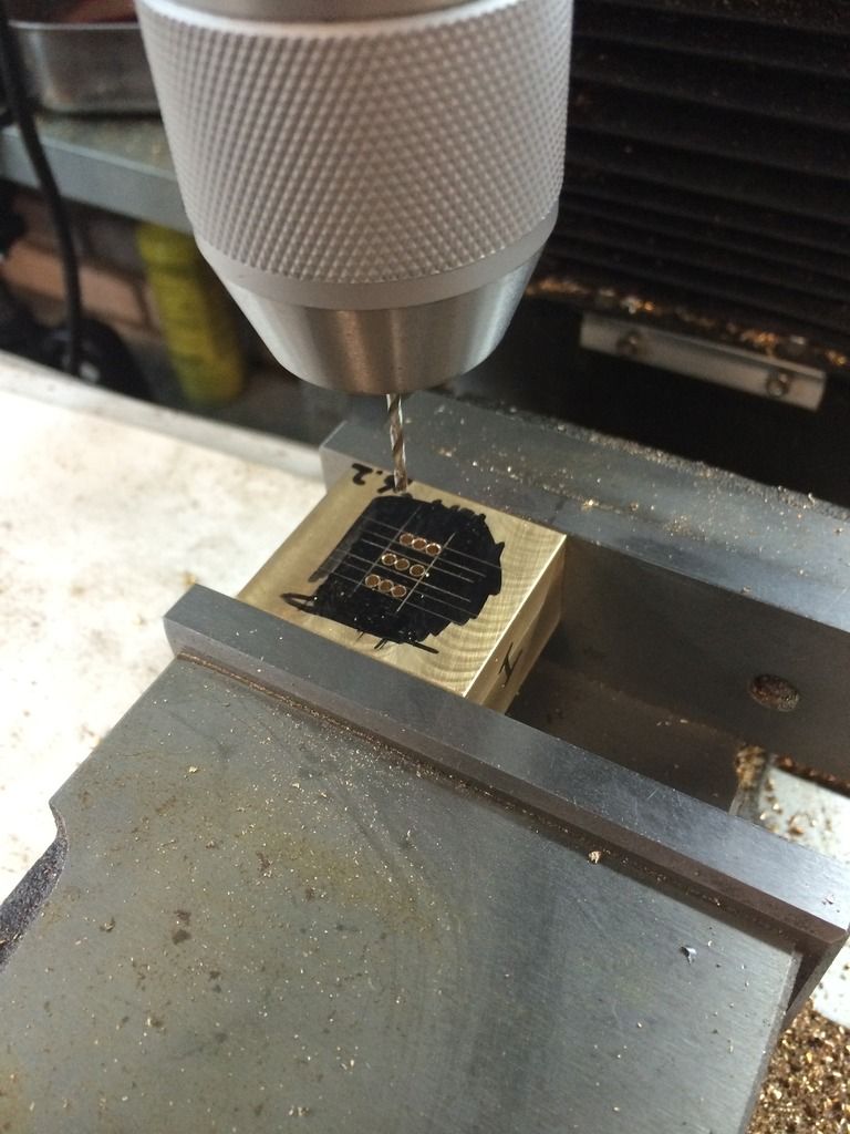
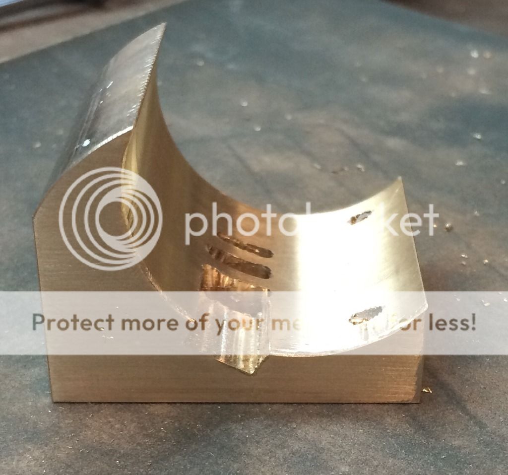
To hopefully help the proces later on I drilled/milled the steam ports before brazing. . Main reason for doing so was to mill the channels as well. . Turned out to be a stupid idea. What I did not realize was that the cilinder flange is smaller than the depth of the channel that I just made. Marginally so, but too much to fill with solder. So therefor i filled up the channel with a piece of bronze, screwed into position with a bronze screw. Should be totally invisible. But at least I captured it before doing the same for all channels.
 
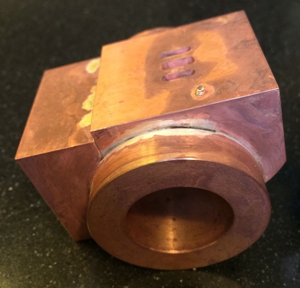
Even though I filled up the hole, the seams were apparently too big- as you can see below:
Not leaktight. You can also see that the screw was not properly soldered - I had hoped that it would wick up. I also learned that it took longer than I expected to get it up to temp. So apparantly the mass is really relevant- not just the heat loss due to bad insulation/ Large surface area. I forgot to take pics after the second try of soldering. In this second try I made sure that gravity helped the flow of solder instead of orienting the cilinder such that I had a good view of the seam. I know my place now... Also now the screw is well covered.
 
After boring to size and some cleanup it start looking usable again:
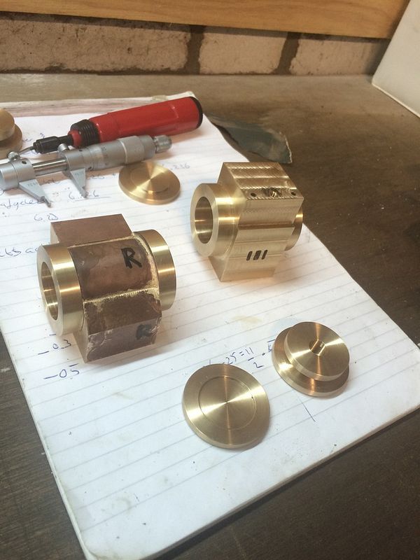
You can see the tapped hole in the right hand side, that will be plugged, just prior to soft soldering, and the cilinder caps in progress. The 'R' is for the right hand side , and the flange where it is written is the one faced in the same setup as the bore.
 
Btw minor problem is that on one side, the cilinder is 0.03 mm larger (at the end closer to the chuck). I still do not understand why. One possibility is that due to flex where the tailstock side ( due to the large distance to the chuck) is deflected. But then it would be deflected by the cutter, but then it should be touching the workpiece. And what I noticed is that the boring bar kept cutting at the chuck end. It no longer touched the tailstock end! And I did between 5 and ten spring cuts. The other option could be misalignment of the headstock, but I did a test ( external turning ) afterwards to exclude that. Anyway, fact is as is, but I would like to understand to be able to prevent it from happening next time.
 
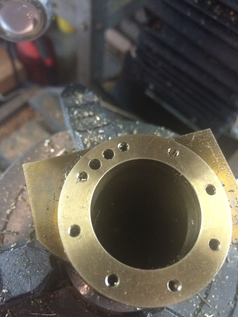
I intended to try chaindrilling the passage from cilinder to steam ports with 4 drill locations. The drawing called for 2.5 mm by 8. I started with 1.8 mm or so. First hole : drill broken ( just a small bit , rather deep) . Second hole same story (1.9 mm). I really am a slow learner. Stepped up again in drill size. Bummer. So now I had 4 half holes with bits of drills of various sizes. Sorry - no pics. That was definitely the point in time to stop. And think. Next shop time milled using a 2 mm mill from a deep hole towards a hole where the broken drill was not very deep. I hoped that joining the two holes would enable me to acces the broken drill. Of course the cutter broke as well. But it was easily retrieved.
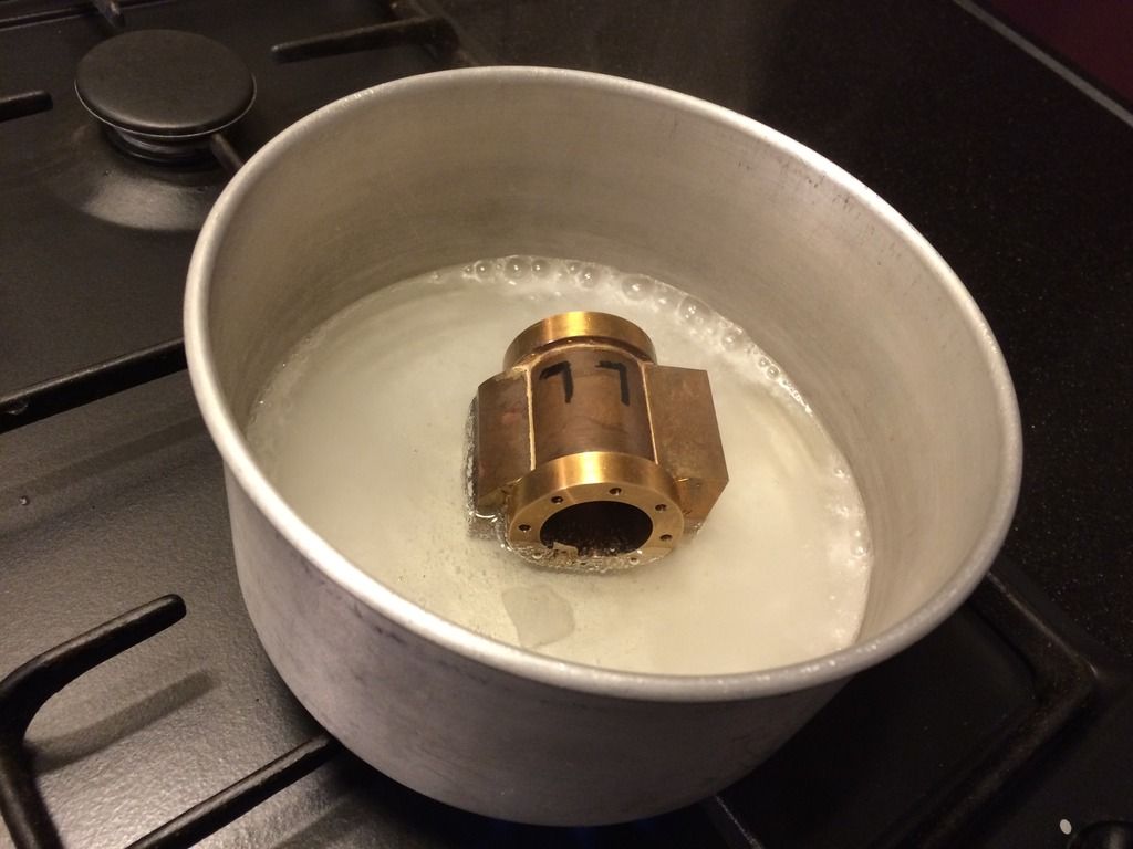
Next thinking and googling. Found the references to alum to remove broken bits. The fact that it could take long did not bother me at all. As long as I can do other usefull stuff it does not really cost me time. And I really don t want to remake this thing. So I bought some alum and put the cilinder in, on and off boiling it to speed up the process.
I think the main reason for the broken drills was that due to the partial channels I made before, that when the drill broke through, half of the drill was still seeing material and the other half not. This caused the drill to bend and break. If so, I had no way to change the internals of the cilinders. The only way I could see is use bitter drills. If I recall correctly stifness is proportional with size^4. So I wanted to go in with the biggest drill that still leaves sufficient meat. It also meant that I will not open up the holes. And also that I would stick to holes only. I settled for two 3 mm holes.
 
That last picture was just to show my happiness at not ruining the second cilinder after choosing the bigger drill. Not wanting to redo a cilinder means I really really don't want to redo a pair!

Some stuff to keep me occupied while the alum was simmering/ just waiting cold.


The front cilinder covers are a bit loose to my liking, but i'll see later on.
 
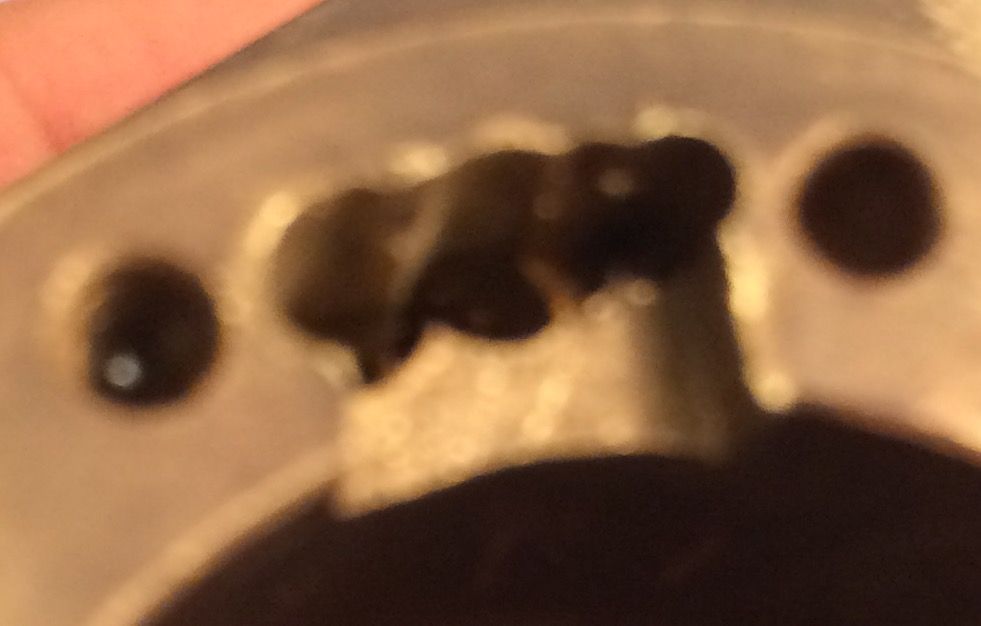
So I left the cilinder in the alum for say 2 weeks or so. I tried feeling with a needle whether it worked or not. I was sure about the first and second hole, but not 100% sure about the last. Plan: start with milling with 3 mm mill on first ( left) hole to make a clear start for the 3 mm drill. This proved to work. But by blowing through it I really sensed a lot of flow resistance, so thatwas clearly not enough. But the second hole I wanted to stay clear of the location I was not sure about. This meant milling and drilling overlapping the hole I just made. Boy that was a bit nerve wrecking.

End result is far from beatifull, but it'll do for me. Glad to have finished this phase.


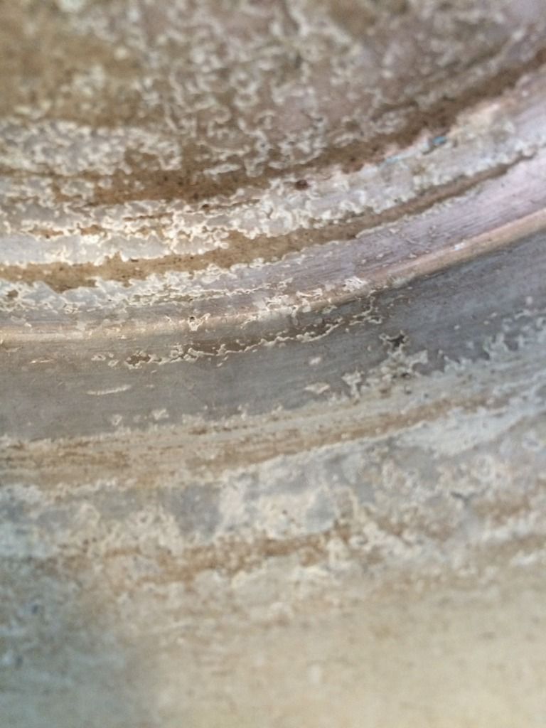
Btw: I read that alum leave aluminium unaffected. Therefor it seemed ok to use an aluminium pan. However the surface of that is now very very pitted. This may not happen if you only have aluminium and no bronze (my chemistry is very rusty). Here a close up of the pan:

The surface of the bronze seems to have a very thin layer of something, but nothing seems to have affected the surface finish.
 
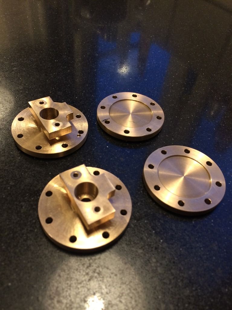
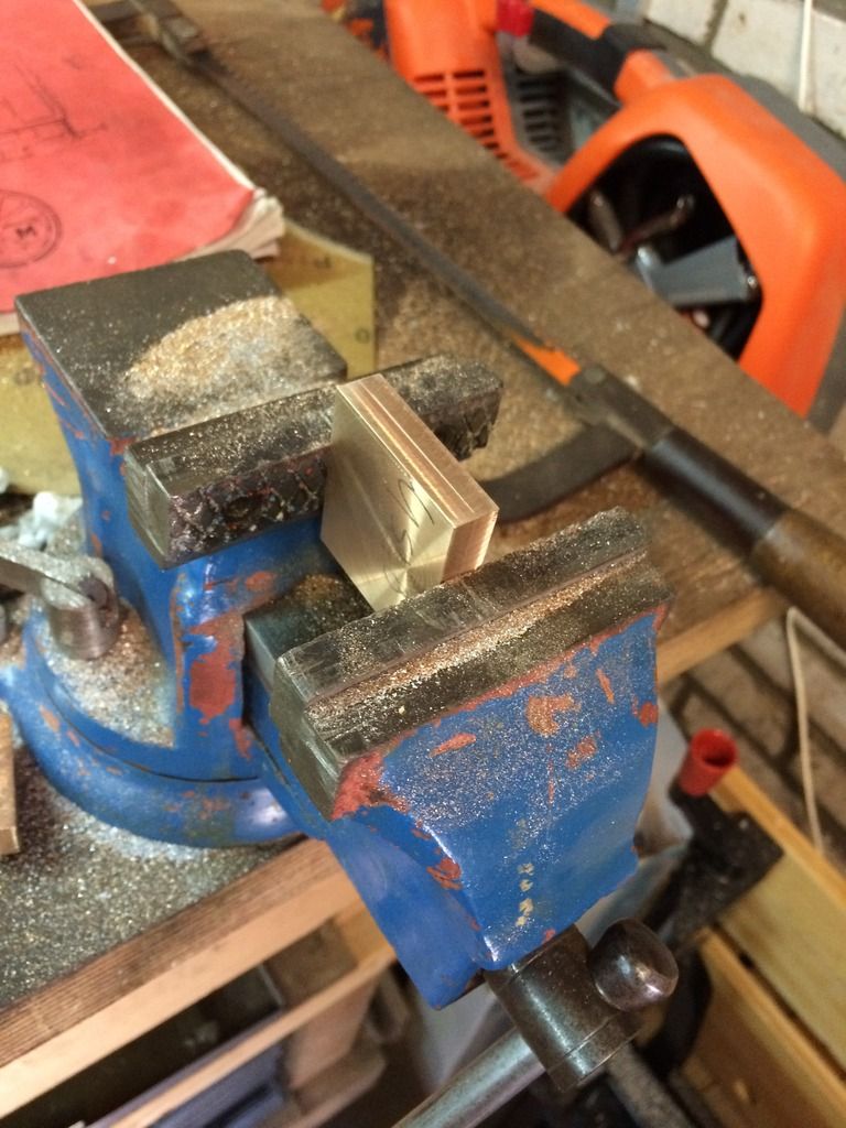
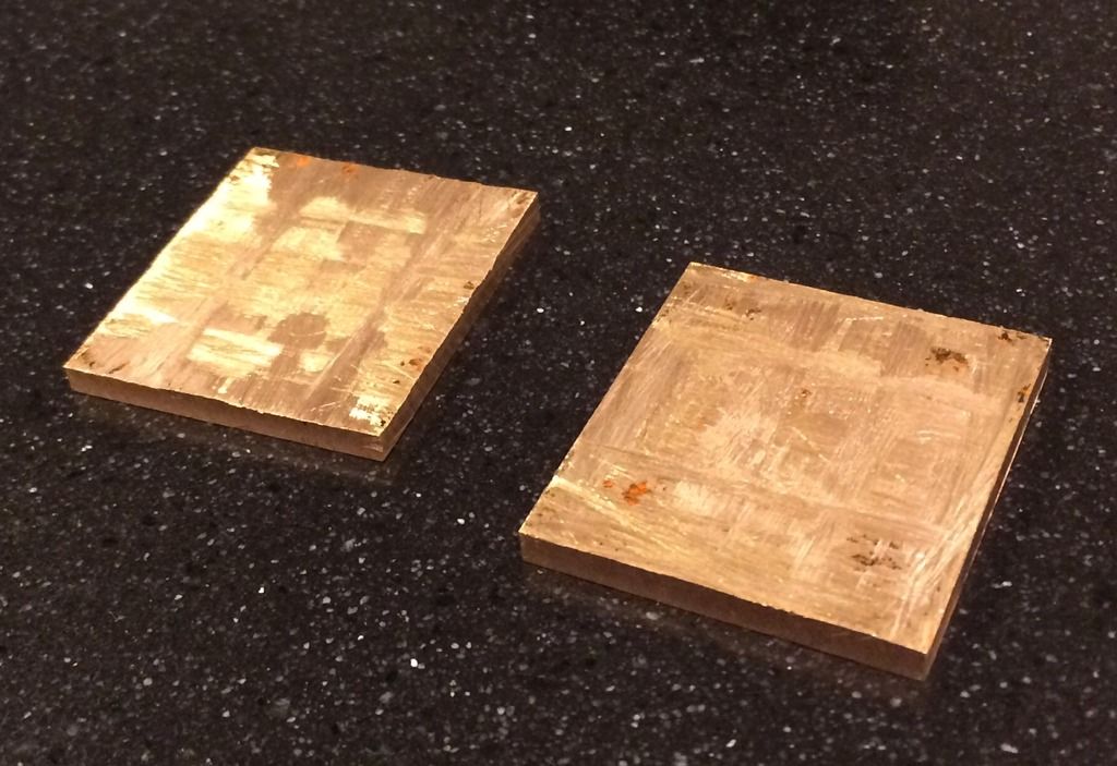
The drawings called for bronze for the steam chest covers: 3 mm thick ( x 36 mm x40mm). I happened to have a 9 mm thick piece. So with moderately careful sawing this should produce 2 pieces.


And it actually worked out ok, with 0.5 mm on one side and 1 mm on the other side. And it does not take that much time after all. But I admit that I am a bit more apprehensive in drilling holes in the part than if it been from a piece of 3 mm brass
 
Last edited:
Speaking about drilling holes: steam chest, cover, cilinder=3x8 holes. On each cilinder equals 48 accurately placed holes. And that equals a personal business case for a dro. I Postponed for 5 years mainly because it seemed out of balance in price (800 €) compared to the mill itself (1300 €). And maybe because it feels a bit like cheating. But if I am ever going to finish this project, I need all the speed gain I can get.

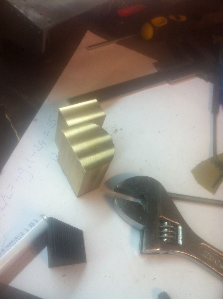
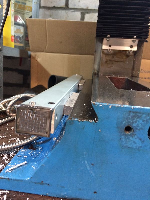
So buying it was easy. The seller advertises the set as directly fitting on the mill (hbm bf 25). This is very much not true. As an exemple I would have expected a part or directions to make the angled spacer as seen below:


It did come with the usual set of brackets. So as I realized that I had to regard it as a set of raw material then it was workable within a few evenings. One of the puzzels is that you need to plan machining a bit more with a partially disassbled mill.

I also spoiled myself with power feed. I go to that shop every few years- it only makers sense to make the most of a single trip right? There I misjudged the weight impact. I used to have the vice on the right hand side of the table. That way I had most of the table out of the way of my workbench. Now with the weight of the power feed all the way over there, dials feel sluggish. So therefor I move the vice such that for normal usage, the center of gravity is centered. Which means I lost more space on my workbench than I anticipated ( which was nothing). Still not going to remove it though. I'll give it some time.
 
Long time since last update. And a lot less progress than i had expected. But at least the old posts have the images visible - although with the pb watermark.

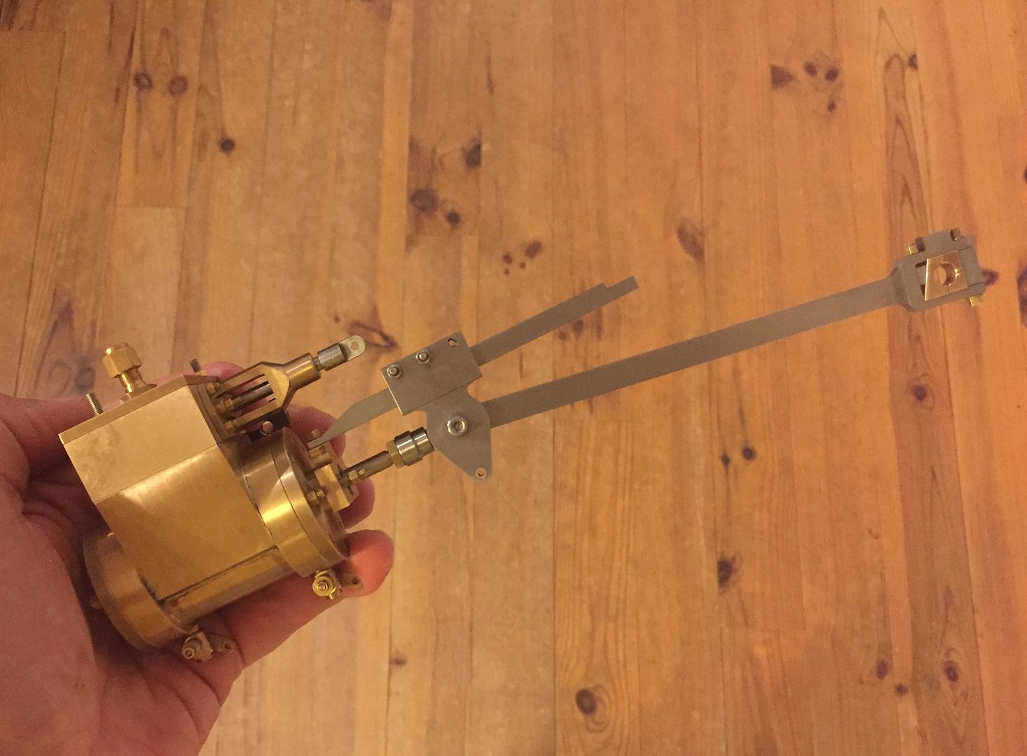
So below full cilinder assembly with crosshead and guiding. Draincocks are shopmade - i’ll see how they perform at full pressure. No piston rings yet.
 
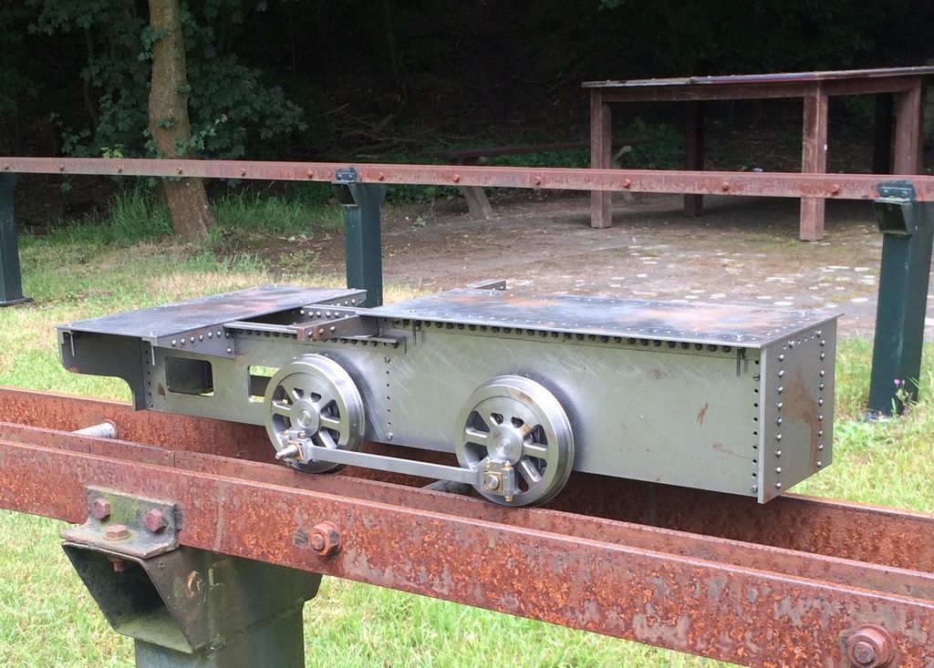
At some point also tried the frame on wheels on an actual track:


Seemed not a problem. Got some advice as well from local enthousiasts.
 

Latest posts

Back
Top