Gassie - National Gas Engine

Home Model Engine Machinist Forum

Help Support Home Model Engine Machinist Forum:

This site may earn a commission from merchant affiliate links, including eBay, Amazon, and others.

Jasonb

Project of the Month Winner!!!
Project of the Month Winner
Joined
Mar 30, 2008
Messages
4,270
Reaction score
1,630
Location
Surrey, UK
It has been a while since I posted a build thread here but thought I may as well show one.

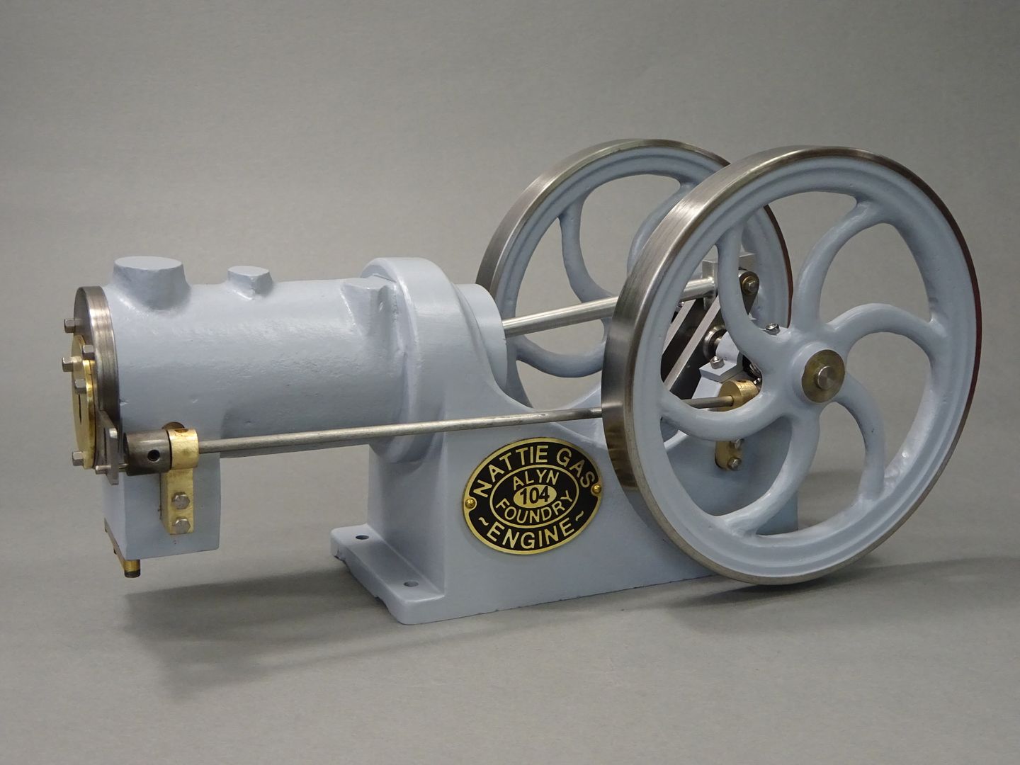
It all started when I said in another thread about Nattie*.

"Could not help thinking while I was running this that it would be fun to see if the cylinder could be sleeved to form a water jacket, gears changed to get 1:2 ratio, add a couple of valves into what was the exhaust block (turned on it's side) and a spark plug or hot tube in the head, about 24mm bore should work"

A few months later Graham Corry of Alyn Foundry sent me a pair of gears that he had been applying the special brown coating to for a number of years together with some Nattie castings so I could hardly refuse the challenge to make a sister engine called Gassie:-[

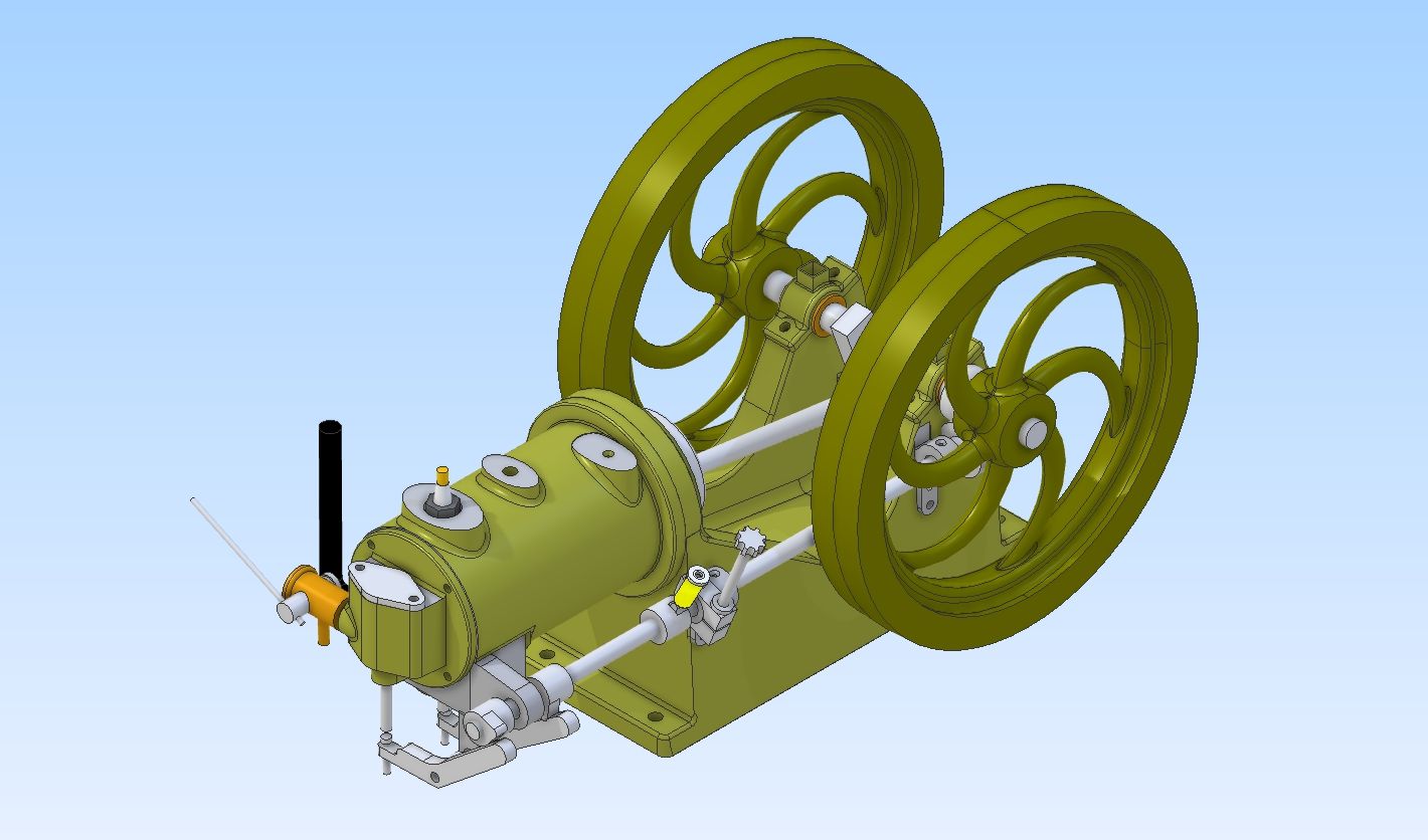
Although this engine does use castings I have put it under "Own design" as I did design the patterns for 50% of the castings and have modified the others together with designing all the remaining bits. This was done over a few evenings with Alibre along the same lines as Nattie which is to have an engine with the look of an early National Gas Engine.
Shaftie_ass.jpg


I ended up keeping the exhaust block the same way up as that also kept the various bosses at the top of the cylinder in the right place making use of the rear one for a spark plug as I have seen on some full size engines. A liner allows for water cooling which is via the middle boss and a drilling through the underside. A new head houses the inlet valve and boss for the carb. A larger dia solid crankshaft takes care of the more powerful stroke and a thicker side rod carries the two cams and electrical contact for the ignition.
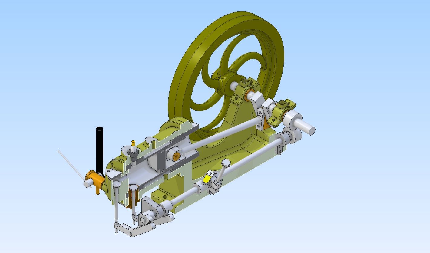
Shaftie_section.jpg


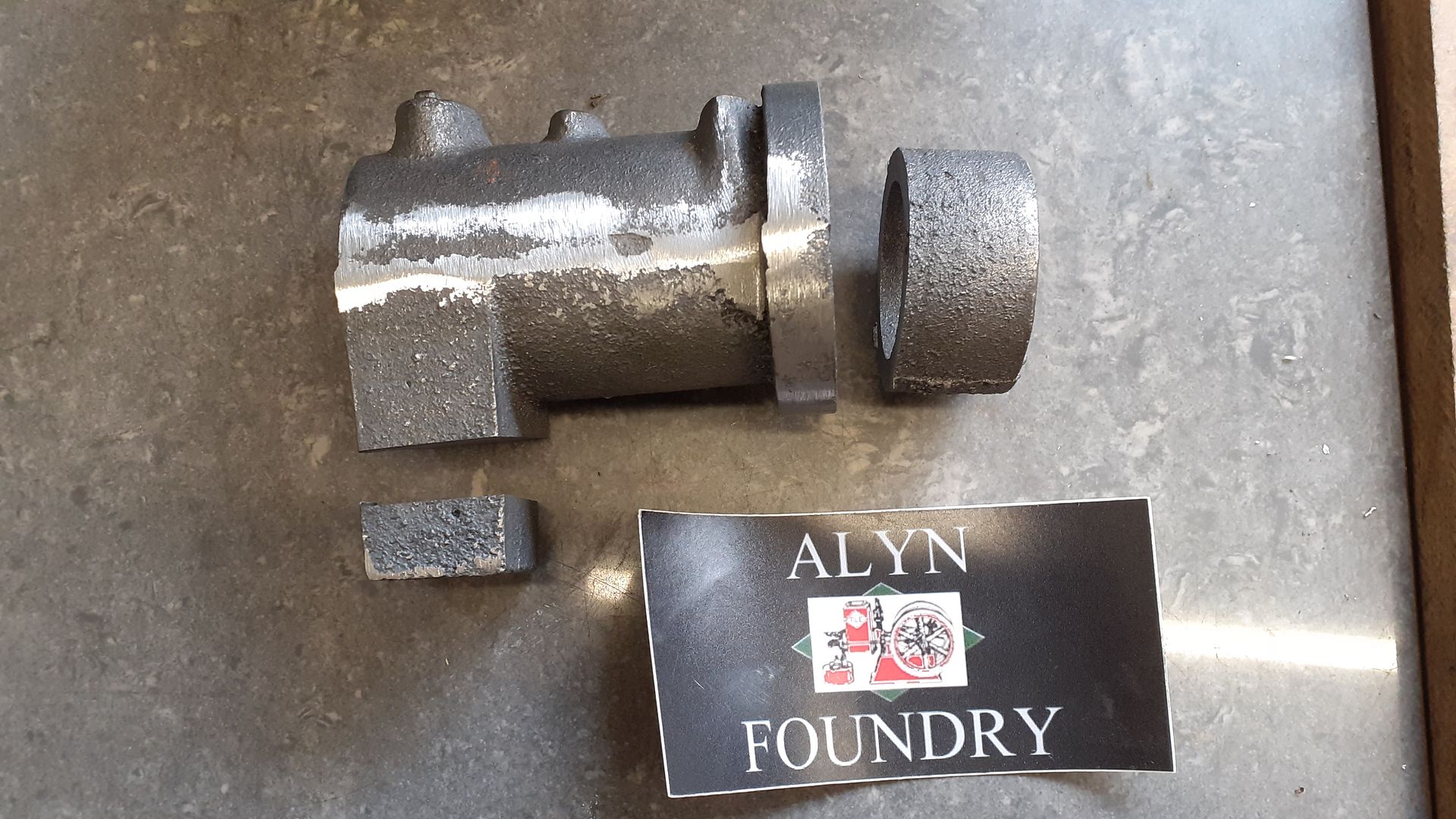
First job was to get rid of what was not needed.
20240227_141240.jpg


*For those that don't know "Nattie" it is a flame licker very loosely made to resemble an early National Gas Engine

 
Yes that is why I said "gears changed to 1:2 ratio" I class 1:2 as a reduction and 2:1 as an increase as one equals 1/2 (reduction) and the later 2 (increase to double). Although the teeth are not shown on my 3D images the skew gears are both of the same OD but helix angles different so you can fit twice as many teeth onto the cam gear as you can the crank gear. This also keeps the flywheels close to the frame rather than having to space them out a long way which would be needed if the cam gear was twice the diameter of the cam gear. common full size practice too.


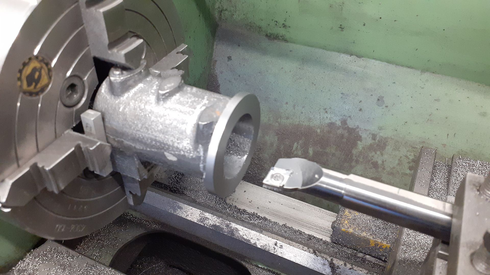
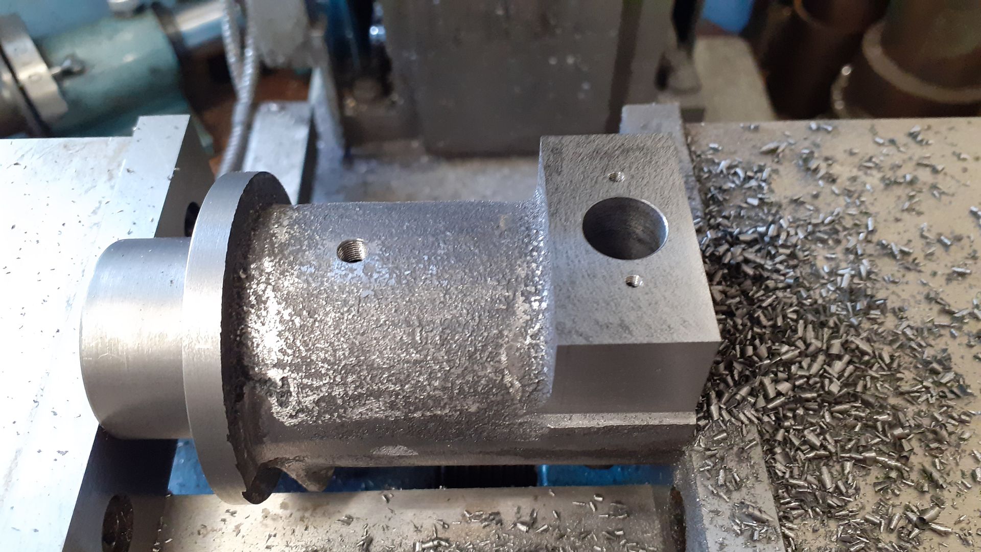
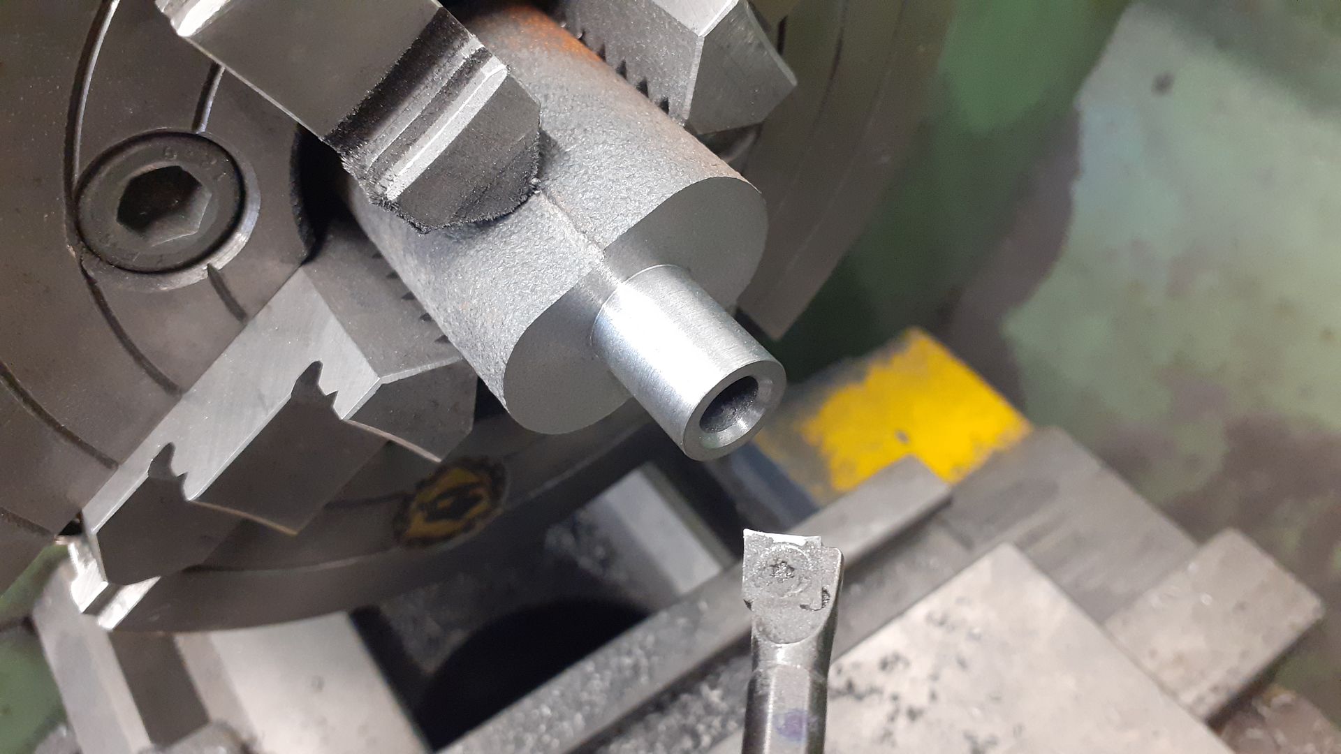
With the unwanted metal sawn off the cylinder jacket casting it was held in the 4-jaw to face the end flange, turn the flanges OD and finally bored to accept the liner. I spent some time getting the sides of the casting as square as possible to the chuck face as well as either end running as true as you can get with cast surfaces. I also took as much off the flange as was practical as the images of full size engines I was using for reference looked shorter than the casting.

20240302_085147.jpg


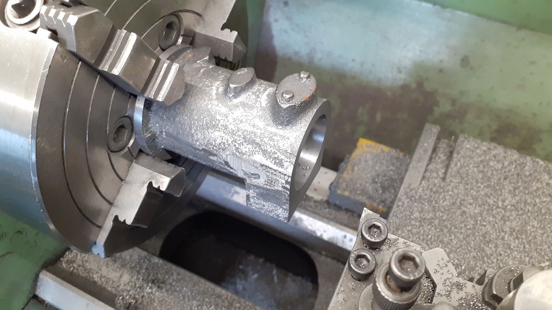
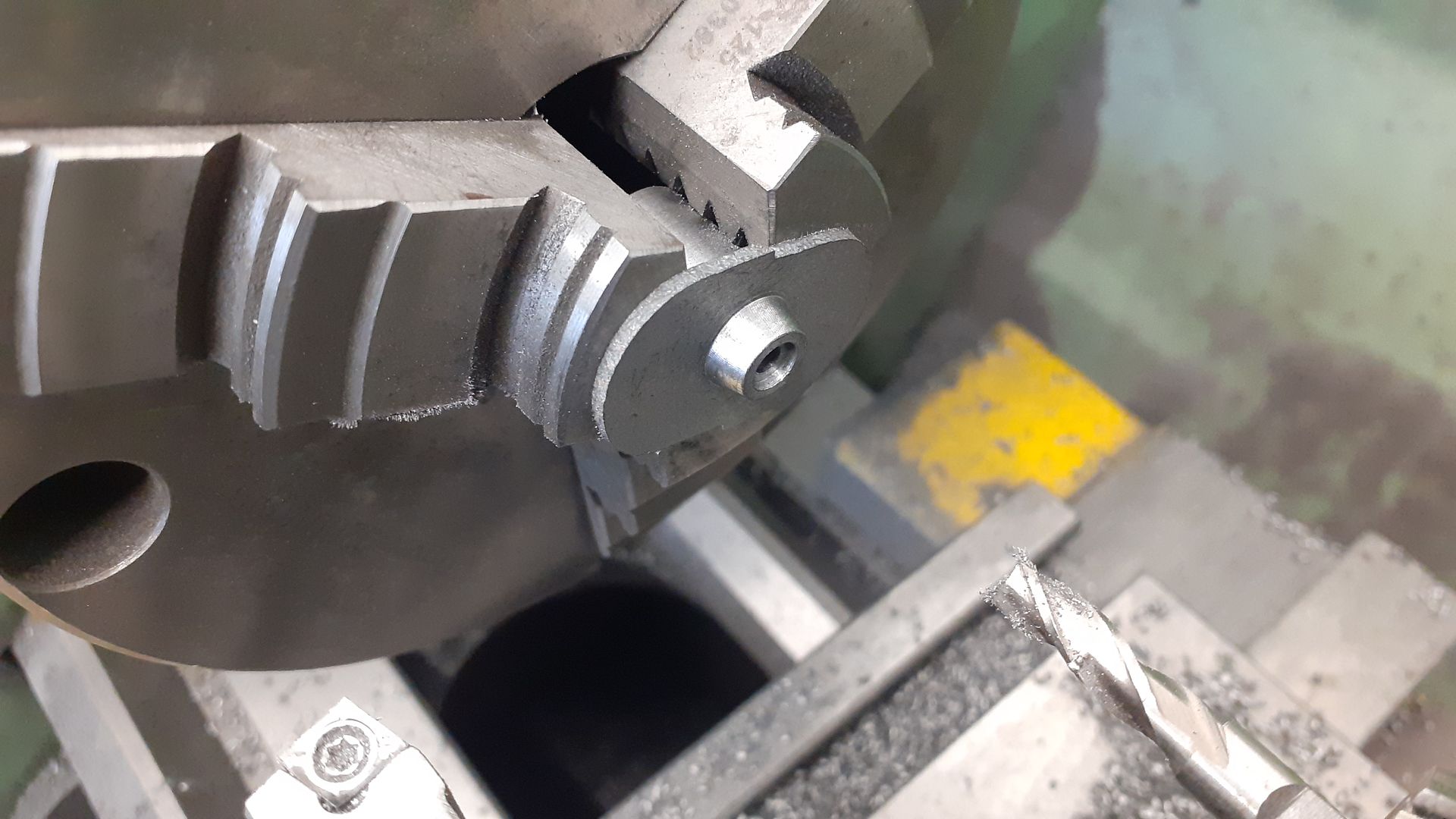
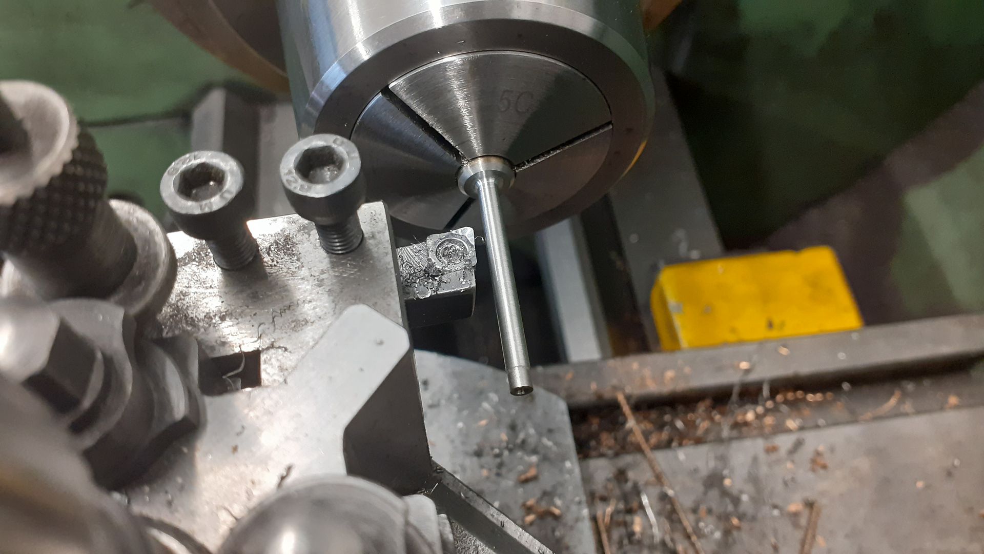
The casting was then flipped around and the head end faced back, again getting as close to the boss as possible, in this shot 0.5mm has been left to be skimmed off after the liner has been fitted.

20240302_090652.jpg


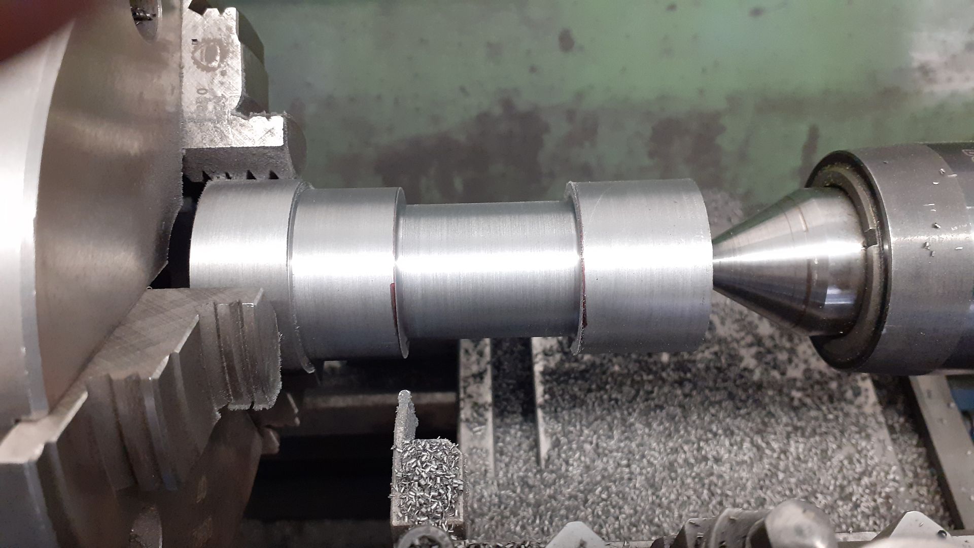
One end of some cast iron bar for the liner was cleaned up and then held by that section to turn the OD and cut a waist that will become the water space. I used tailstock support while doing this.

20240307_141347.jpg


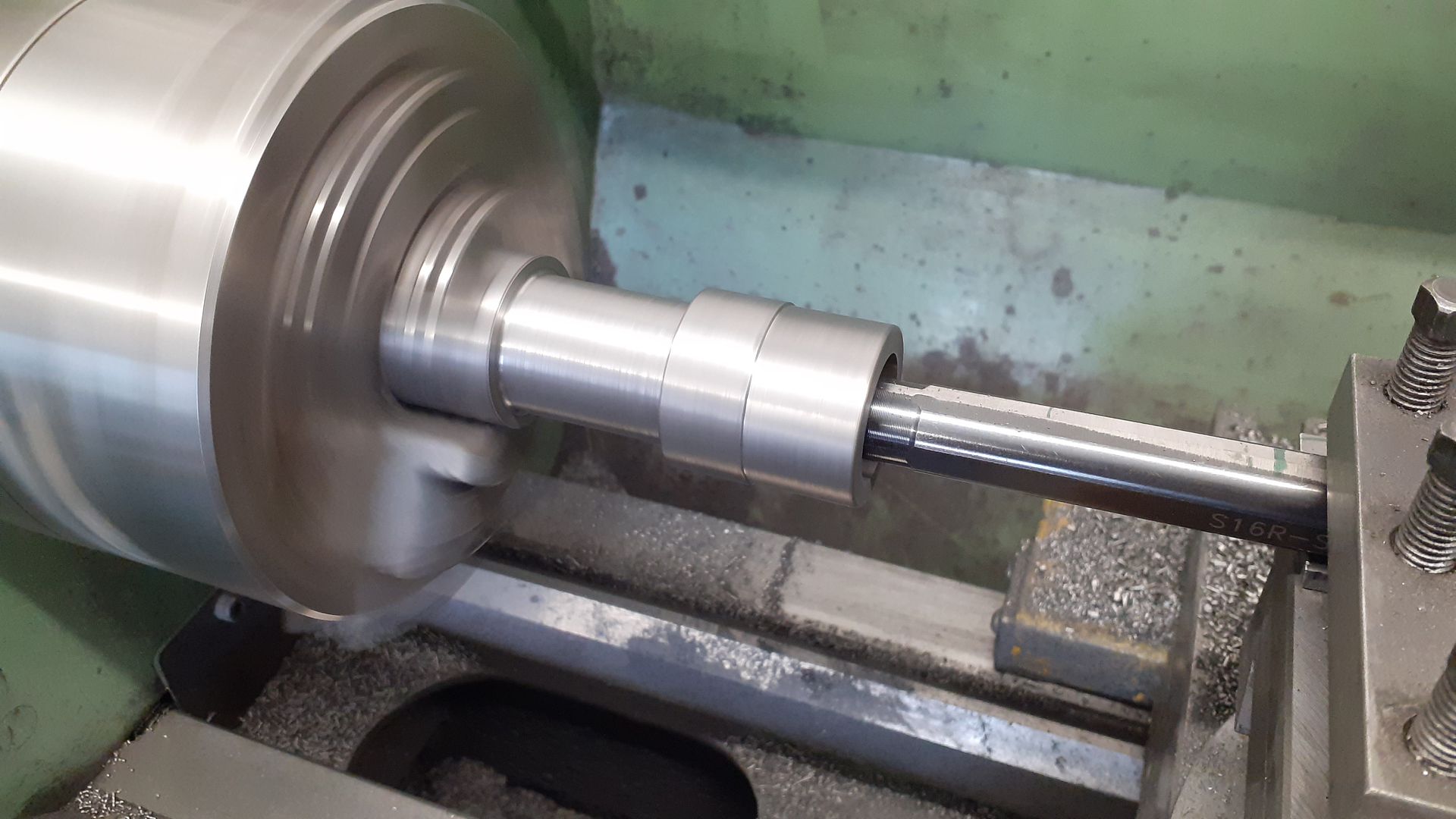
Gripping by the other end the chucking diameter was taken to it's final size and the cylinder drilled to 22mm and then bored to the final 24mm finished size after which it was loctited into the jacket with #648

20240307_151826.jpg


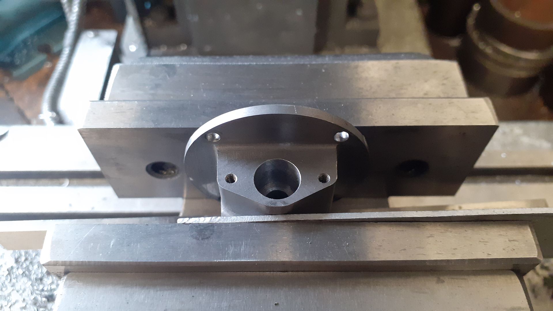
After a couple of days to make sure the loctite had set the 0.5mm was faced off the end of jacket and liner to give a true flat surface for the cylinder head to seal against. Then the 100mm vice was mounted lengthways on the mill table so that the assembly could be further machined. Firstly the exhaust block was milled to height and reamed to take the valve cage and it's two retaining stud holes drilled and tapped. A water inlet hole was also drilled and tapped and lastly at that setting one side of the exhaust block was milled flat to later receive the side shaft bracket.

20240309_082012.jpg


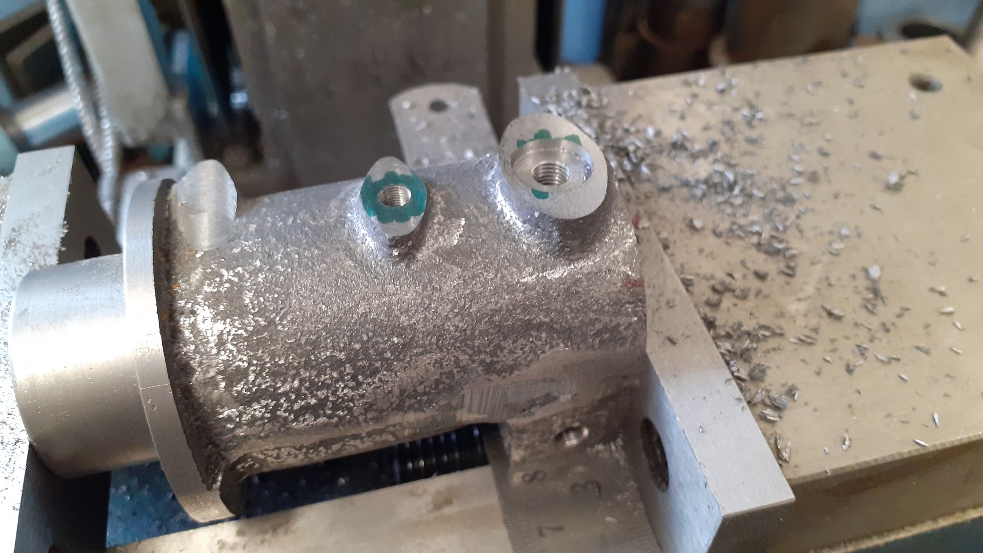
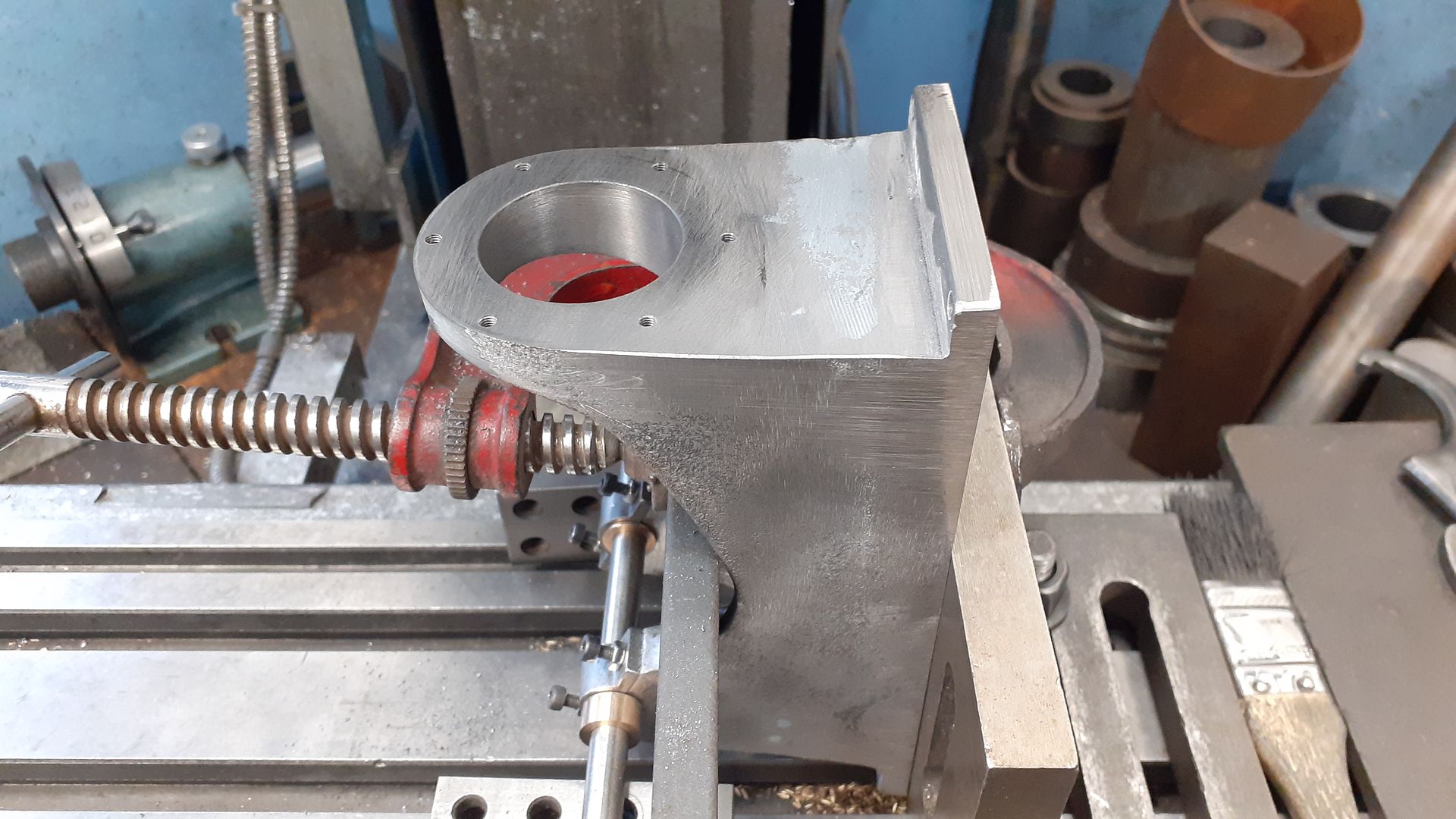
Turning the cylinder the other way up the tops of the various bosses were milled to their required heights, the central one tapped for the water connection and the one at the head end tapped and counterbored for a 1/4" x 32 Rimfire plug. The smaller one will get drilled to suit what oiling method I decide to eventually go for.

20240309_090102.jpg


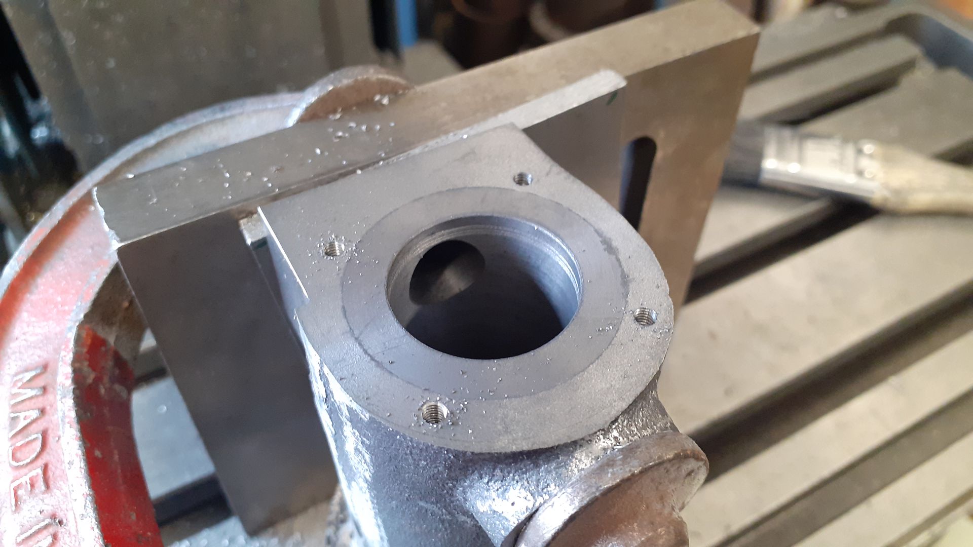
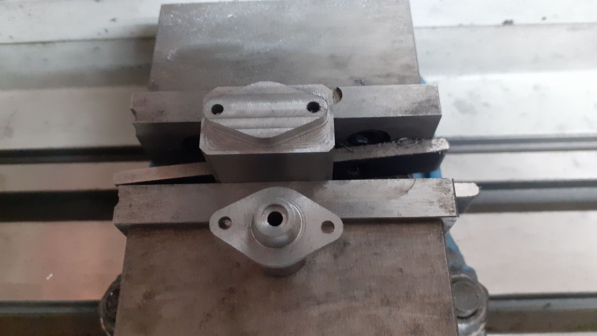
Lastly the two stud hole patterns were done on the flange and head ends

20240309_092452.jpg
 
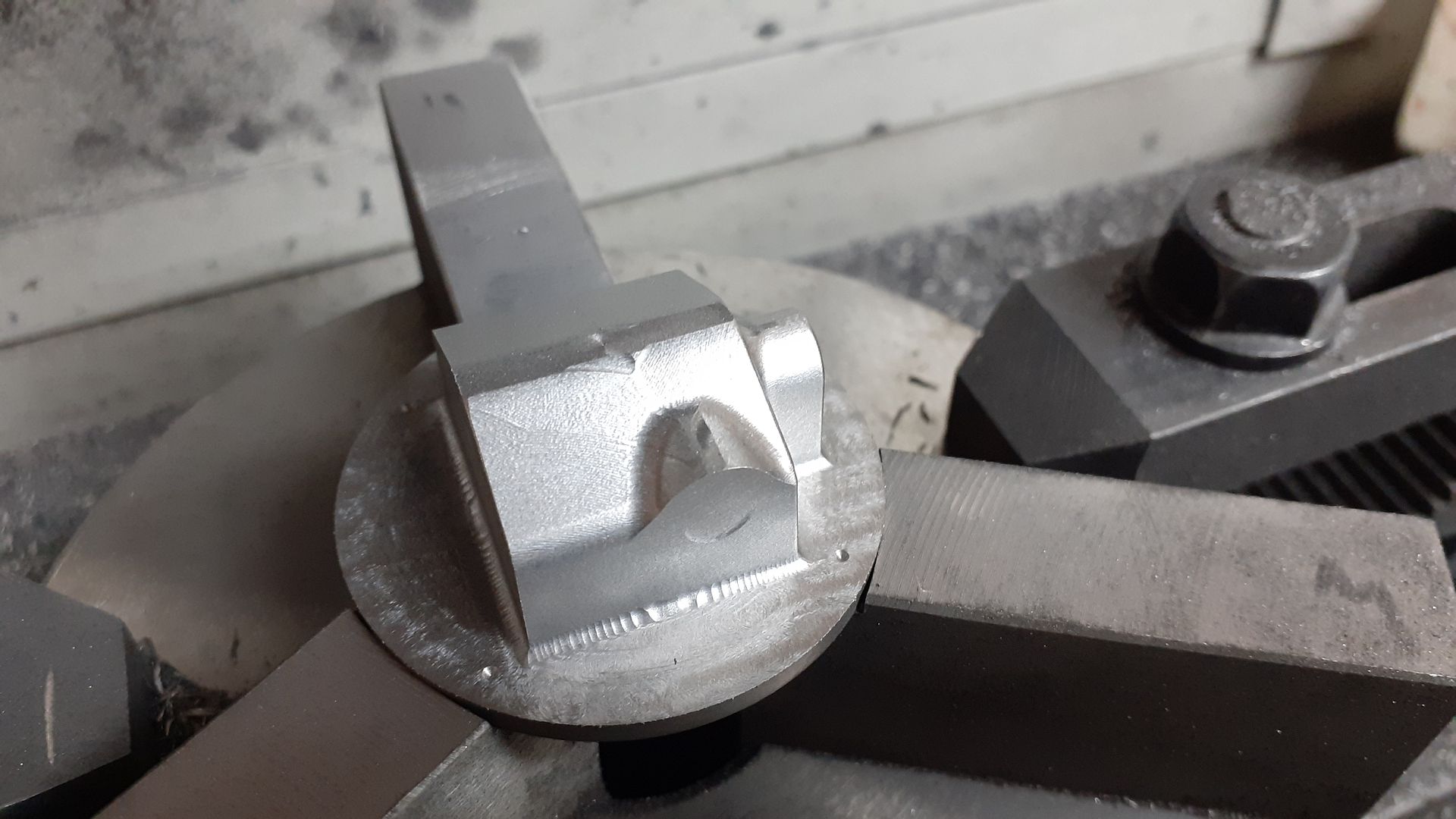
The head was drawn up as if it were a casting with draft angles and fillets. After turning the spigot that fits inside the cylinder I used that to hold the stock and let the CNC take the strain. The video shows the initial adaptive cuts which remove the majority of the material which were done with a 4mm 3-flute carbide cutter. After that I used a "scallop" path which steppes the cutter over 0.2mm per pass as it travels in three axis at the same time, this was done with a 4mm 4-flute cutter with 1mm corner radius (convex) as I wanted the small internal fillets that this would leave.


Ljck4JWJPFo
20240301_122404.jpg


It was then back to the manual mill to complete the inlet valve pocket, seat and guide as well as drilling and tapping for a cover plate. A thread for the carb was also tapped in from the side M6 x0.75.

20240327_143157.jpg


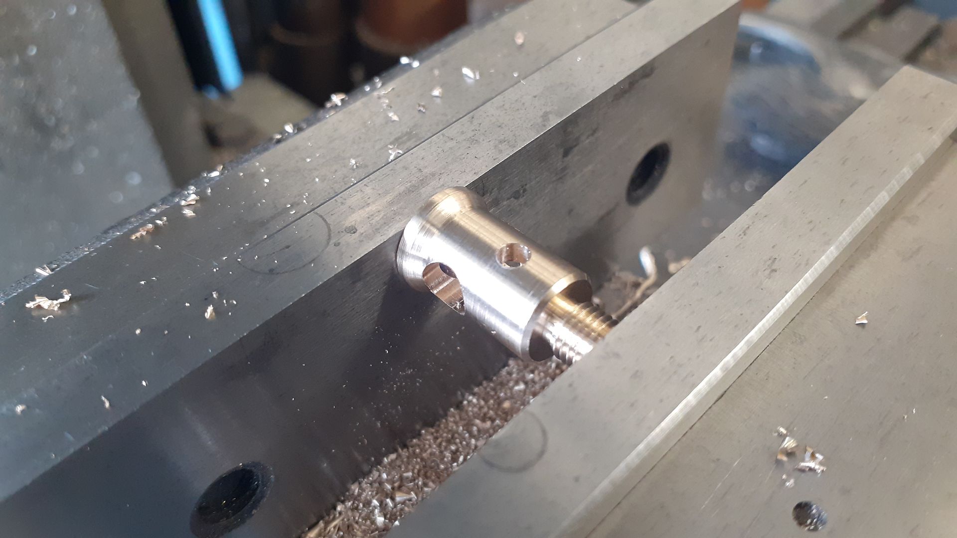
I had an old casting with oval section bars that was not going to get used for it's intended purpose so cut that up and used the material to turn the exhaust valve cage from.

20240310_083250.jpg


The other side had a small spigot to extend the length of the guide which was counterbored to locate the valve spring.

20240310_085722.jpg


Then used the CNC to shape the flange along with a similar shaped cover for the inlet valve

20240310_135652.jpg


Valves were cut from 303 Stainless using ctr support while turning the 3mm dia shanks. Then a CCGT insert with 0.8mm tip radius used to form a fillet behind the head and cut the seat at 45deg with the topslide set over to that angle.

20240328_135928.jpg


The valves were cross drilled 1.0mm for some pins which were turned up along with some caps. Springs were sized from my collection by the tried and trusted squish between finger and thumb to see what feel right method.

20240421_133642.jpg
 
Last edited:
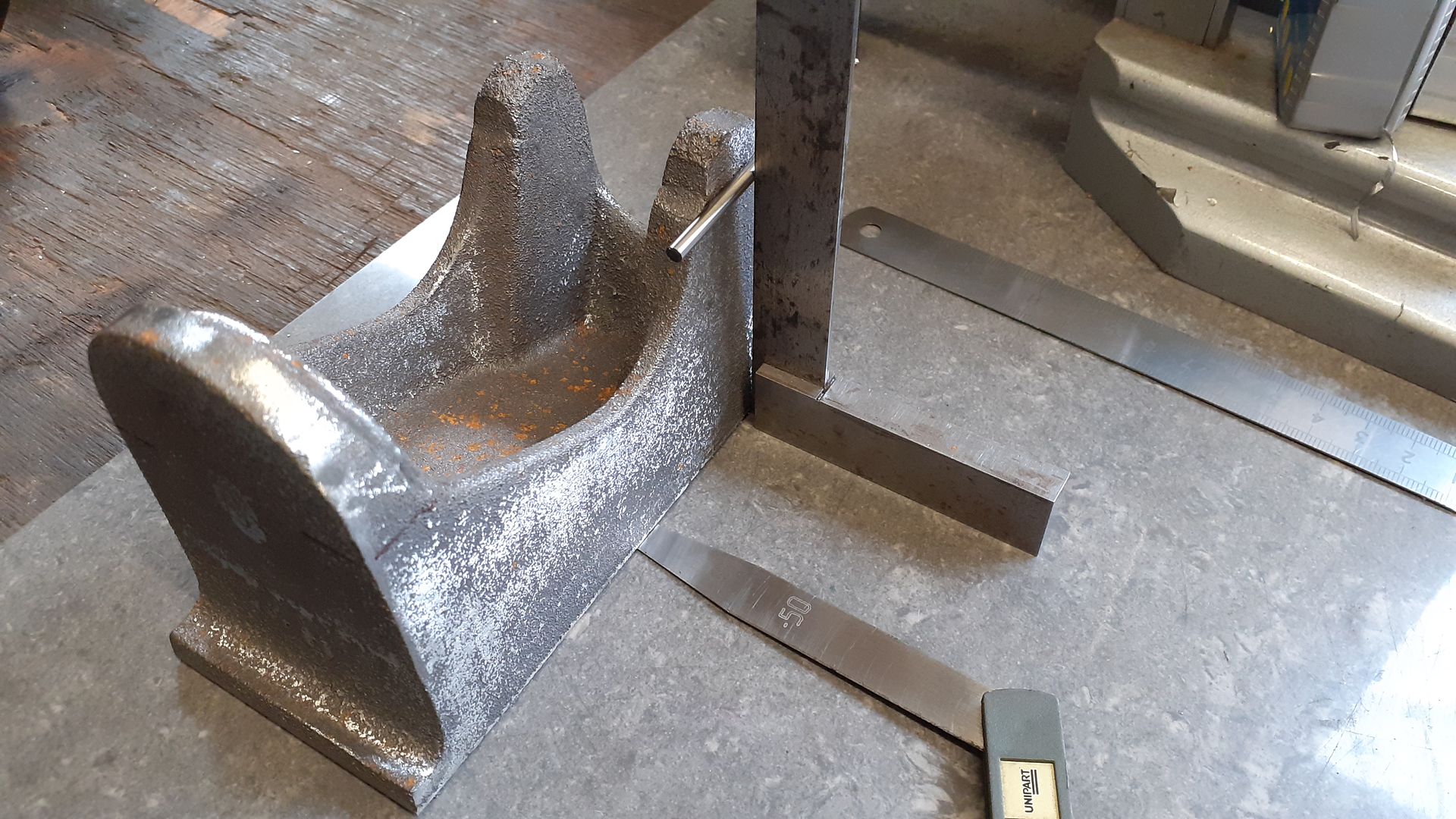
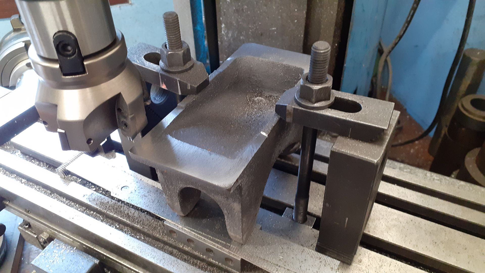
The engine frame casting was threated much the same way as the one for nattie was. After fettling I used some drill bits to gauge the angle of the sides while feeler gauges were slipped underneath until things were equal all round.

20240302_091431.jpg


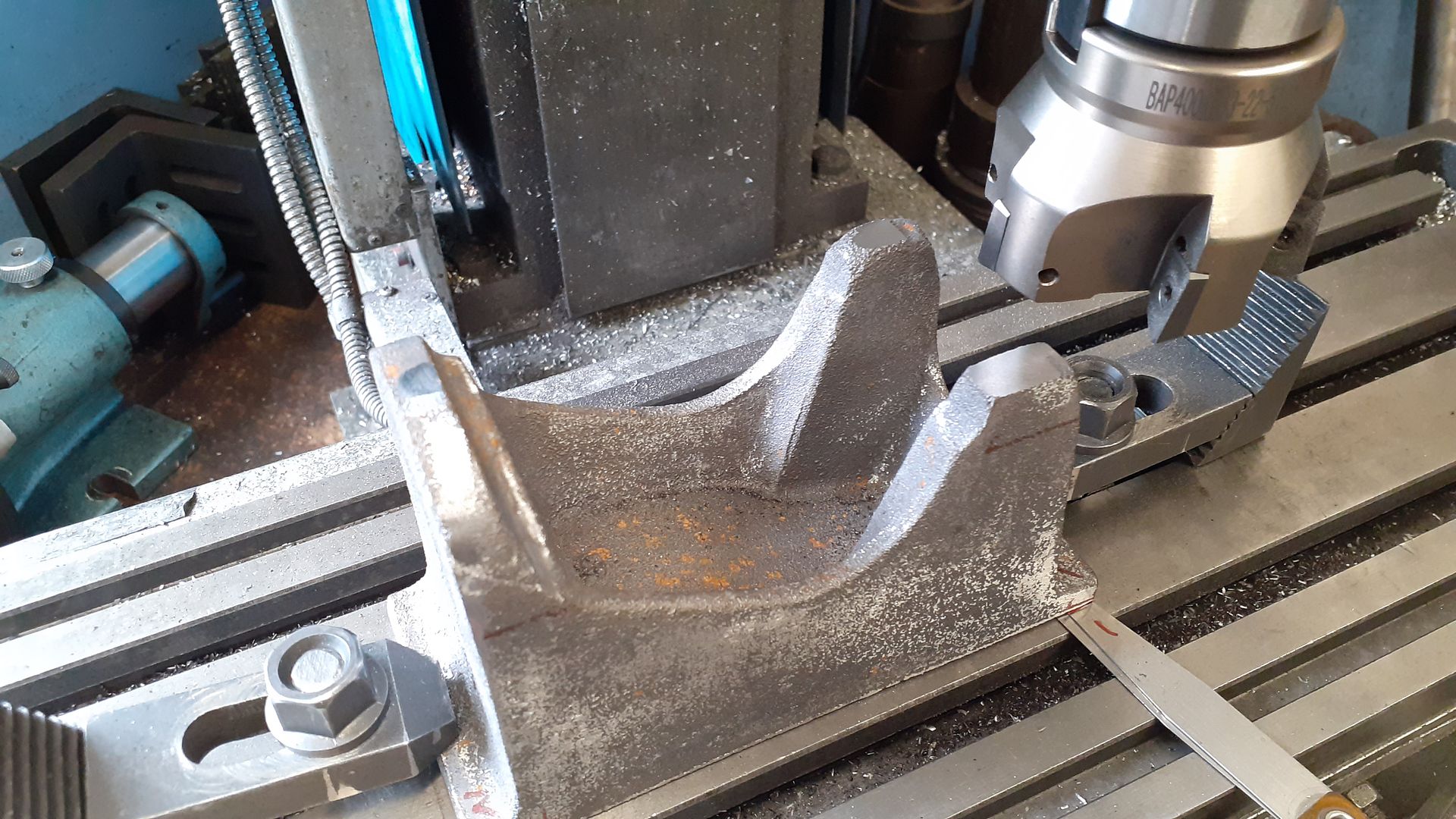
The casting along with the feeler gauges was transferred to the mill and a light skim taken off the top of the cylinder arch and also the two bearing caps noting how much lower the caps were than the arch.

20240302_092757.jpg


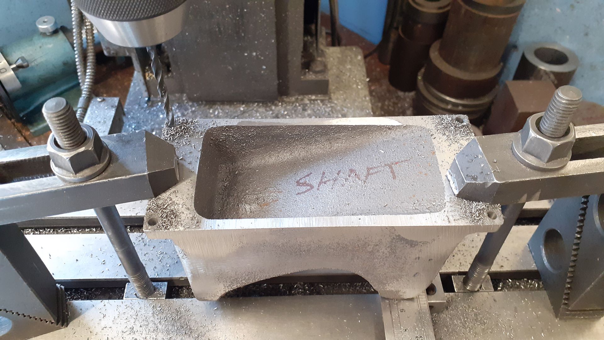
The casting could now be stood upside down with suitable height packing to have the bottom surface milled flat.

20240302_095039.jpg


A quick change of setup clocking the casting true along the X axis and the four mounting holes were drilled equally either side of ctr. I drilled these 3.9mm which was a tight fit on the M4 screws that will be used to hold it to a machining plate which saves having to dowel things if the casting needs to go back onto the plate at any time.

20240302_135411.jpg


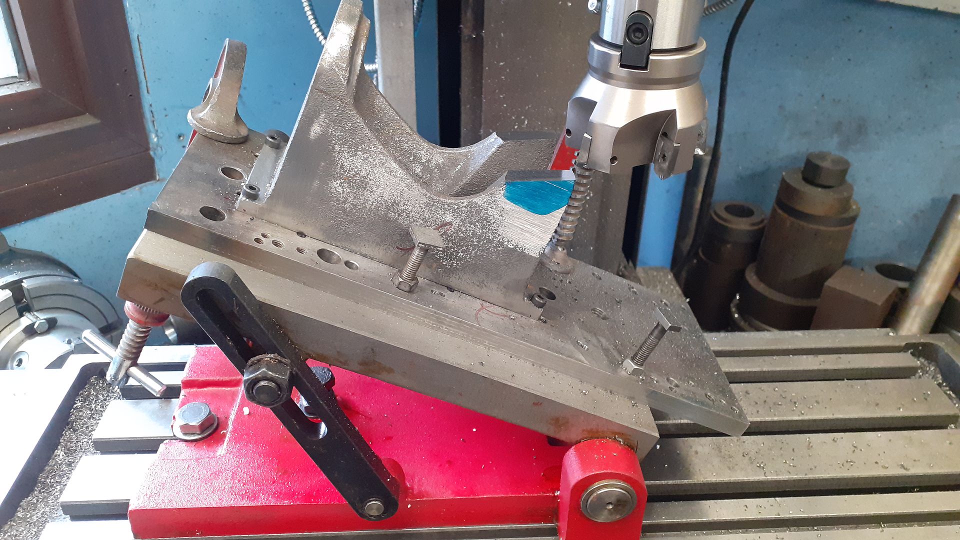
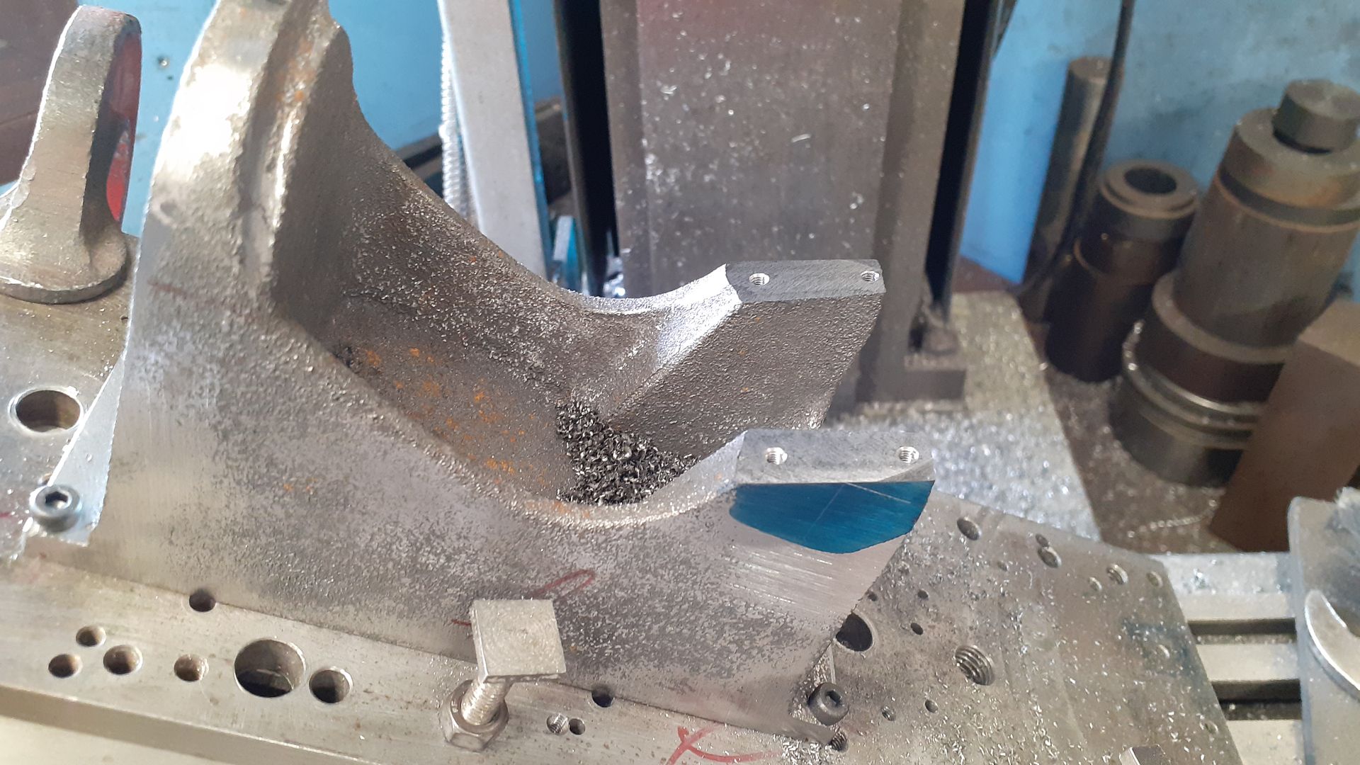
I then used an adjustable angle plate to set up the casting for machining off the cast bearing caps at 25deg.

20240303_090137.jpg


M3 holes were then drilled & tapped to hold on new bearing caps

20240303_092635.jpg


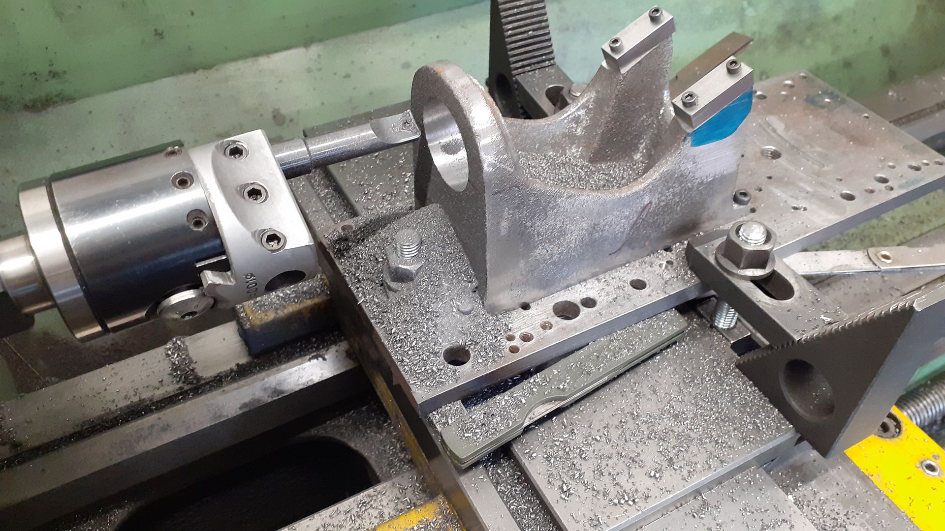
Over to the lathe with the fixture plate packed up to bring the engine ctr line upto spindle height a boring head was used to bore out the hole for the cylinder spigot.

20240303_140353.jpg


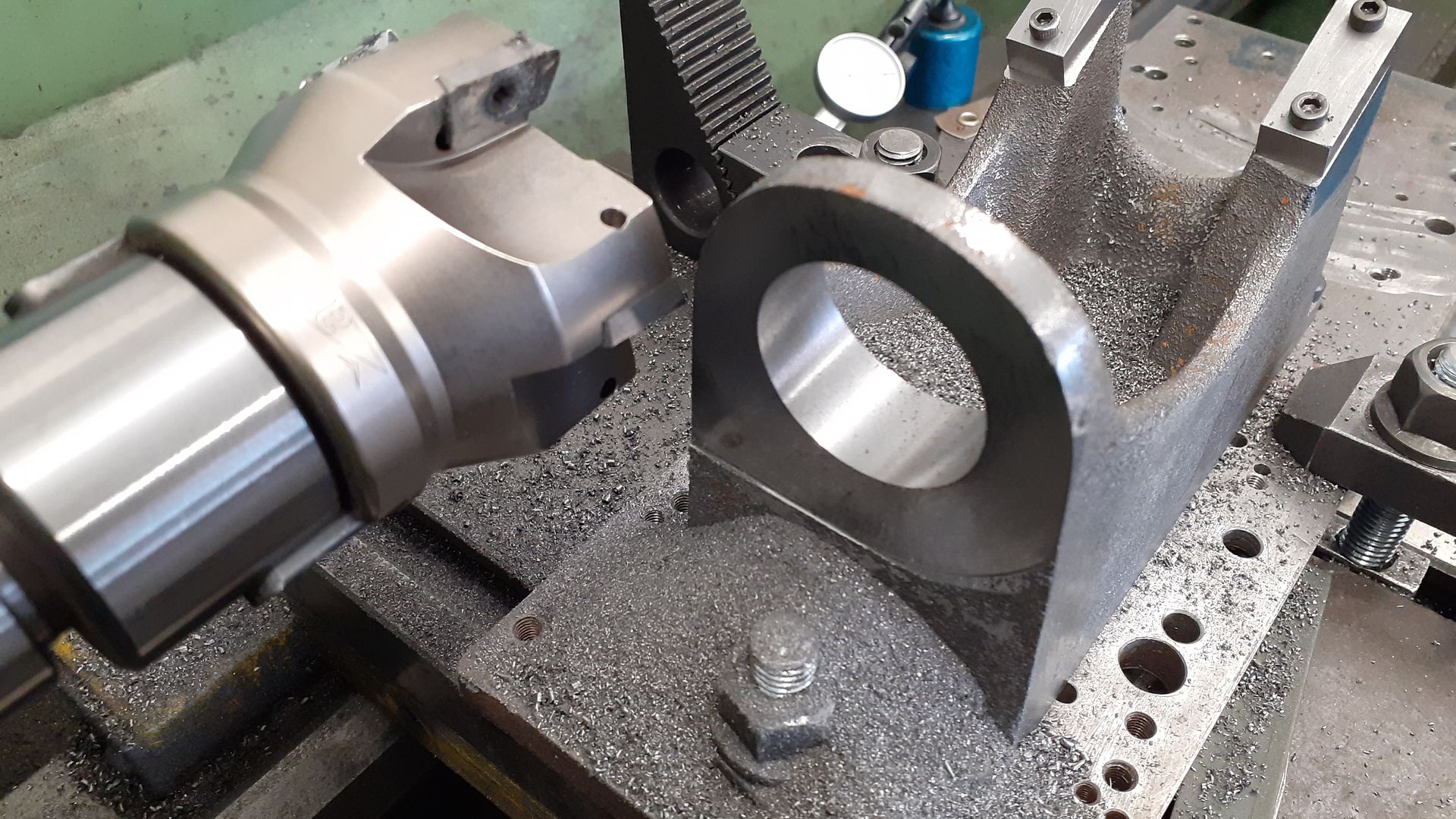
Then a facemill to square off the cylinder mounting surface square and true to the hole

20240303_143107.jpg


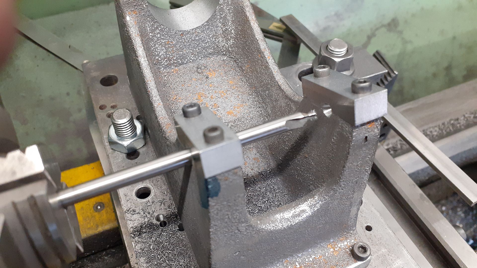
Swinging the fixture plate through 90deg the bearing housing closest to the chuck was spot drilled, drilled 4.8mm and then reamed 5mm and that hole then used to help guide the long reach ctr drill to locate the hole on the opposite side.

20240303_150040.jpg


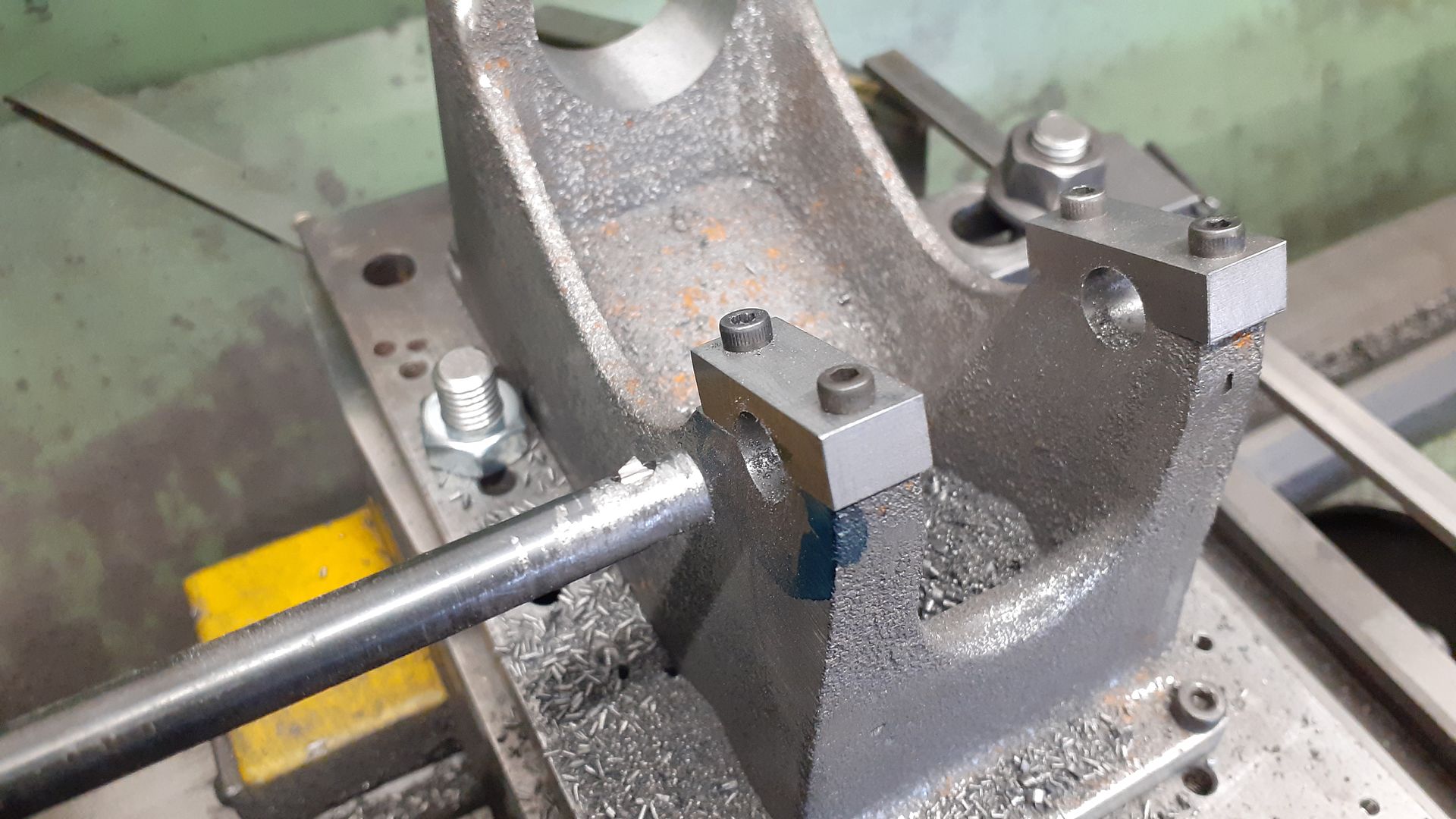
The two holes were then drilled out to 10mm, and then bored to approx 11.75 to make sure there was no wandering of the drilled holes as they both started on sloping surfaces.

20240303_151516.jpg


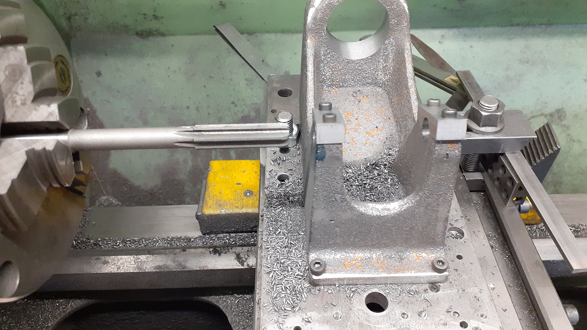
A 12mm machine reamer was then used to finish the holes

20240303_151808.jpg


20240302_135411.jpg
 
The remaining jobs on the engine frame were to drill and tap for some studs to hold the cylinder to the frame, this was a bit tight as room for nuts had been left off of the original Nattie design plus as I wanted the cylinder flange to be a smaller radius than the arched top of the frame as per original I had to reduce the flange diameter which eft even less room for the nuts.

20240323_135431.jpg


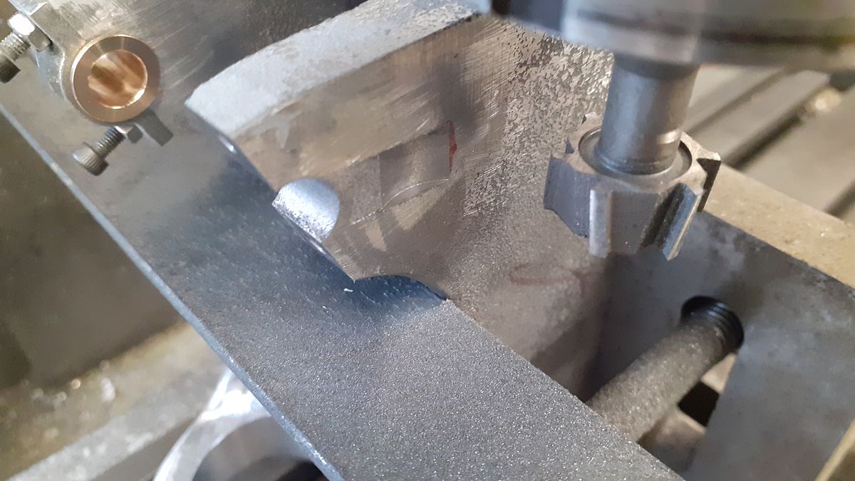
I also wanted to keep the flywheels as close as possible to the bearings so used a tee slot cutter to scallop out a space so that the side shaft gear would fit closer to the frame without hitting it.

20240317_084531.jpg


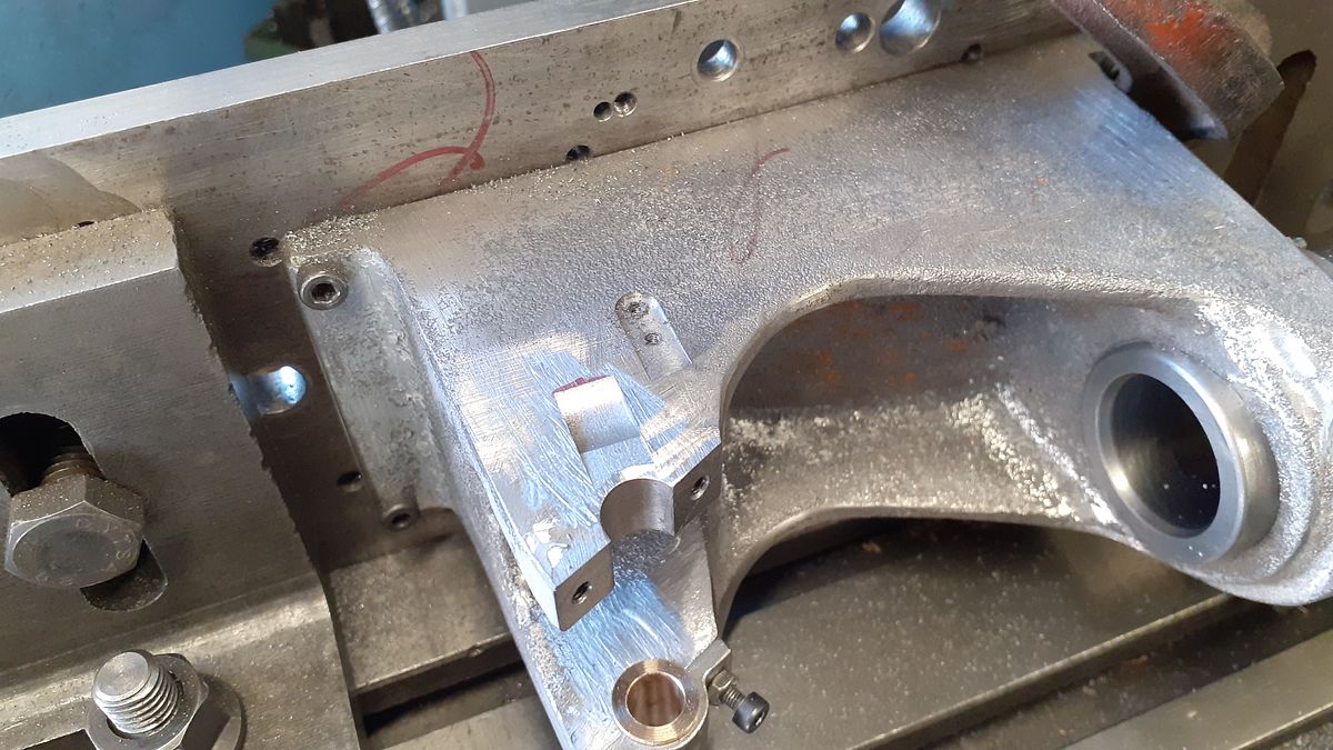
I also milled some vertical pockets to take the side shaft bearing support bracket and later added another for the ignition timing bracket. You can see the scalloped out recess better in this photo too.

20240323_144000.jpg


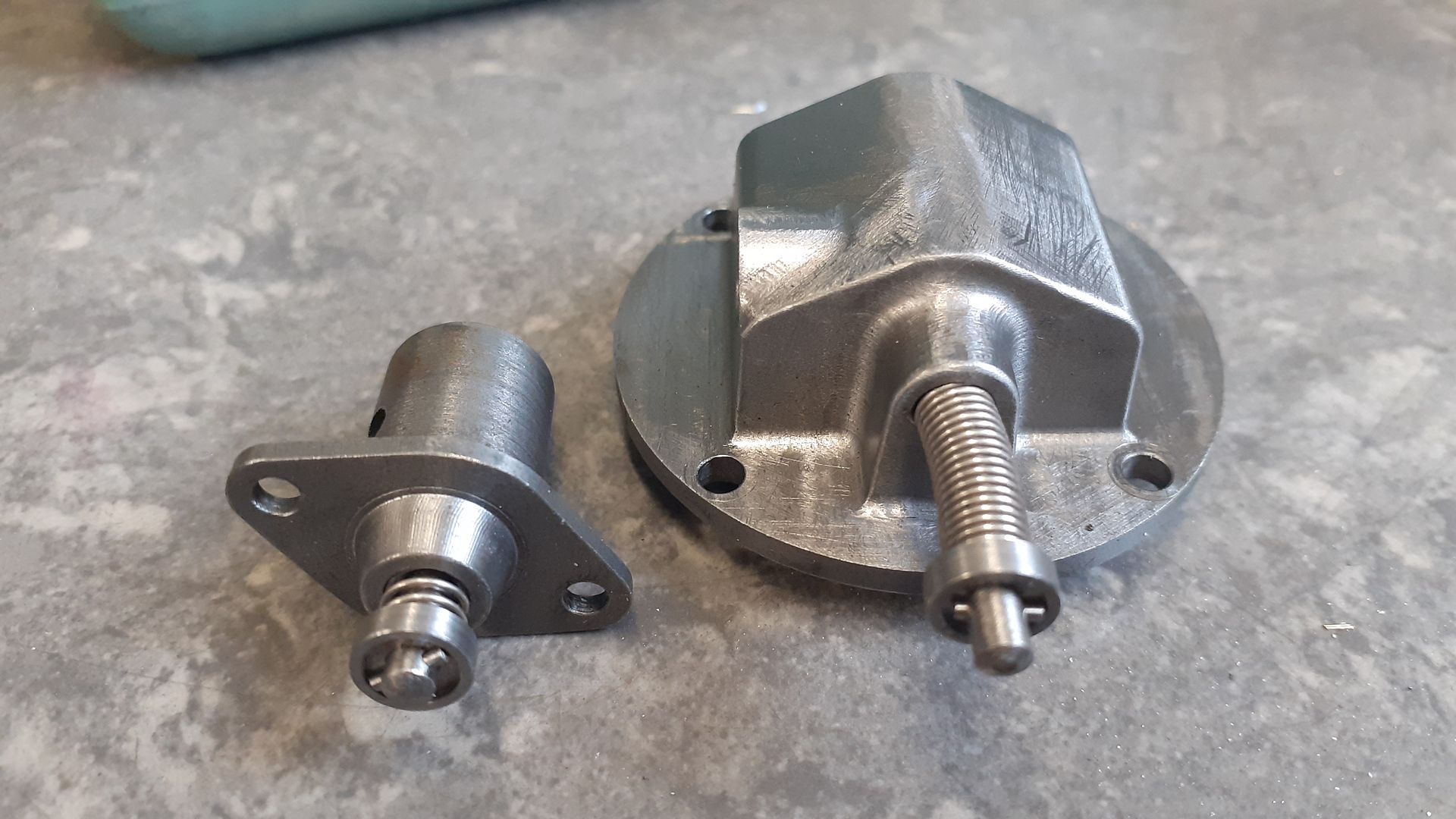
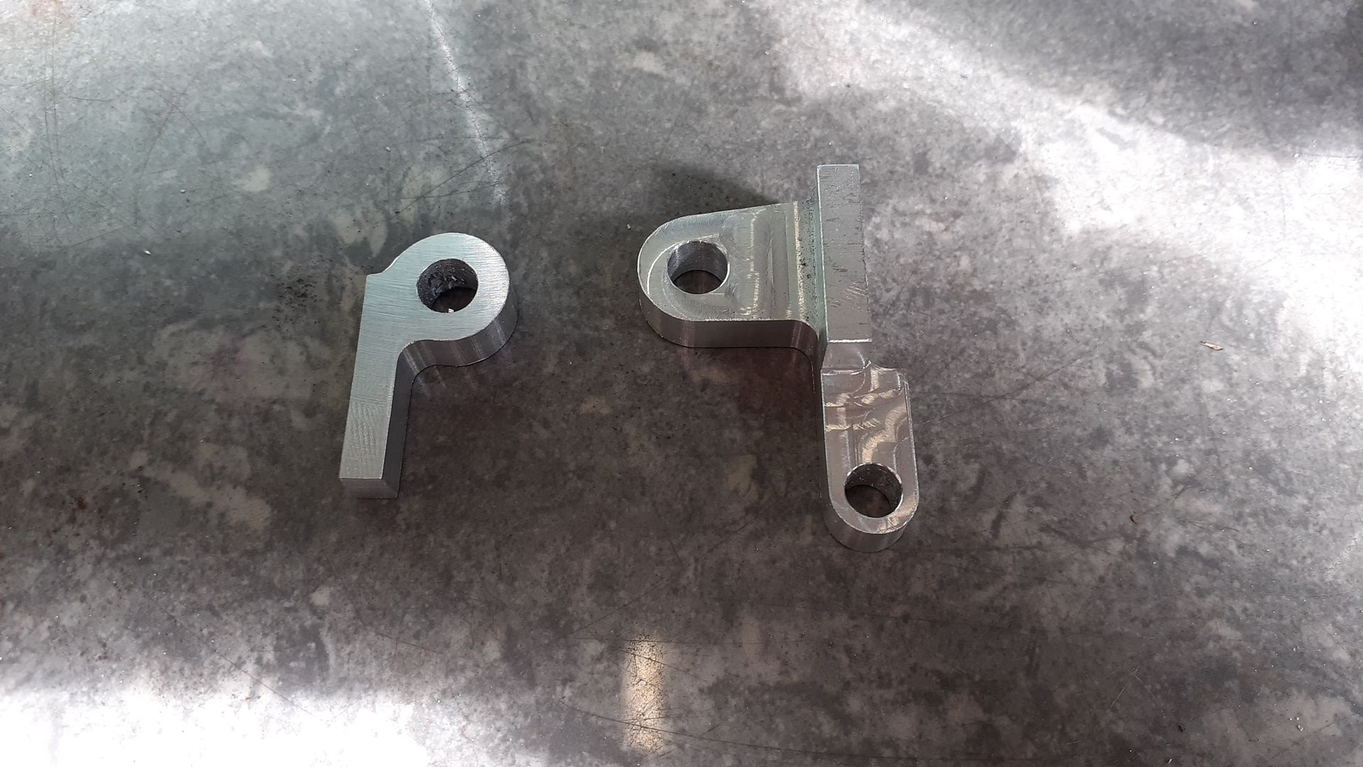
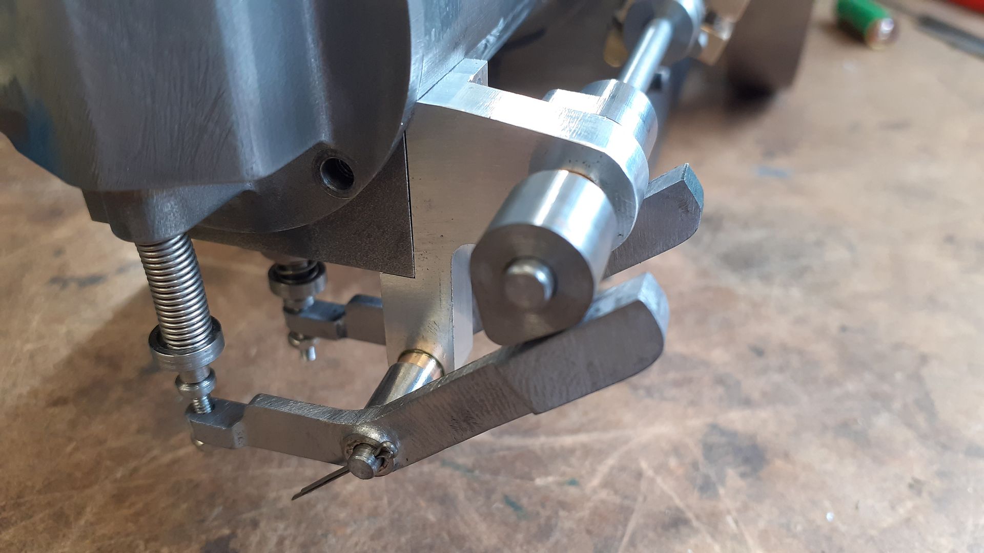
The side rod brackets are shown below, the one on the left fits at the gear end in the pocket shown in the previous photo. The one on the right fits to the head end of the cylinder and also provides a pivot for the rocker arms. After shaping on the CNC the waste holding material was milled away and bronze bushes loctited into the holes.

20240324_135735.jpg


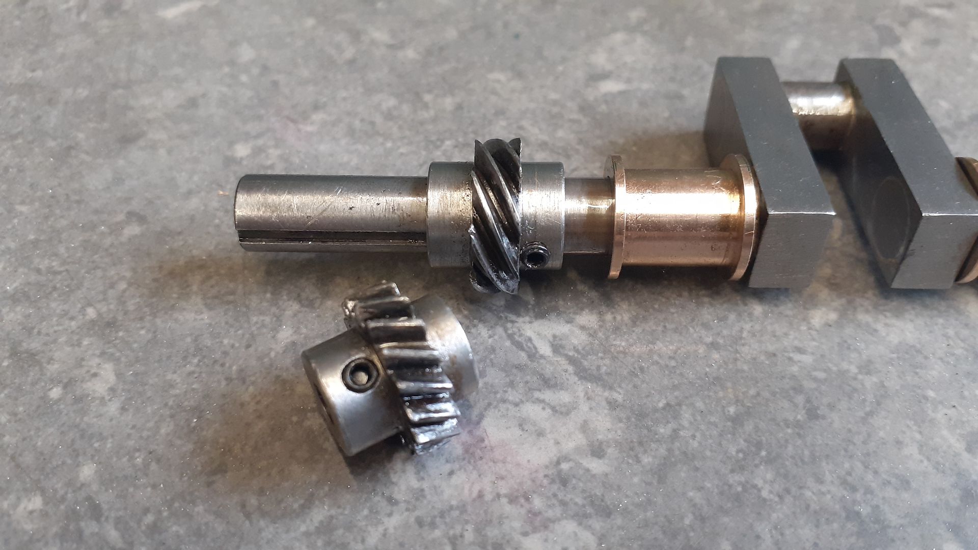
Graham had provided the gears which were from a batch he had made by HPC and although still in their original blister packs had managed to aquire that special brown coating so the first job was to remove as much of that as possible with small wire brushes. As supplied the holes were too big and to add to the problem they were sized in fractional Bananas so I silver soldered them onto the ends of some steel rod before re-machining to suit my needs.

20240421_133523.jpg


These gears are 1:2 ratio but due to the different helix angles on each gear are both the same diameter which is ideal for side shaft engines as gears with 45/45 angles end up with a large gear on the side shaft resulting in everything having to be spaced a long way off the side of the engine to accomodate the large gear.
 
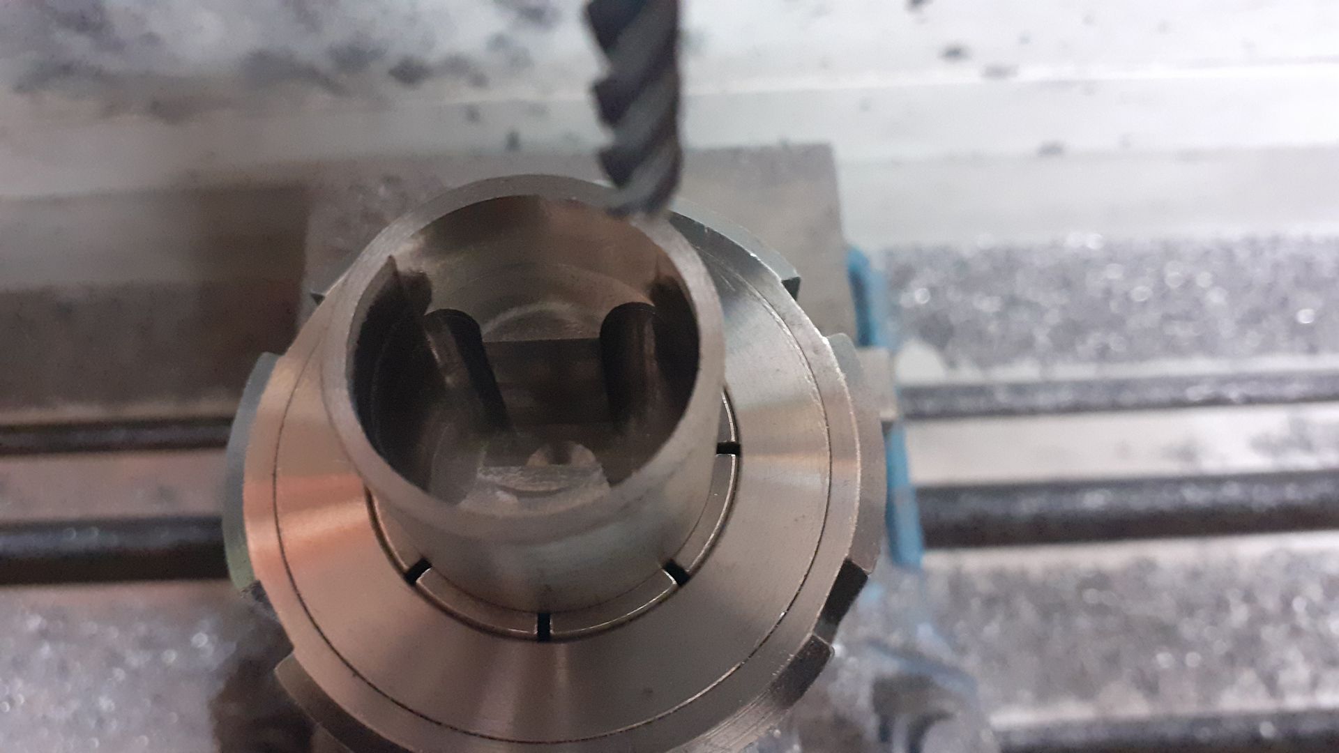
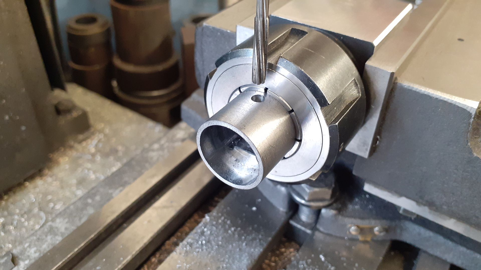
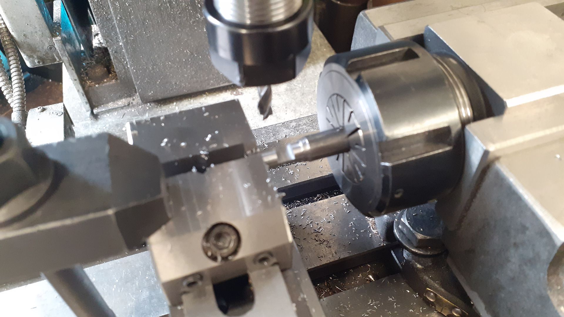
The piston was turned from some 25mm cast iron bar using the cylinder to gauge it's diameter. Then into an ER32 Block to first have the dog bone shaped recess cut followed by drilling and reaming for the gudgeon pin, the ER block allows the work to be indexed to easily get the hole at 90deg to the vertical set up and passing through at the right angle.

20240321_151633.jpg


20240322_135540.jpg


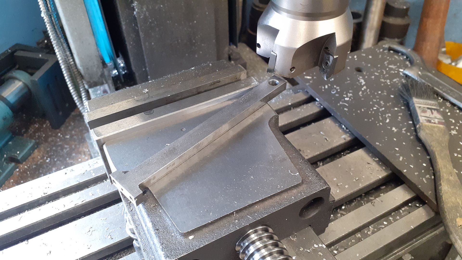
A piece of 6mm flat bar was squared up for the con rod and the various holes added before using a facemill to remove the majority of the waste material to leave a basic "T" shape.

20240329_112254.jpg


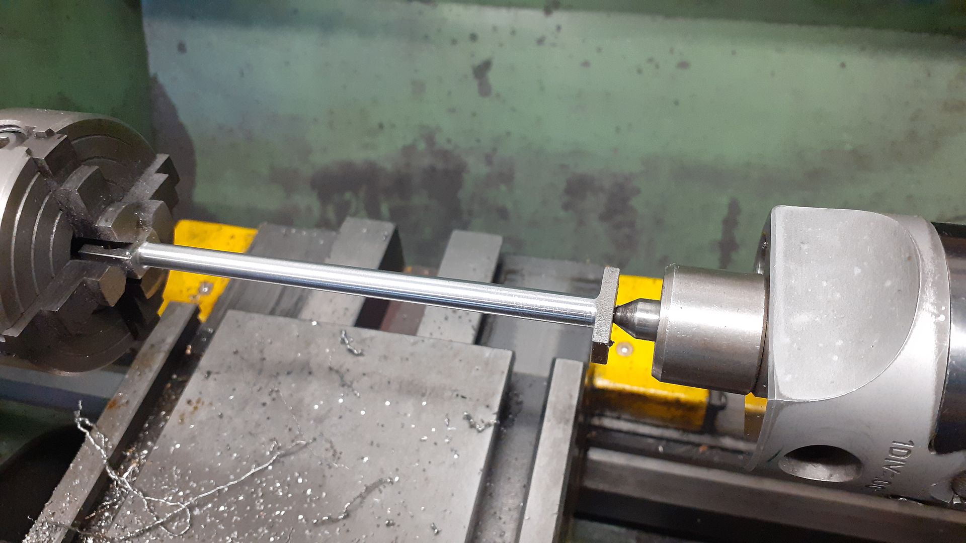
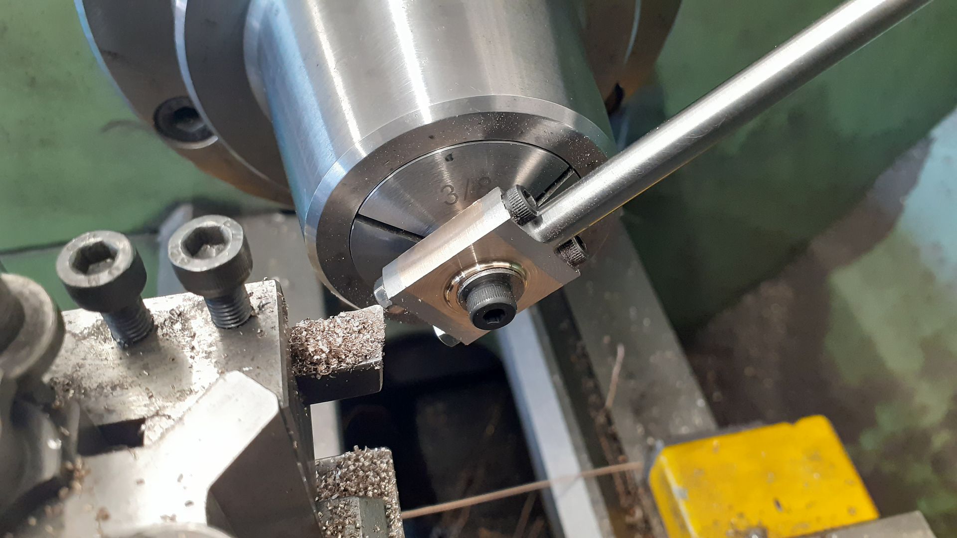
Using a boring head a tailstock ctr was set to allow the tapered rod to be turned with a 1mm radius grooving tool.

20240329_121334.jpg


The big end brasses and cap were the usual fare of machining to size, drilling for the M3 studs and then reaming 8mm for the crank pin. The whole lot was then assembled and the sides of the bearings & cap turned to leave a raised area in the middle.

20240330_091444.jpg


The two rocker arms were milled from 4mm flat bar and then drilled before soldering on some longer pivot bosses

20240414_093023.jpg


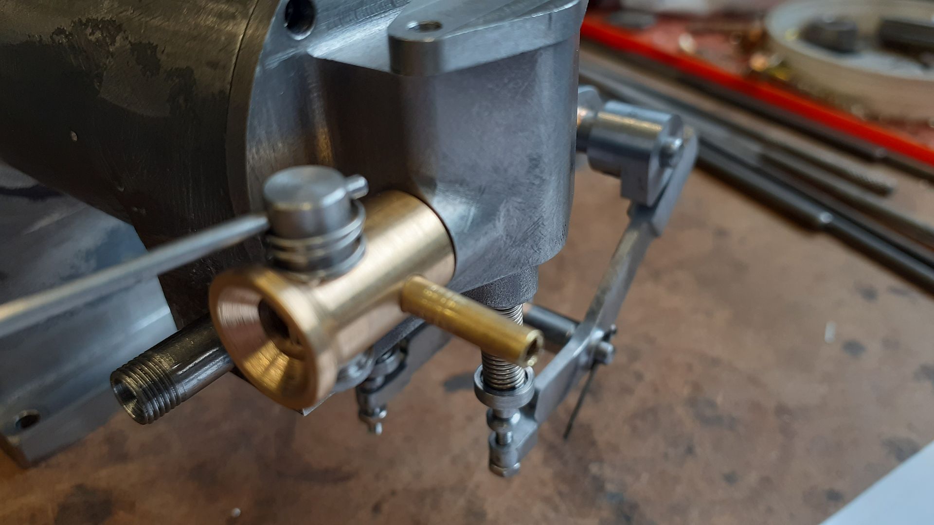
I had decided to use a metricated version of Nick Rowland's (RMC Engines) vapour tank and carb, the body of which was turned from some brass bar before being cross drilled and reamed for the butterfly valve and then a smaller hole for the fuel connection at 90deg to that.

20240406_091357.jpg


The valve was milled from either side to leave a thin section that became the flap of the butterfly, as itis only 0.5mm thick a small toolmakers vice was used to hold the otherwise unsupported end.

20240406_093605.jpg


A piece of rod and a short spring completed the carb

20240414_093116.jpg


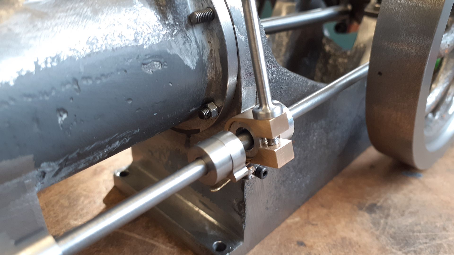
I used my usual S/S ignition and to trip that machined up a simple "cam" to fit on the side shaft. This makes contact with a thin piece of brass held between Corian insulators on an adjustable bracket which allows the ignition timing to be advanced or retarded.

20240414_093052_6khbULPhQ8sraRAFCRpGKx.jpg
 
It was at about this point of the construction that questions were being asked about whether soemones engine that did nor run had any compression. I suggested a simple test to show if there was any compression can be done without the need for a compression tester, etc simply by flicking the flywheel and seeing if it will bounce back unde compression. This is how Gassie was bouncing, I'm only rotating the flywheel clockwise - it is bouncing back by itself.


Not too bad considering the piston ring has not been fitted, no head gasket, no seals to the inlet or exhaust valve cages and not only were the valve just sitting in their holes without springs I'd put them in the wrong way round so they were not even on the seats they had been quickly ground in on.

With enough parts completed it was time for a test run. Much the same as the bump test with no gaskets, seals or piston ring but the valves are in the right holes and have their springs fitted. No fancy timing wheels just rotated the crankshaft by hand and set the cams where I felt looked right. After a small adjustment to the ignition timing off she went, not bad for a true prototype rather than a redraw.


It was then just a case of doing the last odd items such as adding the main bearing oil pots and making up some studs to replace the temporary cap heads that I tend to use during construction. I could not bring myself to paint it a dark green so went with something a bit brighter - Mustard Yellow.Oh and still no piston ring, though it does have a smear of instant gasket to seal the head.

 
Great looking engine, and great running engine too !

You make it look quite easy, but I know it is not.
Attention to small details is what I think makes for a good running engine.

Very nice work.

Edit:
I like the yellow.
A light shade of orange I think would also look good.
.
 
Thanks, I've got a pumpkin sort of orange ready to go onto another engine that is almost complete which is quite close to the original colour.
 
One area in model building where I don't necessarily adhere to the original is paint color.
The Soule Speedy Twin was Ford blue I think, and there is no way I am putting a Ford color on anything.

The green twin steam engine apparently was originally gray, and painted green, perhaps by Prestons.

I admire the powder coats, but they don't seem natural since they tend to gloss over the sand imprint in the cast metal parts.

I see a lot of gray and green in old engines, but that starts to get old after you see it on the 100,000 th engines.
Quite a few red engines, but I am not that keen on red either, although it does look nice.

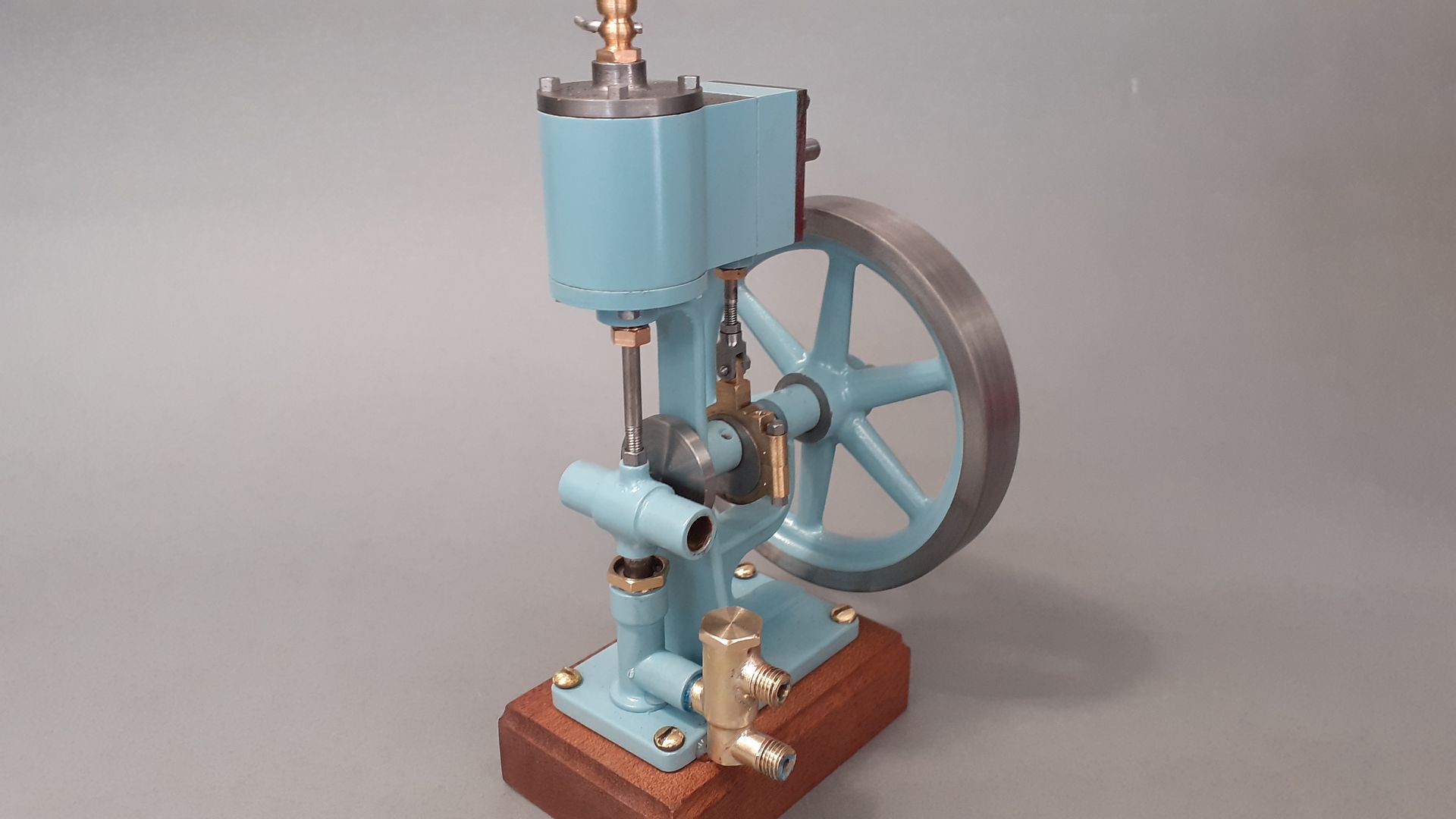
I like light blue, and a lot of non-primary colors.
The basic primary colors get a bit boring.

I like a blue/gray mix on the lighter side.

Cherry Hill was in my opinion the master of color schemes/painting, and I would assume those colors may not be original.
I prefer Cherry Hills colors to the original colors, if they do vary.

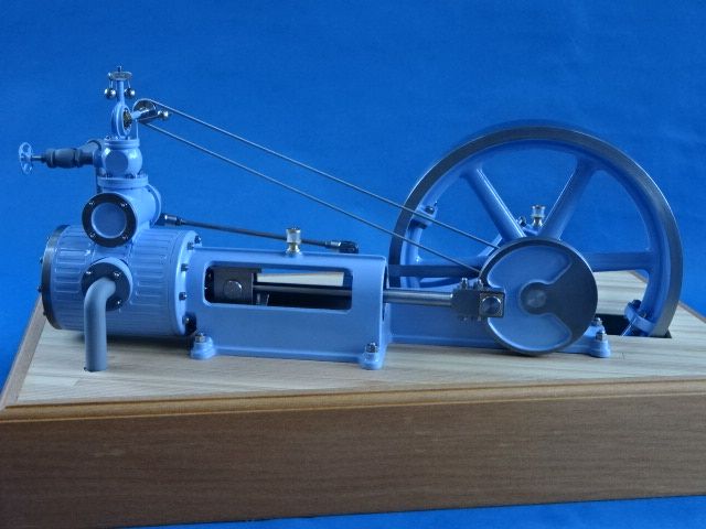
This engine at Tannihill has an interesting paint scheme.
Most likely not original, but looks nice.


r_150908.jpg
 

Latest posts

Back
Top