Gab ends / Sliding keeps - Help, please!

Home Model Engine Machinist Forum

Help Support Home Model Engine Machinist Forum:

This site may earn a commission from merchant affiliate links, including eBay, Amazon, and others.

Rivergypsy

Well-Known Member
Joined
Oct 15, 2010
Messages
432
Reaction score
222
I've got a bit of a problem on my entablature engine at the moment, so I though I'd try and tap into the wealth of knowledge out there...

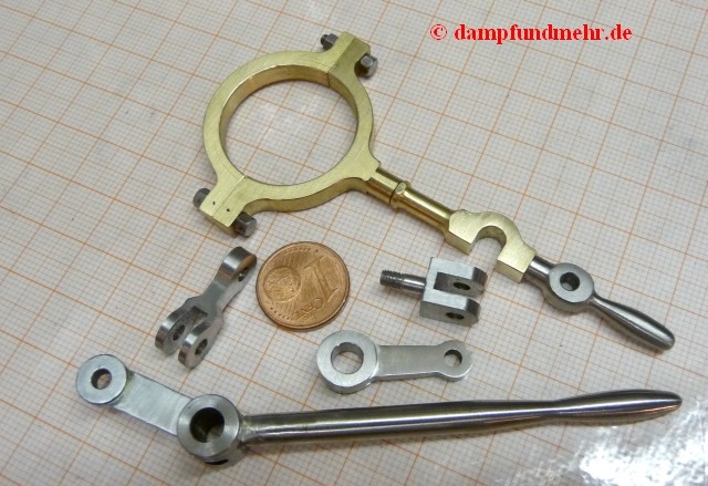
I've currently in the process of working out what's happening around the pump and valve links, and I keep running into the term 'gab ends with sliding keeps'. Now's I've found older gab ends for disengaging valve gear of horizontal engines, but I can't find anything that seems to suit what we have here.

I've attached images of the links themselves, the text from the write-up, and an image I found for horizontal gab ends, so if anybody gets the urge to take a look and throw any ideas or pictures up, it would be very much appreciated, please! I've lost count of the number of copies of the enlargement that I've been sketching on so far, lol
hide.gif


Entablature Links - 01.jpg


Gab - 01.JPG


Gab - 02.JPG


Appletons Vol1 - P687.jpg
 
I've always taken it to mean an open slot, in our cases a "U" shape so the rod can be slipped off the pivot. As you say quite often seen on the eccentric rods of horizontal engines.

Sounds like the sliding keep is just some form of plate that closes the gab to keep it engaged and the plate is retained with a small pin.
 
I would think its a similar arrangement to the rod below where by lifting the lever will stop the eccentric driving the pump.

As you don't want the valve gear disengaging by itself some form of plate could easily be fitted to teh bottom of the U to keep the rod on the pin.

P1010045.jpg


I'm almost certain that the ME Beam has some form of keep buit can't find a decent picture to confirm
 
Hi Jason,

Thanks for your reply. I'd pondered this arrangement, but once the keep is released, and with the angle of especially the feed pump rod, what stops it dropping back into the slot again?
Btw, where are you in the uk? I'm in Cambs if you're local..,

Many thanks
Dave
 
I suppose the keep could be slid back to stop the gab dropping over the pivot.

I'm on the Kent/Surrey borders near J6 of M25.
 
hi
here are my views on this puzzle. I read the paper, yes not much clues, apart the way to make your own wood screws !
as said Jason, the pivot is locked in place by a sliding plate. but in addition as said in the text, the slide may also prevent the pin to slip into gear accidentally.
a small attached drawing, and I hope this helps.
to quote the Gentry paper "connecting rod and gab ends links are works of modelling art in themselves..."
cheers

IMG_4878r.jpg


IMG_4879r.jpg
 
Jason - many thanks for your reply, that does make sense. I'm wondering if I've been going around in circles on this, and not thinking outside of the box a bit more.

I have an outlaw in Surrey, so if you fancy a good gossip next time we're there...

Gedeon - top thoughts, thanks, and sketches too! :D many thanks too for the thought you've put in to this. Your idea of the slot with the closable pocket seems good. I've not seen it's like before, but it fits with what is visible...time for some more sketching and the SW work...

Many, many thanks to you both!!
 
Ok, well I've done a bit of sketching in this area now, and it slowly seems to be coming together, so again many thanks for all the help!

Another question though - the side links that connect the top of the valve rod to the lever and the eccentric rod - has anybody got any infomation or pics as to how they are assembled, please? I can see a pair of split bearings in each, with I assume a steel centre between them, and then a wedge or bolt through that. What I'm headscratching is how all these get assembled into the strap...

Any help gratefully recieved!

Capture.jpg
 
As drawn, this type of joint require a gib and cotter inserted into a slot in the strap and the central part, which grip part together. Obviously the central part must be split in any way to be able to tighten the slit bearings on both sides, this is not clear in the original drawings. Each part of the joint bears a small recess which fits and holds it into the strap.
I did a similar joint on 3 engines, but only single ended...too easy !
 

Latest posts

Back
Top