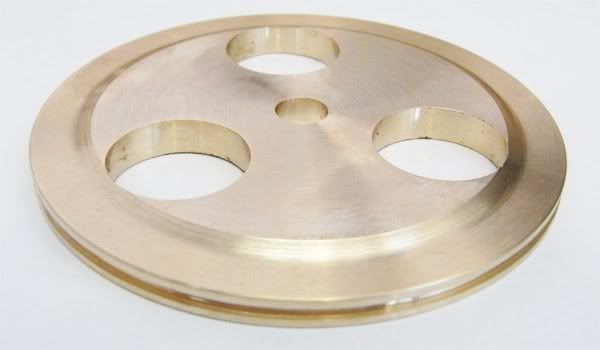
Flywheels from plate revisited.

Home Model Engine Machinist Forum

Help Support Home Model Engine Machinist Forum:

This site may earn a commission from merchant affiliate links, including eBay, Amazon, and others.
Alan,

After a while you will realise there is usually a little bit of weird humour sometimes in my posts, so don't take them too seriously. Just take them for what they are, a bit of light relief.

John
 
Bogstandard said:
Alan,

After a while you will realise there is usually a little bit of weird humour sometimes in my posts, so don't take them too seriously. Just take them for what they are, a bit of light relief.

John

The humour is appreciated!
 
John,

Great writeup. I really appreciate all the time you put into these posts.

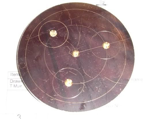
I can't quite tell from the photo, but the 'spots' around the edge look somewhat like a recessed rivet. Nice look. What did you use to make these marks?

Scott
 
John,

The FLYWHEEL program will do straight spokes very nicely, thank you very much. I've used it numerous times in that mode. Simply specify d1 = d2 or theta1 = theta2.

The only rewriting it needs is an option for locating the recesses in the spokes for the rhinestones. :)
 

Scott,

This is a 5/16", No 8, 60 deg end mill. Because the recess is very shallow in the centre, it will only penetrate about 50 thou, but I only go about 30 thou deep.

DSCF4171.jpg


Marv,

In words of two syllables or less, can you tell me what input I should be putting to get straight sides, this is the input to obtain what my wheels were done at. I must be doing something wrong somewhere.

3spokesettings.jpg


John
 
Marv,

Just had a play about with your prog, and got it to make straight sides, but they end up too wide (over 1") for my needs.
I will have to go back to my own method of drilling four holes for the cutouts. Its easy enough for me to do.

But your program does make real classy tapered spokes, and I have used it before and got great results.

John
 
John,

Referring to the diagram that's included with the FLYWHEEL.ZIP archive.

d2 = offset of inner hole from central axis of spoke

d2 = r2 * sin(theta2)

r2 = radius of inner holes [0.5 in your case]
theta2 = 180/N where N = number of spokes [180/3 = 60 in your case]

Therefore:

d2 = 0.5 * sin(60) = 0.433"

When the program asks for d1 (prompt says "offset from spoke CL to outer hole center"), simply enter 0.433.

Now, when you examine the output, you'll see that the inner and outer spoke widths are both equal at 0.616", i.e., non-tapered spokes.
 
Thanks Marv,

I have been waiting for your answer.
I went a slightly different route, but it does show because of the single inner hole, the spokes do get rather wide unless you make the inner hole larger.

At least I have the choice, my way and yours, and the one that I have just done has a very 'Mercedes' look. So I will be doing that with the others.

Many thanks

John

 
If you think about it, you'll see that the spoke width has to be related to the diameter of the inner holes. Those holes "span"* the space between two adjacent spokes so, for the spokes to become smaller, the holes must grow larger.

In my earlier post, I mistakenly typed cosine for sine in two places. I've gone back and corrected that now. Sorry for any temporary confusion I may have caused.

---
* "Span" is used here in a decidedly non-mathematical sense. For the proper mathematical relationships, refer to the diagram.
 
mklotz said:
If you think about it, you'll see that the spoke width has to be related to the diameter of the inner holes. Those holes "span"* the space between two adjacent spokes so, for the spokes to become smaller, the holes must grow larger.

Or, you can drill the same size inner holes on a smaller radius...
 
Too late now, they are done and dusted.

Worked out at about 4 hours total from recessed blanks to having these done.
So it does pay to have the paperwork ready.

flywheels.jpg


John
 
I just tried Bogstandards "masking tape method"--I have to say, it works most excellently. Thank you, Bogstandard.---Brian
 
I really like the 60* endmill treatment - it provides a nice touch of Victorian Steam-Punk. Very nice work, and thanks for the lessons.
 
I recently tried it too and I'm pleased with the results even though I haven't finished yet as I have to make a tapping tool before I make the boss.

pulley5.jpg


pulley8.jpg


pulley10.jpg

AFter this photo was taken the lathe jaws were opened up to make it more steady .

pulley11.jpg


pulley12.jpg


Not finished yet but pleased with it so far for my first try at something like this.

pulley18.jpg


Latest posts

Back
Top