Flywheel mounting options.

Home Model Engine Machinist Forum

Help Support Home Model Engine Machinist Forum:

This site may earn a commission from merchant affiliate links, including eBay, Amazon, and others.

Metal Butcher

Project of the Month Winner!!!
Project of the Month Winner
Joined
Dec 28, 2008
Messages
1,731
Reaction score
9
On my past small steam/air engine projects all of my flywheels were mounted using set screws. To avoid the damage a set screw can do to a shaft, I would cut a small 'pillow' from a 1/16" brass rod and drop it down the threaded hole before installing a set screw. This works well and allows the fly wheels to be repeatedly adjusted or removed.

This won't work well on my current project of building Hamilton Upshur's I.C. Farm Engines since the torque force at the crank shaft will be greater than anything I've built up to date.

Hamilton stated, "Its weak point is the set screw attachment of flywheels, as key fitting is not feasible for many builders." He recommends drilling into the shaft for the set screws. I'd rather not use this method since its a one time hit or miss proposition, that won't allow for any adjustments. And as in the past, their will always be a need for final adjustments, such as matching up the spoke position on engines that use two flywheels.

Any way, that's my position on adding key way's, or drilling into the crankshafts at an angle for set screws.

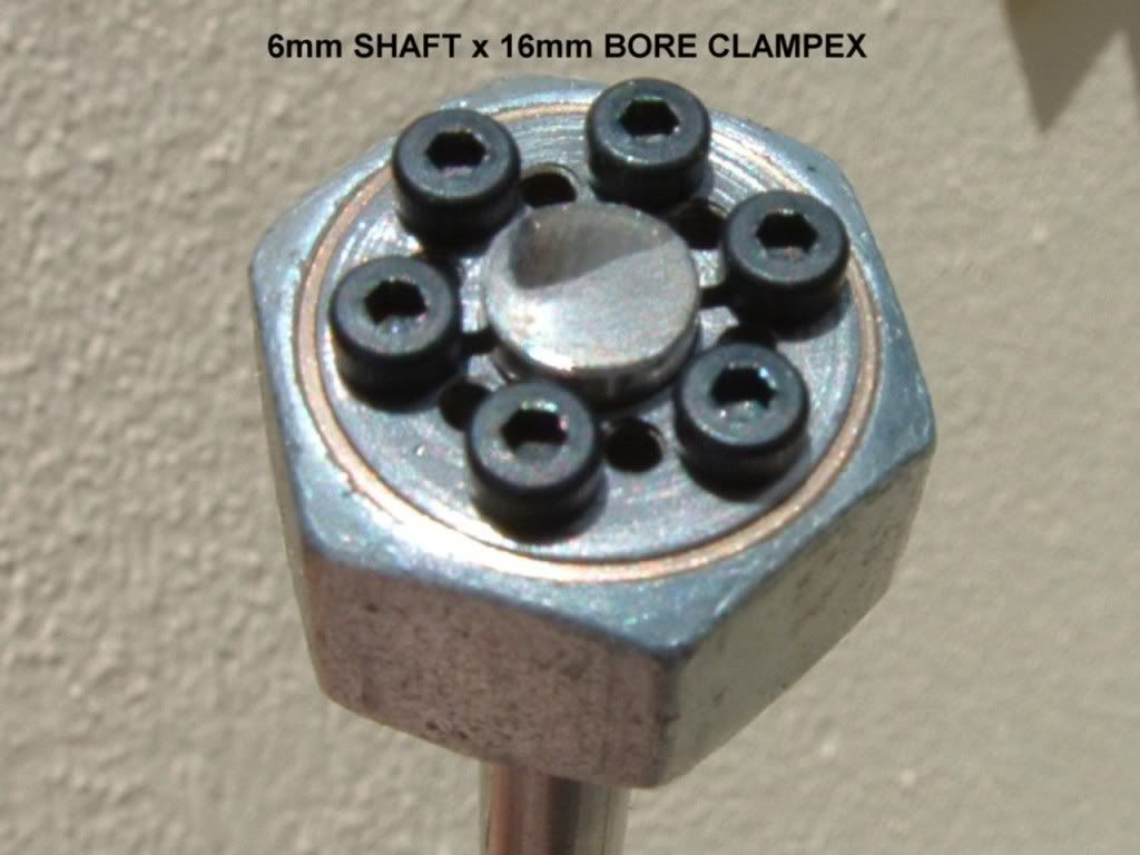
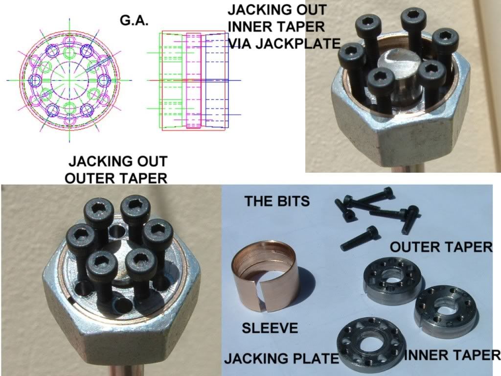
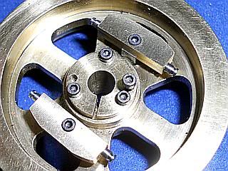
I recall seeing the use of locking tapered hubs by someone here on the forum. A simple and repeatable design using standard basic tooling would be the way to go. Maybe using a tapered end mill, or tapered pin reamers? Both of which I happen to have. Does any one have a 'beginner proof' design or method of accomplishing this goal?

-MB
 
MB,
I did a taper hub for my Tiny build.
HitMissParts-0004.jpg


It is too small for what your engine as it is for a 3/16 shaft, but you could scale it if if you wanted. I made the internal taper as a separate part that I Loctited into the flywheel so all I had to do in the future is make a straight bore in the flywheel and install it as opposed to setting up to do a taper bore in each flywheel. I did a mini production run so I have them on hand.

If you want, I can post a drawing of these parts, but it is just my working drawing. Accurate, but not to good drafting standards. Taper is not critical. I used a 12 degree include angle, 6 degree per side, and you should not go smaller than this or it will be difficult to separate the hub for removal or adjustment.

Gail in NM
 
Here is the drawing of the Tiny hub that I am using. Remember, Working drawing -accurate, but not in good drafting practice.
Gail in NM

View attachment FLYHUB.pdf
 
Hi Gail. Thanks, Your posted picture jogged my memory. It was 'your use' of a tapered mounting that was buried deep in my memory. The use of a separate sleeve in a strait bored flywheel is a great idea. If the sleeve with the internal taper goes south, a replacement sleeve is much simpler, compared to replacing a buggered up flywheel casting. Your picture shows only one split on the tapered collar and that confuses me, thinking that three cuts like that on a 5-C collet would be needed for a concentric running flywheel. The only problem I would be facing is getting both of the tapers equal on the sleeves, and their O.D.'s identical. It might be a bit too soon for me to attempt this on multiple pieces, and expect consistent results.

A cut and test method could work to get all the locking hub flanges in the same spaced position, and locking the entire flywheel assembly on a mandrel between centers for a light cut to equally size and true up the rim could work.

Thanks again Gail, certainly is all new to me and a lot to mull over in my mind.

-MB
 
MB, a single slit in the tapered bushing is all that's required. The straight bore that fits over the crank should be a close enough fit that there will be very little movement and concentricity won't be a problem. Also, as you tighten the screws, compression happens uniformly all the way round.

Although the tapered bushing is easy enough to do, here is an alternate method I have used very successfully on several engines. Less complicated, won't booger the crank, and cinches up really tight.

1482fea2.png


Chuck
 
cfellows said:
MB, a single slit in the tapered bushing is all that's required. The straight bore that fits over the crank should be a close enough fit that there will be very little movement and concentricity won't be a problem. Also, as you tighten the screws, compression happens uniformly all the way round.

Although the tapered bushing is easy enough to do, here is an alternate method I have used very successfully on several engines. Less complicated, won't booger the crank, and cinches up really tight.

1482fea2.png


Chuck

With my limited experience, the simpler, the better. I had a similar idea using a split end bushing (cut across one third the width of the flywheel) that would stick out say 1/4" past the width of the flywheel hub, the area protruding out side the flywheel hub would be machined to a small/thinner flexible diameter. Then a solid collar 1/4" wide slipped over the reduced bushing with one set screw through it to clamp down (at 90 degrees to the split) on it, and compress the two halves of the exposed bushing that goes through the entire bore in the flywheel. This would give a nice clean look and simple solution for a beginner. Any thoughts on this, has any one tried this approach?

Chuck thanks for posting a very good, yet simple way of mounting a fly wheel.

-MB
 
GailInNM said:
Here is the drawing of the Tiny hub that I am using. Remember, Working drawing -accurate, but not in good drafting practice.
Gail in NM

Thanks Gail, the drawing makes every thing crystal clear. The drawings are really good and easy to read.

-MB
 
I think the single piece solution I posted would give you a more secure result. Assuming your crankshaft is 3/8" diameter, I would start with a 7/8" round bar. The part that presses into the flywheel can have a pretty thin wall, maybe a 3/8" ID and 1/2" OD. For the clamping screw, I would probably use at least an 8-32 and maybe a 10-24 SHCS, so the wall thickness of the flange probably needs to be 3/16" (for an 8-32) or 1/4" (for a 10-24) clamping screw. This would need to be drawn to scale to make sure the flange is large enough to accommodate the head of the SHCS.

Here's a picture of a smaller application. The crankshaft is 1/4". The OD of the flange is probably 5/8". I believe the clamping screw is either 4-40 or 5-40.

47a2fb9e.jpg


Here's a larger application. This is a steam engine flywheel. The crankshaft is 1/2" diameter and the flange is 1" diameter. The clamping screw looks to be a 6-32 or 8-32.

450d9772.jpg


Chuck
 
Chuck, so the grip on the shaft is accomplished with the collar contact on one side of the shaft, and on the opposite side the collar contact is on the remaining part of the sleeve that goes through the flywheel.

Based on the drawing you posted earlier, it looks like 50% of the the exposed part of the sleeve is milled away?

My thought was to slit through both sides of the exposed part of the sleeve, giving two splits compared to the usual three on a 5C collet. Would a split collar could still work? Are you saying my idea of a solid collar with a set screw to compress the split halves of the sleeve won't work?

Bear with my questions Chuck, I'm new to this and need to understand all the options and their viability.

-MB
 
I've been out all day, so just now got home and found your message.

Chuck, so the grip on the shaft is accomplished with the collar contact on one side of the shaft, and on the opposite side the collar contact is on the remaining part of the sleeve that goes through the flywheel.

Sort of, if I understand what you are saying. The SHCS pulls the flange or collar tight so even pressure is exerted on the shaft all the way around not just on one side.

Based on the drawing you posted earlier, it looks like 50% of the the exposed part of the sleeve is milled away?

Note really milled, just a slot cut half half way through the sleeve with a hacksaw.

My thought was to slit through both sides of the exposed part of the sleeve, giving two splits compared to the usual three on a 5C collet. Would a split collar could still work? Are you saying my idea of a solid collar with a set screw to compress the split halves of the sleeve won't work?

No I think your method would work. However, rather than a solid collar with a setscrew, I think a split collar with a tangential screw to pull the split closed would provide better grip against against the dual split sleeve. I would probably have the split in the collar half way between the two splits in the sleeve.

Chuck


Chuck, The drawing posted in reply #8 is confusing me, I just can't interpret this drafting style due to my lack of experience. The lighter shaded area of the upper half of the sleeve in the 2nd drawing on the right gives the impression that the sleeve area under the collar is milled out to the end. The drawing on the left shows an 'L' shaped line that looks like the beginning of that milled out area.

After reading you last post and looking at reply #8 again I think I understand what you did. You have two cuts, one strait down 'vertical' into the sleeve down to its half way point, showing in the first drawing on the left, that I referred to in the above paragraph as the 'L'. The second cut is through the top of the sleeve, it starts at the end of the sleeve and goes horizontally all the way to intersect with the vertical cut. Its split is just below the split in the collar shown in the drawing on the right, but misinterpreted by me.

I hope I got it right this time.

-MB
 
Yep, I think you've got it. Here are a couple of drawings I did in Alibre. Maybe they'll help.

48c1115d.jpg


d95c3398.jpg


There are a couple of lines in the drawing that I don't know how to get rid of. Hope it's not confusing.

Chuck
 
Yea Chuck, the drawing confirms what I thought you did. I understang why the need for the vertical cut. Without that cut, and with only a single horizontal cut it would take a great amount of pressure to get enough compression on the sleeve to grip the shaft. I think I'll try out my idea of splitting the sleeve through both side length wise. This way each half won't need to compress very much to get a good grip on the shaft. The split collar seems like it would provide more clamping pressure than my idea of a solid collar. The reason I'm leaning towards it for cosmetic reasons. It only needs to be slightly larger than the sleeve in o.d. to accommodate the set screw, minimizing its presence.

As an experiment I'll make one set screwed solid collar, and one split collar, clamp a shaft in the vise and see what it takes to break the flywheel loose. I'm hoping the smaller solid collar idea will work well enough.

Thanks Chuck.

-MB
 
Attatched is a "Clampex" design - this particular one is for an 80mm shaft and handles 27000Nm - it is a very effective design.

I haven't tried to make a small one but they are simple, compact, very effective and look very industrial which would be nice on a model.

It consists of an inner and outer taper in a thin walled outer shell (all split), within the shell is a further ring which serves as a jack-apart plate for disassembly.

The whole thing is held together with cap screws - which are also used to jack it apart - neat.

The *.dwg file is incomplete but the part per layer should be self explanatory.


View attachment Dump.dwg

clampex.JPG
 
Allright - Had a complete rush of blood to the brain and decided to make one for use on my beam engine flywheel.
clampexx.jpg

The bored out nut on the outside is just my "proof of concept" part to see if it works.

Handles 7.5 ftlbs (10Nm) before slipping - would probably be higher with a steel sleeve (I used P/Bronze).

Helluva lot more work than a grubscrew - but it looks really neat.

Behaves just like its much bigger industrial cousins in that you have to go round the bolts several times to get it fully seated.

Similarly the extraction process is much the same.

clampexassy.jpg


Attatched ACAD drawing if anyone's interested.

Ken

View attachment Dump.dwg
 

Latest posts

Back
Top