Flame Eater begins...

Home Model Engine Machinist Forum

Help Support Home Model Engine Machinist Forum:

This site may earn a commission from merchant affiliate links, including eBay, Amazon, and others.
Nearly there Mike, looks spot on so far. I couldn't be bothered messing with the crank so just left mine as a disc - doesn't seem to have made any difference.

Nick
 
The small parts take longer than the big parts. Two parts plus drill and tap the crank-web took me about 6 hours today. It didn't help that I had to make the crank pin twice. :wall:

Crank Pin. 10-32 outside thread, 4-40 inside. The whole thing is about 6mm long. I can barely see to work on it even with my magnifier glasses. I made the whole part then installed in on the crank. If I had to do it again, I'd make the 10-32 threaded end, install it, put the crankshaft in the 4-jaw, offset it, and turn down the rest of the crank pin there. Would be much easier to hang onto and would be better aligned with the crankshaft.
IMG_2631.jpg


Crank Pin installed. I hope it's square enough because I don't look forward to making another:
IMG_2635.jpg


Crank Pin screw. The macro setting on the camera works too well--you can see all the defects:
IMG_2633.jpg


All of it put together. It's amazing how well that little bearing works:
IMG_2639.jpg


Bearing support. Two pieces fly-cut to thickness then super-glued together. Rough layout then center-drilled for the bearing pocket:
IMG_2695.jpg


One done--poorly. I hate boring on the mill compared to the lathe. Too many start/stop/measure/adjust. And it went from no fit to drops right in. There is no slop but it's not a good press fit I wanted. Either I'll put a couple dimples in the sidewall with a punch or a drop of loctite.
IMG_2697.jpg


IMG_2700.jpg


Flipped over, re-located the other hole with my co-ax and bored another bearing pocket--poorly. Drilled some decorative holes. The Mickey Mouse ears at the top will end up being small scallops at the top of the support. In my defense--these are the first two bearing pockets I've ever done on the mill.

IMG_2707.jpg


More tomorrow.
 
Bearing supports done. Got a nasty scratch in one when I was roughing out the final shape on the bandsaw. And a minor catastrophe. I snapped the end off a center drill in the last mounting hole. Luckily it's a thru-hole so I was able to drill from the other side.

IMG_2709.jpg


IMG_2711.jpg


Although these are made pretty much to plan width- and depth-wise, I still get some rubbing from the flywheel. I guess 1mm clearance is not enough for my not-so accurate machining. I'll need a few spacers between the flywheel hub and the bearings to compensate.
 
They look very similar to mine! I didn't bother with the mounting lugs though, wanted to make it as simple as possible, then I decided it looked too plain and added decorative holes and scallops! I've learnt something from yours though, as I tried to just plunge with a slot drill to do the scallops and it always ended up moving, better idea to drill the hole and mill away like you did.

I had the same trouble with getting the good fit on the bearings, I used much smaller ones anyway but I don't have a boring head so I just used an end mill and plunged but it ended up too big, as you say a couple of centre pop marks to make it grab and a bit of loctite worked fine. Actually, I remember getting too much of a press fit on one of the bearings and it must have been enough to squeeze the bearing which prevented it from rotating so there's something to be said for a sliding fit.

On my crank pin I left quite a bit of play side to side and on the diameter to allow for out of squareness and glad I did - at the model engineering exhibition a chap brought over his engine which he'd made to a much better standard than mine but when I was helping him trouble shoot one of the things I pointed out was that his was actually too accurate, the good fit he'd produced actually caused a very slight amount of binding and it only takes the tiniest amount of excess friction to stop these things running. The other thing was on his valve, there is meant to be quite a big clearance between it and the pushrod, his was a nice fit but you need some slop in it!


Nice work, can't be far off now! :bow:

Nick
 
help!!!
i wanna to know it.
how much heavy of the flywheel?
 
Your bearing supports look good Mike, I wish I'd done them like that now! I wouldn't worry about the bearing fit too much, I don't believe it's too critical in the scheme of things. Where is the flywheel rubbing?

Vic.
 
Forgot to mention that - I had the same problem with my cast flywheel, had to put some spacers in there too! :big:
 
Nick, Imitation is the sincerest form of flattery. Sorry for copying your design--but there's only so many ways to make these things. :big: Doing it this way is easier than makeing shorter supports and then turning 4 legs for it. I think I'll make some sort of bracket instead of legs for the cyl too--just to be different.

Vic, If I set them up with the "side the bearing presses in from" towards the flywheel, I think they'll work but the clearance is minimal. The other way around the wheel rubs on the supports. But I kinda like the mechanical look with the bearings showing on the outside so I think I'll make up some tiny spacers.

Carkwi, don't know the weight. It's not to plan 'cause I didn't have the right size materials. And I'm not sure you'd want to copy a non-finished, non-running version anyway. Ask again after I get it running.


No no, sorry, I didn't mean it to sound like that! You're right, that's the only thing I could really think of too, couldn't be bothered with making all the fancy turned columns and cut outs in the side etc. Also, there was more room for error that way! If you look at mine compared to Bogstandard's you can see mine are very similar to his too!

I liked the bearings showing also!

Doing great ... :bow:


Nick,

Mine was made to see if it would run, so was only very basically built.

Sometime soon, it will be getting a complete facelift, and only the cylinders and other major bits will remain, everything else will be 'blinged up'.

I mentioned this the other day, as long as the major parts and positions are kept to plan, everything else can be whatever your imagination can come up with.

That is what makes us all individuals, we all make the same engines, but none seem to look exactly like what has gone before.


John

 
Spacers. Made two 1mm thick and two 2mm thick spacers. What a pain. I don't know how guys work with stuff this small all the time.:
IMG_2717.jpg


Cyl support almost done:
IMG_2714.jpg


Cyl Support done. I copied the decorative holes from the flywheel supports:
IMG_2720.jpg


The next project will be the base. Measuring everthing and laying out all the holes will take a while as I've drifted from the plans somewhat. The important stuff I tried to stick too as close as possible--the other's, not so much. I'll lay it out in DeltaCad, my used-bookstore find of a 2-D cad program that cost all of $8.00 about 10 years ago. It still works! :)
 
Thats looking really nice Mike, I love the cylinder support!

Vic.
 
Just one thing Mike,

You baseplate is going to get hot real quick. Even using the normal thin standards for the cylinder, after ten minutes running, the baseplate is too hot to hold.

If you have trouble getting the engine to start, the first thing would be to reduce the contact areas. I found the engine has to be fairly hot to even start to pop.


Bogs
 
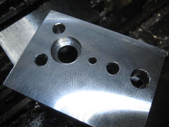
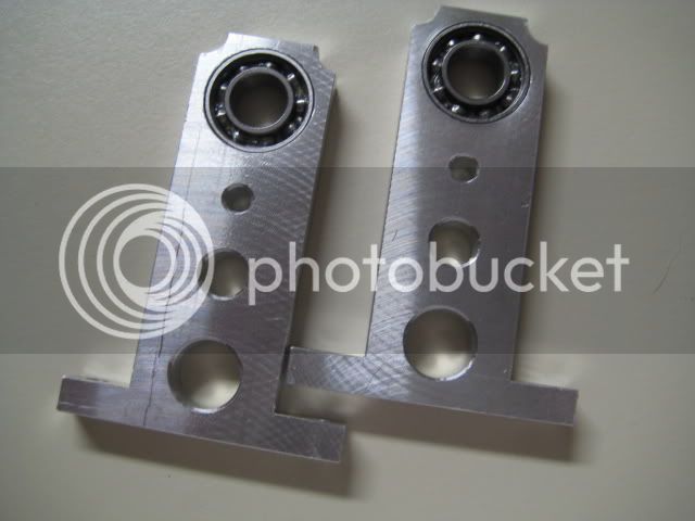
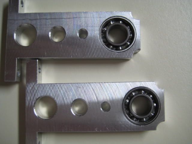
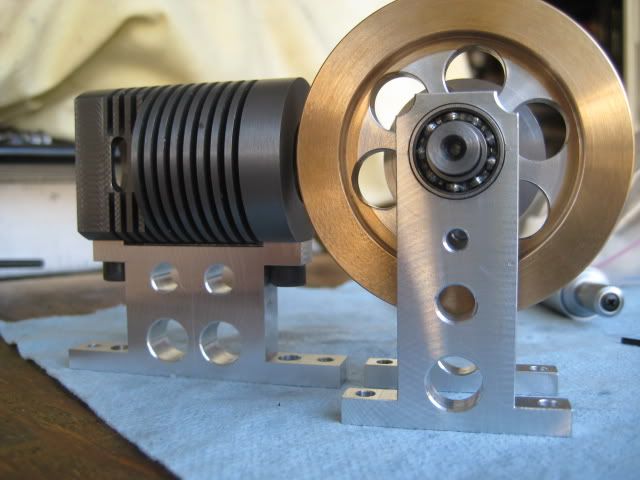
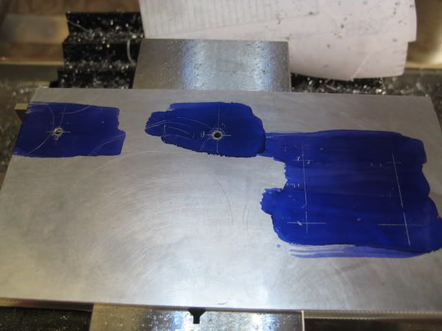
Worked on the base today. DeltaCad to the rescue. I took it all apart and spent 1.5 hours with my mic and caliper measuring and laying out for SIX freekin' holes. But they have to be close to perfect to line up everything and cut down on friction. This is the result:

dca.jpg


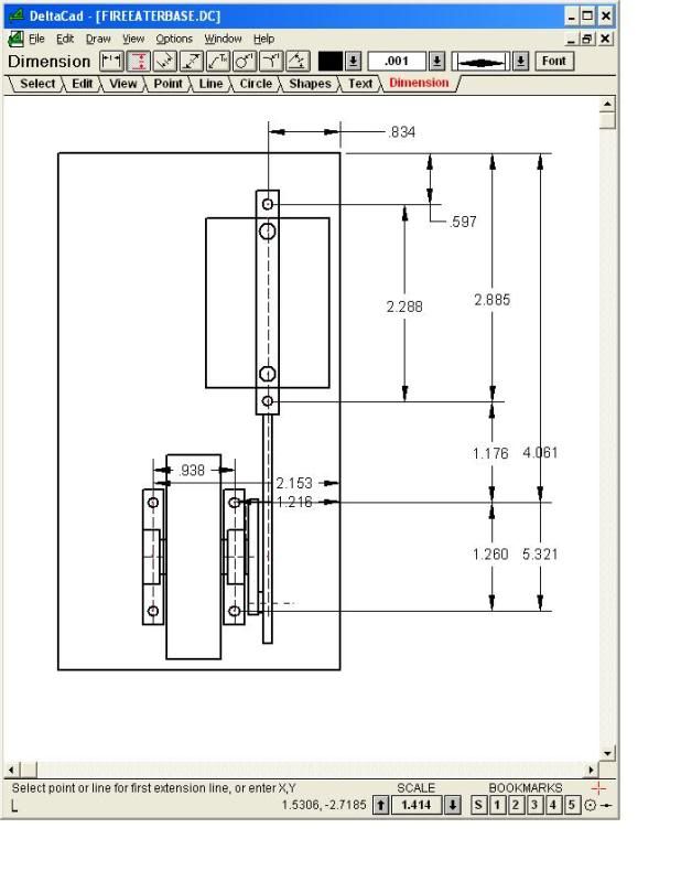
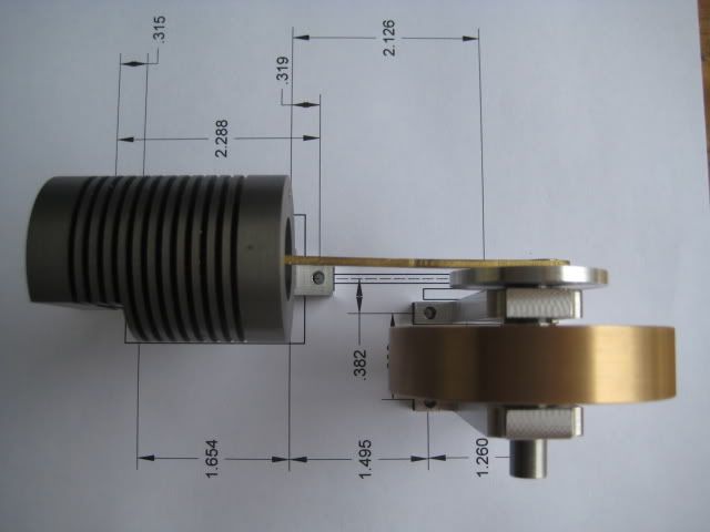
I printed it out to scale and lined up the parts just to make sure:

IMG_2723.jpg


IMG_2724.jpg


IMG_2726.jpg


Time for the base itself. 6" x 3-1/4"--roughly. Stock was too long for my 4x6 bandsaw so a little enjunearing was needed:

IMG_2727.jpg


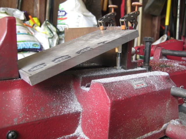
Squaring everything up. Saw this trick of using 1-2-3 blocks to support parts too big for the vise:

IMG_2731.jpg


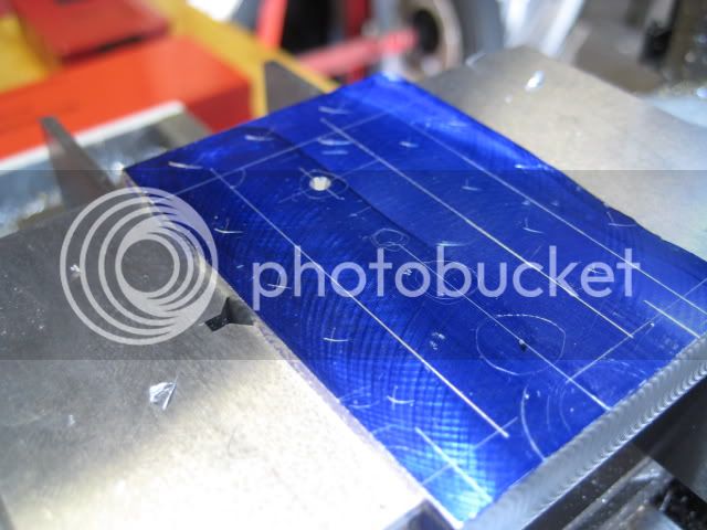
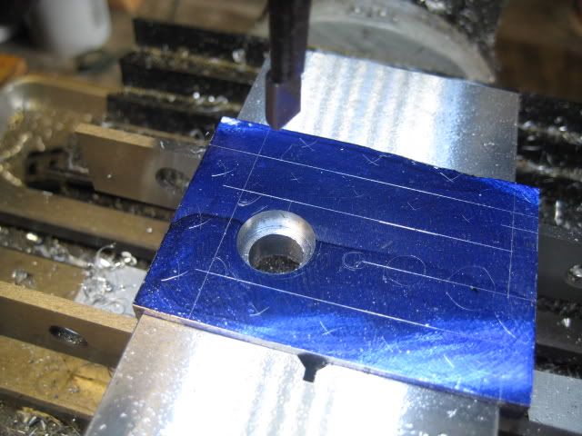
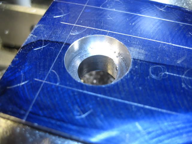
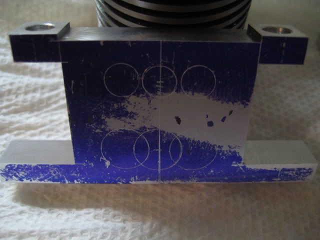
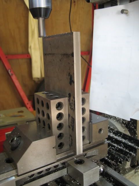
Flycut, dykem, scribed, then drilling:

IMG_2733.jpg


Polished the base with some wet-dry on the surface-plate. The mirror finish looks better on film than up close. There are still lots of scratches--some from my heavy-handed scribing.

IMG_2741.jpg


IMG_2740.jpg


IMG_2738.jpg


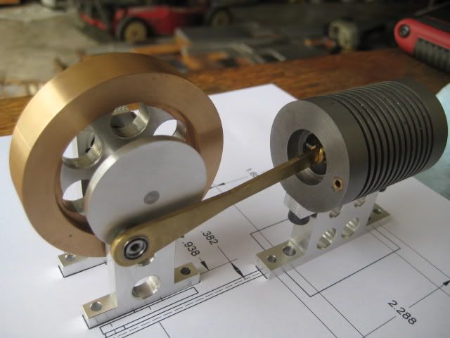
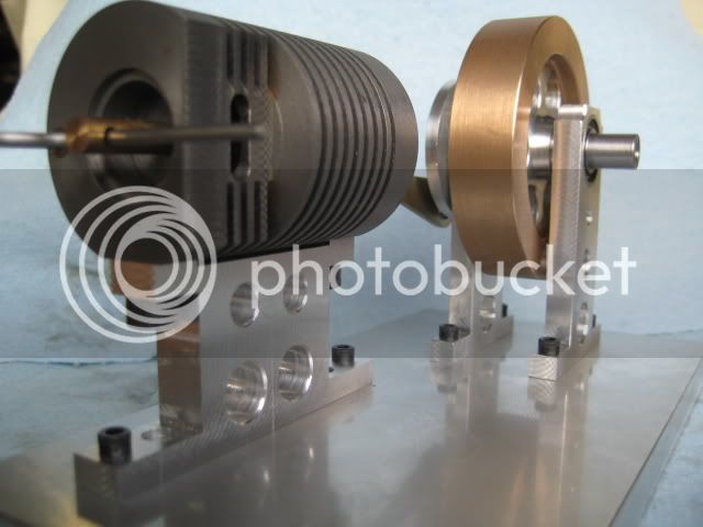
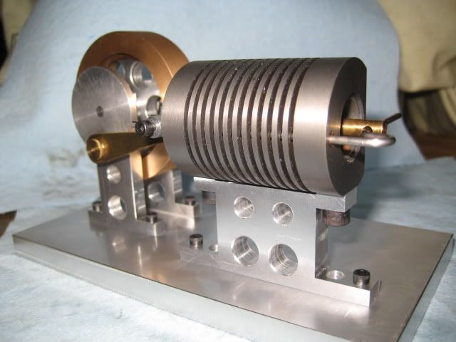
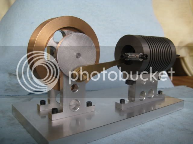
Looks good don't it?

I need to make a burner. Nothing handy--I scrounged everywhere around the house. It's almost done. I couldn't resist--I had to try something. So I got one of my wife's alcohol room-freshener lamps. It's the size of a grapefruit and way too unwieldy to get the flame close enough. BUT...it did show signs of life once. I was stoked...And now it smells nice too. :)


Then while talking to my brother on the phone--he suggested a butane lighter--like for starting
up the fireplace. Well, I just happened to have one handy...AND GUESS WHAT? It's a RUNNER!!!

Absolutely amazing. I cannot be happier. Click below for video:


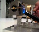
SAAAAA-WEEEEEETTTTT! It's gonna be so much better with a real burner and some polishing here and there!
 
It is a good feeling isn't it.
I do like the flywheel you have done it is a looker!
Good job!
 
Back
Top