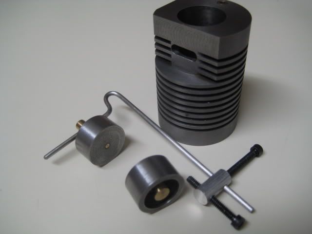
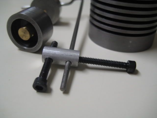
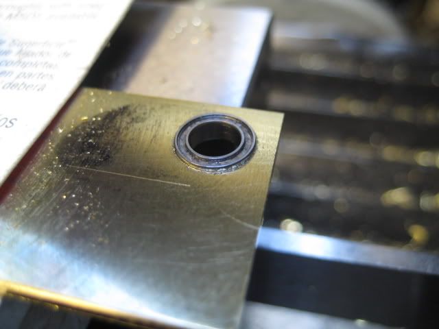
Flame Eater begins...

Home Model Engine Machinist Forum

Help Support Home Model Engine Machinist Forum:

This site may earn a commission from merchant affiliate links, including eBay, Amazon, and others.
Bushing installed:
IMG_2465.jpg


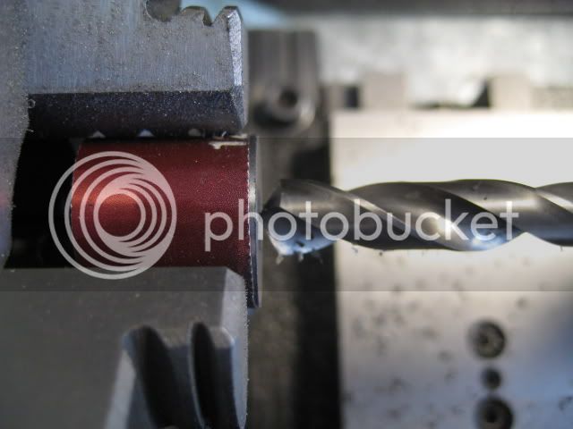
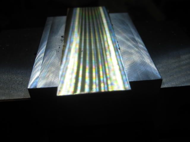
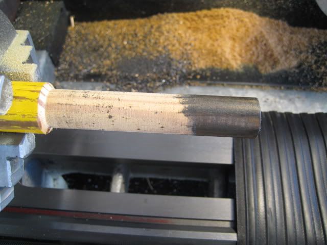
My 1st attempt (ever) at lapping. Turned a broom stick into an end-lap (nice fit at the end and smaller in the middle so I could run the cyl all the way past). Added a bit of valve grinding compound and had at it. Was looking more for a polish and smoothing than trying to change the size.
IMG_2471.jpg


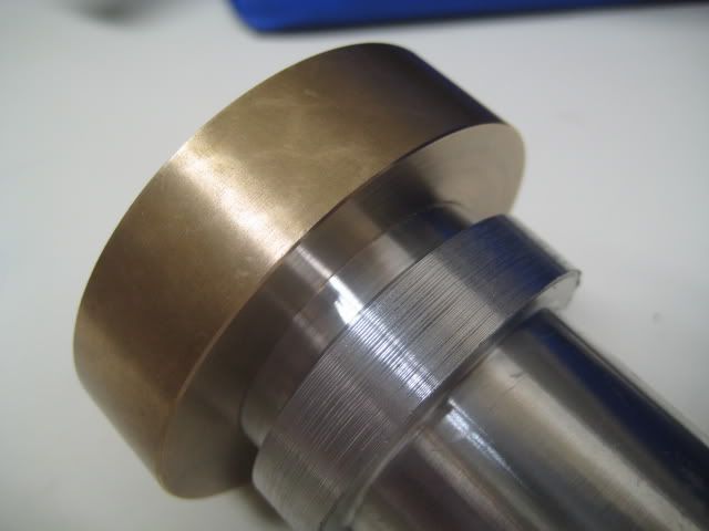
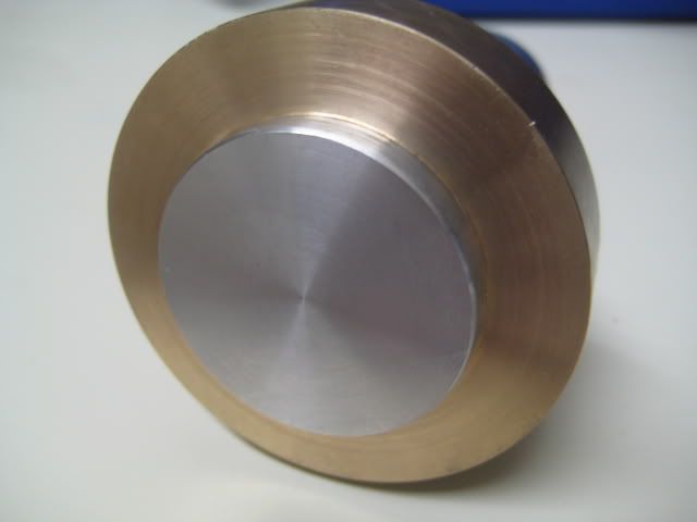
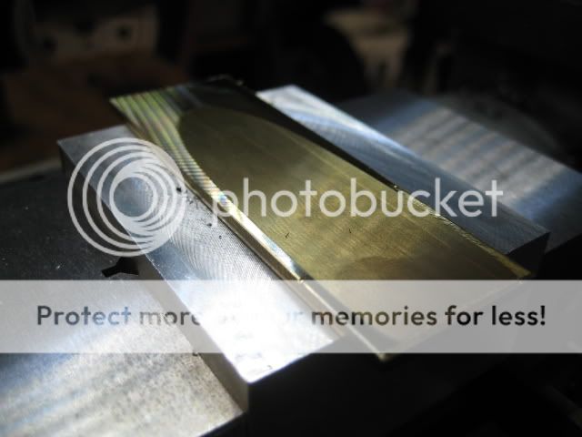
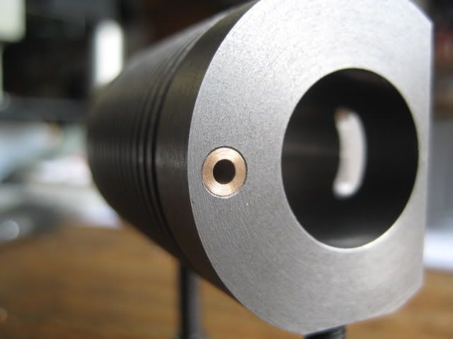
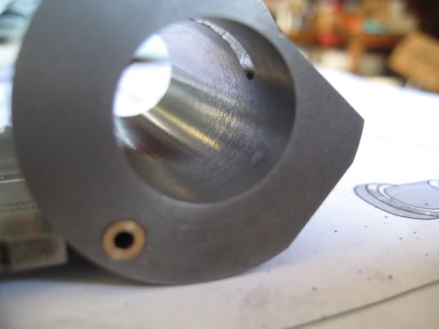
Rot-Roh Scooby! It revealed a small flaw. Looks like drilling for one of the cylinder mounts it almost broke through. You can see the pimple in the lower right--cannot feel it at all though:
IMG_2475.jpg


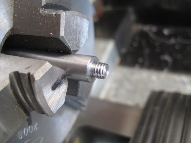
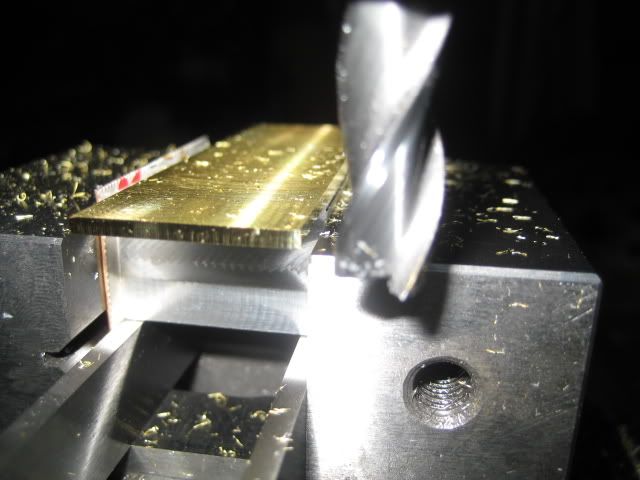
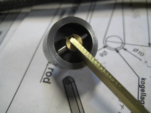
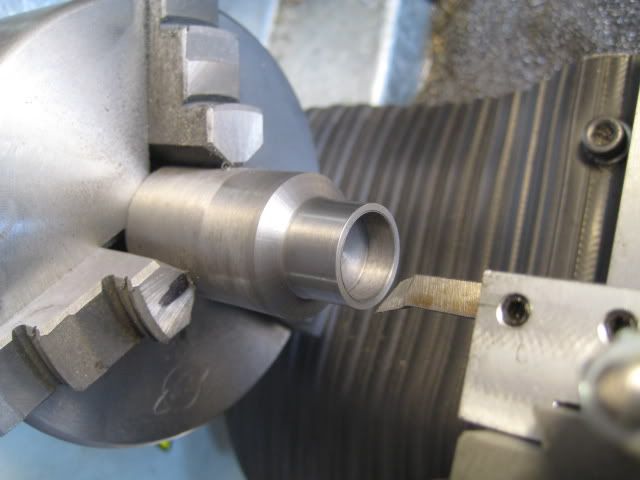
Piston and Valve were next. 1st attempt was a biG fat PHAIL! But it gave me some good measurements to work from. .7105 fit but was way too tight and .7070 was way too small. This 2nd attempt ended up at .7095 and seems like it will work. I'm not doing them again unless they don't.
IMG_2478.jpg


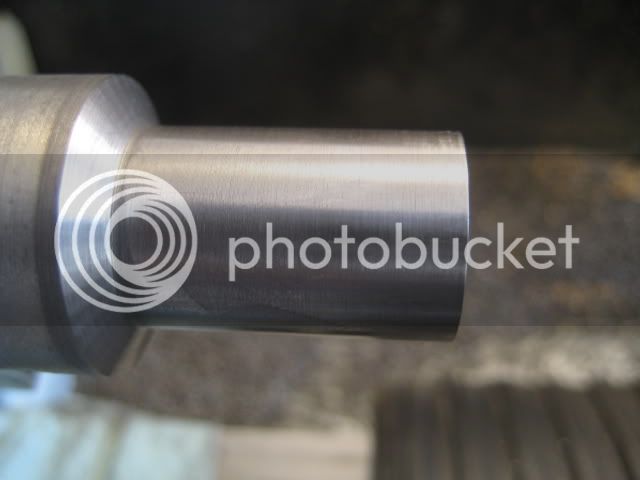
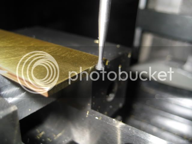
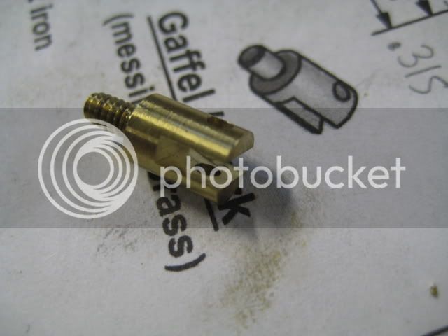
Parted off a chunk for the piston and this is the valve hollowed out:
IMG_2481.jpg


It was a long day with a little bit of progress. That's where I stopped today.

This is a movie--click to view in Photobucket. It's the valve and a 4-40 screw substituting for the pivot stud and only the rough cut piston (not even hollowed out) installed in the cylinder. It's all completely dry and clean--no oil. Moving the valve makes the piston move! Hopefully this is close enough tolerances (and not too loose) for it to run.
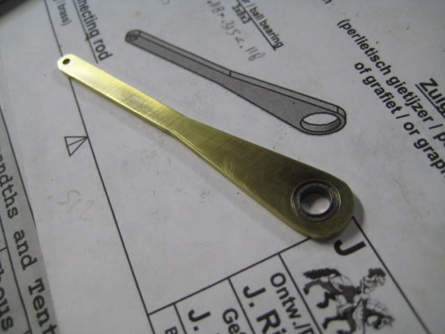


It will be a good enough fit and should work as long as the friction is low enough - it looks it from your video - nice 1 :bow:
 
No need to worry over that almost break thru, that isn't in a critical area at all.

I would suggest you look at Nick's build before bending up the wire operating rod, and think about putting a stop on it near the bend as Nick did.
Because I followed an earlier plan, mine was silver soldered at a sharp right angle and actually works as it's own stop. Because of that, the sliding valve always goes to the perfect inwards position.


Bogs
 
Bogstandard said:
I would suggest you look at Nick's build before bending up the wire operating rod, and think about putting a stop on it near the bend as Nick did.

I saw that. Was going to add a collar and then had an idea. Make the rod that goes through the valve longer on the "flame-side". Long enough to reach to the opposite side of the cyl. That way it way it could act as a stop. Today I stumbled upon a youtube vid of a design that looks like that!

[ame]http://www.youtube.com/watch?v=GWNjaxVmUzQ[/ame]

It's hard to see but they don't have a collar but do use the bent rod design. Worth a try--if it doesn't work it's just a little trimming and adding a collar.

Mike
 
Good idea, that should do the same trick without the messy collar. I also did it because I was experimenting with different amounts of overlap when I was struggling to get it to run but I can't remember whether I tried it without the collar. Think it'd need something to stop it being sucked in too far though.

Nick
 
You are making a lot of progress Mike. That cylinder looks great to me...keep up the fine work.

Bill
 
Thanks for all the comments. Got a little done the past few days.

Piston, valve, push-rod, striker. Push-rod is part of a broken spoke from my mountain-bike (I have a few of those :():
IMG_2503.jpg


Striker (will fine tune the bolts later):
IMG_2506.jpg


Extra length push-rod (will trim to final fit later):
IMG_2507.jpg


Now a question. It seems the valve only overlaps the port by about 1.2mm when it's closed. I've double checked all my measurements and they're pretty much spot on. Is this overlap enough? If not, it means I may need to make a longer pivot stud for the valve, drill the hole a bit higher up on it, or switch to a collar like Nick has so the overlap would be adjustable.

Got my bearings today. Tried a bearing supplier that I've used before--$12.00 US each for the big ones and $8 for the small one. ??? No thanks. Found them at a RC/Hobby store $14 total for two big and two small. Comparable to what I found on the internet so those will do for now.


And, finally, a tip (maybe?) to share. Here's how I set up for drilling to a set depth on the lathe.

Set a feeler gauge between part and bit (this keeps the tip of the bit from going into the center-drilled hole):
IMG_2498.jpg


Set DI at thickness of feeler gauge. I do this with the tailstock loosely clamped and wind in or out to get it set, then clamp it--love the cam-lock and the tailstock flag comes in handy:
IMG_2500.jpg


Remove feeler, wind tailstock until DI reads zero. Tip of drill would be just touching the part:
IMG_2501.jpg


Drill away. Need to work on a better mag mount for the DI though--that one's a bit big.

 
Great work and great pics too :bow:

I had mine running last night because my 4 year old wanted to see it - great to watch! Made me realise how critical the position of the flame is again!

Mine needs to heat up for about 10 mins with burner first as I use engine oil on it - I and a few other people have found this stops the combustion products from adhering to it necessitating strip downs. It causes too much drag on some peoples engines but on mine it seems to help seal too. The downside is it gets oil dripping on the base plate - I should really put an oil cup on the top of each end of the cylinder like 'poppin' flame licker has on the front end. These engines usually require heating first though, without oil they may run initially for a few seconds but then condensation forms and stops them, takes a while to get to temperature.

The 1.2mm overlap sounds about spot on so I wouldn't worry about that.

You're getting there, can't wait to see it running!

Nick
 
Today's progress. Flywheel. Turns out the solid piece of brass I thought I had for the flywheel wasn't big enough. And this other piece of "brass" tube I had is really a piece of bronze--or at least I think it is. PITA to cut and machine. I turned a piece of aluminum to press into it. Bronze in the toaster, Aluminum in the freezer and few whacks with a hammer and I got this. I think the two-tone is gonna look nice:

IMG_2512.jpg


IMG_2511.jpg


Started the Crankshaft:
IMG_2517.jpg


And whatever you call this piece--Crankweb, crankdisk, lobe? Anyway--here it is:
IMG_2521.jpg


I don't think I'll make it Y-shaped like the plan. Maybe drill some extra holes to lighten it up.
IMG_2522.jpg


Then started roughing out the flywheel.
IMG_2526.jpg


Planned on making it look like the plans. I kinda like the stepped look and shadows the rough cut lines make. Too bad none of it was measured and it would be too hard to replicate on the other side. Will have to incorporate a design like that into the next flywheel:
IMG_2527.jpg


That's as far as I got--thunder and lighting storms shut me down. I don't like leaving the expensive equipment plugged in during storms. Back at it tomorrow hopefully.

 
Nice. The two tone flywheel will set it off. Keep it up!

Dean
 
Turning the flywheel. What a pain. I think I used every tool I have--left hand, right hand, boring bar, facing tool. Changed countless times and re-angled to get it to cut the way I needed it to:
IMG_2531.jpg


Ohhhh, something shiny:
IMG_2535.jpg


Nice fit on the crankshaft. One minor screw up. You can see it comparing this photo and the one above. Below is the 1st side I did. I read the plans as the whole hub needed to be 10mm. Well, there's a step on the end that needs to be 10mm--the rest is supposed to be 14. I caught it when it was down to about 12mm--arghhh. No biggie, I turned the other side correctly and that will have to be where I put the grub screw so I have enough threads:
IMG_2548.jpg


IMG_2544.jpg


Onto the mill with it next time.
 
Got the flywheel holes finished last nite. 2 holes done:
IMG_2553.jpg


All 6 done:
IMG_2555.jpg


What I used to index the holes. Bolted flywheel to a plumbing fitting I had.
IMG_2556.jpg


Today I tapped for the for the grub screw. 6-32 (smallest I had) instead of 3mm. I just eye-balled the angle:
IMG_2560.jpg


Onto the connecting rod. Flycut a piece of brass. Super glued it to a piece of aluminum. The brass was shear-cut so the edges were rolled and it was cupped. This is after the 2nd pass:
IMG_2564.jpg


Finished flycutting one side. Took about 10 thou to get it flat. The other side was just as bad.
IMG_2566.jpg


Truing up the edges:
IMG_2574.jpg


Wiggler finding an edge so I can locate the bearing hole:
IMG_2576.jpg


Bearing test fit. My 8mm drill comes out close enough. Might need a drop of loctite just to make sure:
IMG_2580.jpg


Then a screw up. Used the dials to move over for the "wrist pin" on the piston end. Easy enough...ready to drill...and grabbed the 2.5mm bit instead of the 2mm. :wall: It'll probably still work but now I've got to turn down a pin instead of just using one of those broken bicycle spokes I've got. Or I might just make another connecting rod all together--that piece of brass is wide enuf still.
 

Looking good!

I'm a big fan of the aluminum centre and brass outer rim flywheels. Done it a few times myself.

Nice progress pics too.
 
Beautiful flywheel.
I like the two-tone too.
What did you use to chamfer the holes?
 
>winklmj: Too bad none of it was measured and it would be too hard to replicate on the other side. Will have to incorporate a design like that into the next flywheel

I've run into this situation a couple of times. The thing is, you can never see both sides of the flywheel at the same time so there's nothing to compare against. You can make one side completely different than the other and it looks fine from either direction.

The flywheel looks nice. Reminds me of my last one but I had to use aluminum on the outside of the wheel. Not as much weight but the inside brass added some weight that wouldn't have been there otherwise.
 
Beautiful job on the flywheel Mike, and I like the use of the plumbing fitting too as a guide for the hex hole pattern.

Bill
 
Thanks again for the comments.

I have a set of chamfering/countersink bits I used on the flywheel holes. But none are the right size--too small or too large. The too-large one (which I used gently while chucked up in a hand drill) rubs on the outer rim of the flywheel so it can't go straight into the hole as it should. I will come up with a way to do a better job of it but for now I'm in get it built and make it run mode. Once it's working (chickens...hatched???) I'll clean and polish it all up.
 
Connecting rod done. Since I had enough brass, I went ahead and made a new one with the proper sized 2mm hole in the piston end. Need some touch up work still, I free-handed the radius on the ends:
IMG_2594.jpg


My shop-made slitting-saw arbor (just the arbor--not the MT3 end-mill holder it's installed in):
IMG_2604.jpg


Slitting-saw cutting the slot in the piston fork. First time I've used it--I think it's scarier than a fly-cutter--so I took it slow (and I didn't want to saw into my vise):
IMG_2584.jpg


Piston fork done:
IMG_2592.jpg


Piston-end put together:
IMG_2598.jpg


I think the critical-pieces are done now. Bearing supports; stand-offs for everything; and a burner still to come. It's getting close...


Back
Top