
You are using an out of date browser. It may not display this or other websites correctly.
You should upgrade or use an alternative browser.
You should upgrade or use an alternative browser.
Finished modeling up engine, now time to build.
- Thread starter doc1955
- Start date


Help Support Home Model Engine Machinist Forum:
This site may earn a commission from merchant affiliate
links, including eBay, Amazon, and others.
- Joined
- Jun 4, 2008
- Messages
- 3,294
- Reaction score
- 636
Doing those spoked wheels without a rotab takes some real inventiveness! :bow:
As to Nick's comments on the frames, I think that with drilling the corner holes as Doc did, using a swivel base on the milling vise would make the cutouts fairly straightforward. And my clamping the material together both sides could be done at the same time.
As to Nick's comments on the frames, I think that with drilling the corner holes as Doc did, using a swivel base on the milling vise would make the cutouts fairly straightforward. And my clamping the material together both sides could be done at the same time.
doc1955
Gone
- Joined
- Aug 26, 2009
- Messages
- 1,261
- Reaction score
- 168
I just use a fixture witch consisted of a block of aluminum mater fact same one I used for the fly wheels.
I clamped in vise so it is setting above vise by a couple tenths on an inch and with a 1/4 end mill I mill an edge on x axis to be used for locating. Once you mill edge don't move table in y axis because your cutter is set in right position. now just put 2 pins in the holes drilled in side plate pull up to edge and move table on x until cutter will go into hole (oh yeah remove pins after clamping) and mill to other hole unclamp pick 2 more holes and repeat. You never have to move y axis just back and forth on x.
Hope this makes sense to you because it is quite easy to do.
doc1955
Gone
- Joined
- Aug 26, 2009
- Messages
- 1,261
- Reaction score
- 168
Well didn't get a lot done with work and snow removal after cut into my machine time.
Plus I use a different camera to start with and the photos didn't turn out.
So here is what I got accomplished for the week.
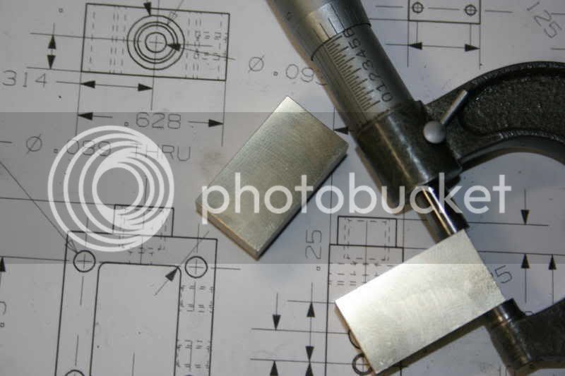
I grabbed a piece of steel large enough for the crank counter weights and faced the ends and drilled center hole to be a press fit to .250. Then I went to the mill and clamped in vise with a v-block and drilled the rod journal hole same press to a .250. After that I pressed pins into the holes so I had pin sticking out both sides of the blank. I used these pins to be able to load in vise and keep them parallel to tale by letting pins lay on top of vice while clamping. Hope I'm making sense here anyway I proceeded to mill profile after the profile was completed I cut it into 4 pieces 2 for each crank. Here I switched back to other camera and got some pics.

pressed a pin in each to use on lathe to face to right thickness.

Facing on lathe one one side is cleaned up push pin through and chuck in lathe and face opp side to thickness.

Here is the finished product I did dust the faces on a surface grinder.


Here I just stuck a set together temporally I need to turn up shafts and will pin the rod journal into place.
I will come back to that later.
Plus I use a different camera to start with and the photos didn't turn out.
So here is what I got accomplished for the week.
I grabbed a piece of steel large enough for the crank counter weights and faced the ends and drilled center hole to be a press fit to .250. Then I went to the mill and clamped in vise with a v-block and drilled the rod journal hole same press to a .250. After that I pressed pins into the holes so I had pin sticking out both sides of the blank. I used these pins to be able to load in vise and keep them parallel to tale by letting pins lay on top of vice while clamping. Hope I'm making sense here anyway I proceeded to mill profile after the profile was completed I cut it into 4 pieces 2 for each crank. Here I switched back to other camera and got some pics.
pressed a pin in each to use on lathe to face to right thickness.
Facing on lathe one one side is cleaned up push pin through and chuck in lathe and face opp side to thickness.
Here is the finished product I did dust the faces on a surface grinder.
Here I just stuck a set together temporally I need to turn up shafts and will pin the rod journal into place.
I will come back to that later.
doc1955
Gone
- Joined
- Aug 26, 2009
- Messages
- 1,261
- Reaction score
- 168
Today I did the main beam.

Stock cut to size.

Drill and ream holes.

I pined the 2 together and placed in vise. The off set is taken care of by the pin diameter difference.

Cut until cut breaks out close to center repeat for all 4 sides.

You should end up with this.

I created a little fixture with the off sets set in hole pattern to mill pockets.
Fixture holds edges parallel to x axis.

Here you can see the hole marked red are ones being used.


I put black marker pen in pockets to make it show up a lttle better for the picture. I will be prime and paint eventually to a flat black.
Next I'm going to work the steam chest and slide valve.
Hope I'm not confusing everyone.
Stock cut to size.
Drill and ream holes.
I pined the 2 together and placed in vise. The off set is taken care of by the pin diameter difference.
Cut until cut breaks out close to center repeat for all 4 sides.
You should end up with this.
I created a little fixture with the off sets set in hole pattern to mill pockets.
Fixture holds edges parallel to x axis.
Here you can see the hole marked red are ones being used.
I put black marker pen in pockets to make it show up a lttle better for the picture. I will be prime and paint eventually to a flat black.
Next I'm going to work the steam chest and slide valve.
Hope I'm not confusing everyone.


$12.56
$39.95
Complete Plans for Building Horse Barns Big and Small(3rd Edition)
ThriftBooks-Atlanta


$94.99
$109.99
AHS Woodmaster 4400 Maintenance Kit for Outdoor Wood Boiler Treatment
Alternative Heating & Supplies

$40.02
$49.99
Becker CAD 12 3D - professional CAD software for 2D + 3D design and modelling - for 3 PCs - 100% compatible with AutoCAD
momox Shop


$89.99
Outdoor Wood Boiler Water Treatment Rust Inhibitor- AmTech 300 & Test Kit
Alternative Heating & Supplies


$39.99
$49.99
Sunnytech Low Temperature Stirling Engine Motor Steam Heat Education Model Toy Kit For mechanical skills (LT001)
stirlingtechonline


![DreamPlan Home Design and Landscaping Software Free for Windows [PC Download]](https://m.media-amazon.com/images/I/51kvZH2dVLL._SL500_.jpg)
$0.00
DreamPlan Home Design and Landscaping Software Free for Windows [PC Download]
Amazon.com Services LLC


$29.95
Competition Engine Building: Advanced Engine Design and Assembly Techniques (Pro Series)
Amazon.com Services LLC

$24.99
$27.99
HOZLY 5PCS/Lot ISO30 Tool Holder Clamp Flame Proof Rubber Claw CNC Machines Automatic Tool Changer
HOZLY

$24.99
$34.99
Bowl Sander Tool Kit w/Dual Bearing Head & Hardwood Handle | 42PC Wood Sander Set | 2" Hook & Loop Sanding Disc Sandpaper Assortment | 1/4" Mandrel Bowl Sander for Woodturning | Wood Lathe Tools
Peachtree Woodworking Supply Inc


$99.99
AHS Outdoor Wood Boiler Yearly Maintenance Kit with Water Treatment - ProTech 300 & Test Kit
Alternative Heating & Supplies


$519.19
$699.00
FoxAlien Masuter Pro CNC Router Machine, Upgraded 3-Axis Engraving All-Metal Milling Machine for Wood Acrylic MDF Nylon Carving Cutting
FoxAlien Official
Powder keg
Well-Known Member
- Joined
- Oct 10, 2007
- Messages
- 1,091
- Reaction score
- 3
Looks nice\o/
BobWarfield
Well-Known Member
- Joined
- Dec 27, 2007
- Messages
- 1,151
- Reaction score
- 1
Very nice series, Doc. I always learn a thing or two from these detailed photo shoots.
Cheers,
BW
Cheers,
BW
doc1955
Gone
- Joined
- Aug 26, 2009
- Messages
- 1,261
- Reaction score
- 168
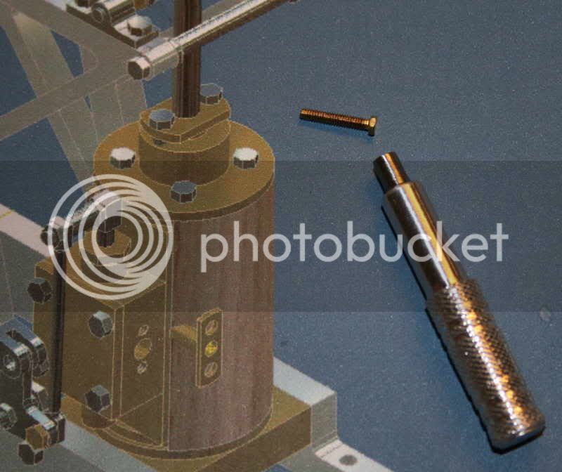
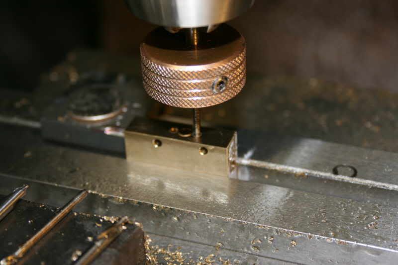
Well after looking around for a wrench for the small 2-56 hex head screws I have for this model I decided to make one.
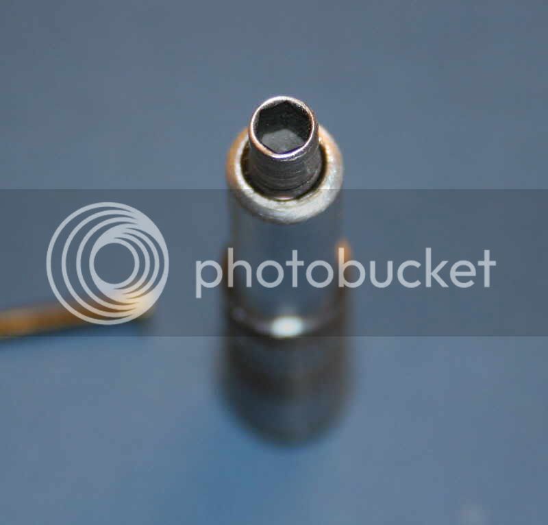
So today at lunch time at work (I get 30min lunch break). I quickly ate my lunch which left me about 15 min so I went out to the shop and knurled a piece of 3/8 dia aluminum and drilled and tapped a 1/4-20 thread in end ( the head of the small screws are the same size hex as the hex in a 1/4 set screw) and threaded in a 1/4-20 set screw and then turned down the dia and parted it off. Not bad use of my extra 15 min but don't give me grief about the knurl I usually do a better job but I was in a bit of a hurry.")
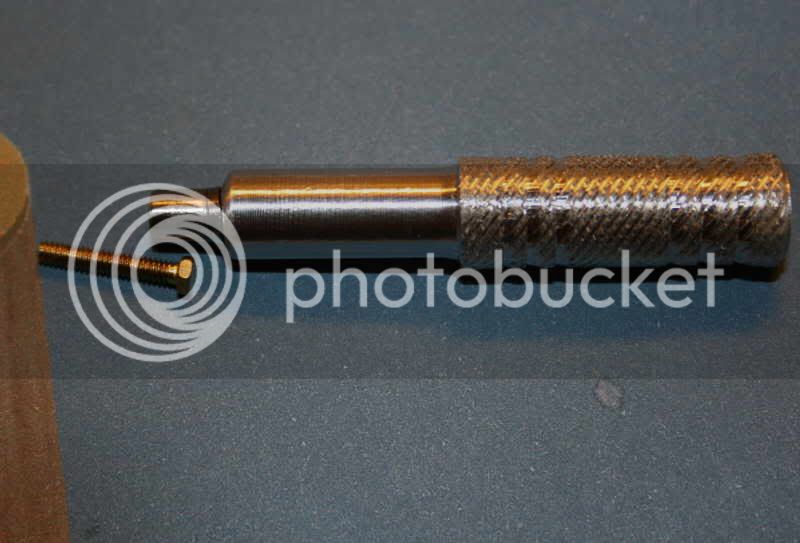
Now out to the shop to slow down and unwind :big:
So today at lunch time at work (I get 30min lunch break). I quickly ate my lunch which left me about 15 min so I went out to the shop and knurled a piece of 3/8 dia aluminum and drilled and tapped a 1/4-20 thread in end ( the head of the small screws are the same size hex as the hex in a 1/4 set screw) and threaded in a 1/4-20 set screw and then turned down the dia and parted it off. Not bad use of my extra 15 min but don't give me grief about the knurl I usually do a better job but I was in a bit of a hurry.
Now out to the shop to slow down and unwind :big:
doc1955
Gone
- Joined
- Aug 26, 2009
- Messages
- 1,261
- Reaction score
- 168
Well only had about an hour and half in the shop after work today.
Got a little done on the steam chest.
Sized up stock.
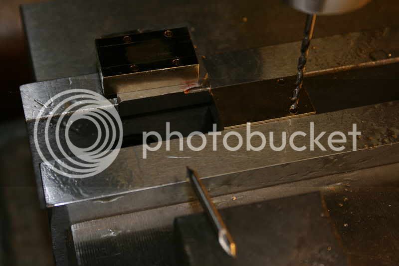
Drilled the 4 hole pattern in face.
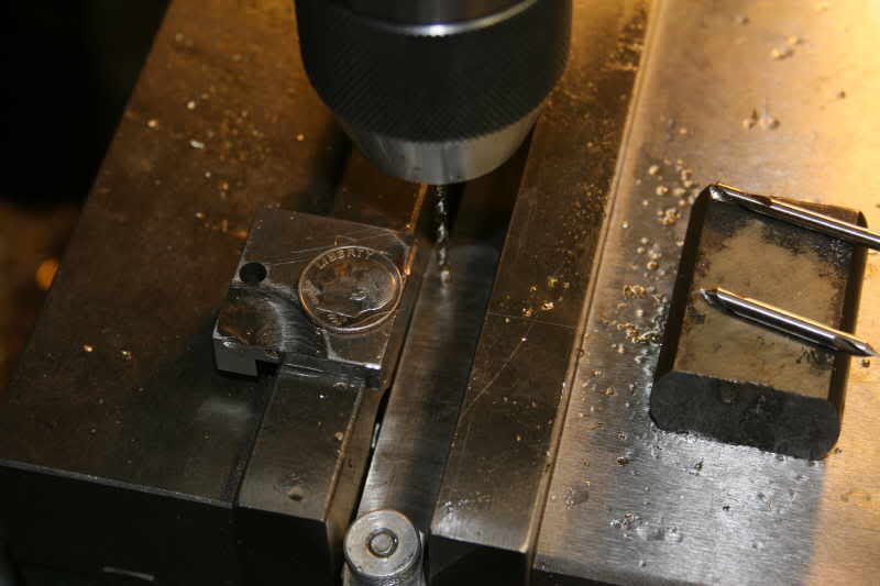
Set drill above parallel .022 to drill spindle hole don't want it going through the bottom.
Drill an tap side hole for steam manifold.
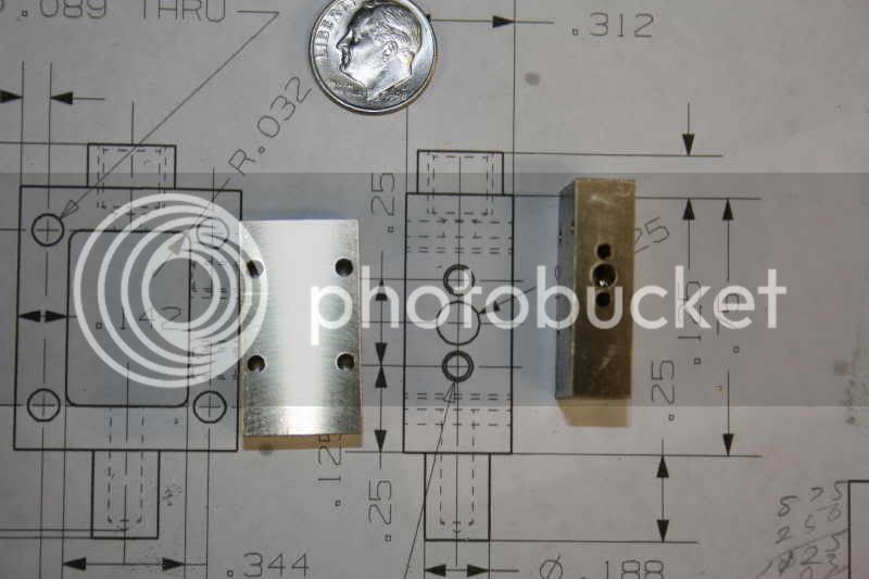
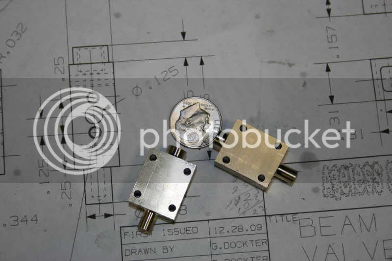
Parts so far. Now I need to decide whether to put them in the 4jaw on the lathe or use a boring head and reverse bore the 2 end diameters.
Got a little done on the steam chest.
Sized up stock.
Drilled the 4 hole pattern in face.
Set drill above parallel .022 to drill spindle hole don't want it going through the bottom.
Drill an tap side hole for steam manifold.
Parts so far. Now I need to decide whether to put them in the 4jaw on the lathe or use a boring head and reverse bore the 2 end diameters.
doc1955
Gone
- Joined
- Aug 26, 2009
- Messages
- 1,261
- Reaction score
- 168
I remember some posts about dialing in a square on the lathe in the 4 jaw so I put the video camera on while dialing in to turn the spuds on the steam chest. It's noisy at first didn't notice the furnace was running but it stops part way through. Anyway hope this helps those who have trouble dialing in square or rectangle stock on the lathe.
Once you've done it in this fashion a few times you get it down where you can do it in only a mater of a couple minutes.
[ame]http://www.youtube.com/watch?v=a7HhppYHwig[/ame]
Here the parts are after turning.
Once you've done it in this fashion a few times you get it down where you can do it in only a mater of a couple minutes.
[ame]http://www.youtube.com/watch?v=a7HhppYHwig[/ame]
Here the parts are after turning.
Doc,
Thanks for the tutorial on setting up your work in a four jaw chuck.
My learning curve has been has been vertical.
I am still making parts for my Shoptask, one day I will be able to spend time making an engine.
Thanks again,
Scott
Thanks for the tutorial on setting up your work in a four jaw chuck.
My learning curve has been has been vertical.
I am still making parts for my Shoptask, one day I will be able to spend time making an engine.
Thanks again,
Scott
Shoot, Doc. I missed this whole thread thinking it was a CAD discussion, judging from the first couple of posts.
(sorry)
Just went back and read through it.
I like the way you do your... everything! Flywheels, crank throws, main frame, rounding with the flycutter, all that stuff. Good pics and descriptions.
Keep it up!
Dean
(sorry)
Just went back and read through it.
I like the way you do your... everything! Flywheels, crank throws, main frame, rounding with the flycutter, all that stuff. Good pics and descriptions.
Keep it up!
Dean
doc1955
Gone
- Joined
- Aug 26, 2009
- Messages
- 1,261
- Reaction score
- 168
Well got a little done today.
I finished up the steam chest main housing.

Then I started the spindle for the steam chest.

Turned up spindle using live center and .25 dia stock material.

Then off to the mill to mill .124 square end.

Milling square using a 5c collet block.

Then drill and tap 2-56 hole after that back to the lathe to part off spindle.

Spindles in place in steam chest.
Next square up and size up stock for slide valve.

Tomorrow I'll work on slide.
I finished up the steam chest main housing.
Then I started the spindle for the steam chest.
Turned up spindle using live center and .25 dia stock material.
Then off to the mill to mill .124 square end.
Milling square using a 5c collet block.
Then drill and tap 2-56 hole after that back to the lathe to part off spindle.
Spindles in place in steam chest.
Next square up and size up stock for slide valve.
Tomorrow I'll work on slide.
doc1955
Gone
- Joined
- Aug 26, 2009
- Messages
- 1,261
- Reaction score
- 168
Well didn't get much shop time again today. In the time I did have I milled the small pockets in the slide valves and the slots in them for the spindle.

I used a process called plunge milling where as I took .010 per plunge until I got to the right width or depth of slot.
Here is a picture of my little shop aid to help me remember where I'm at with the table. I don't have a digital read out I go by the dials and this.

Basically just mad a small pointer and stick a scale with a magnet to the table works pretty good for me until
I break down and but a readout system. But for now this will do just fine.

Here are the valves done and in place the only thing left to do is during final assembly I will lap them flat with the main steam chest body right now they stick above the main body about .002.

Here ar the steam chests with the valve in place.
Now for the cover for the steam chest. I'm using aluminum.

Drill all the holes notice both parts are in vice. I'm using a piece of heavy paper on the movable jaw side to make sure both parts are clamped securely.

Here I have the 2 pined together and am milling part of the profile.

Another part of the profile.

And here they are completed.
Next time I get to spend in the shop I'll be working on the ecentric.
I used a process called plunge milling where as I took .010 per plunge until I got to the right width or depth of slot.
Here is a picture of my little shop aid to help me remember where I'm at with the table. I don't have a digital read out I go by the dials and this.
Basically just mad a small pointer and stick a scale with a magnet to the table works pretty good for me until
I break down and but a readout system. But for now this will do just fine.
Here are the valves done and in place the only thing left to do is during final assembly I will lap them flat with the main steam chest body right now they stick above the main body about .002.
Here ar the steam chests with the valve in place.
Now for the cover for the steam chest. I'm using aluminum.
Drill all the holes notice both parts are in vice. I'm using a piece of heavy paper on the movable jaw side to make sure both parts are clamped securely.
Here I have the 2 pined together and am milling part of the profile.
Another part of the profile.
And here they are completed.
Next time I get to spend in the shop I'll be working on the ecentric.
Similar threads
- Replies
- 11
- Views
- 1K
- Replies
- 11
- Views
- 779
- Replies
- 83
- Views
- 10K
- Replies
- 8
- Views
- 2K
- Replies
- 61
- Views
- 14K