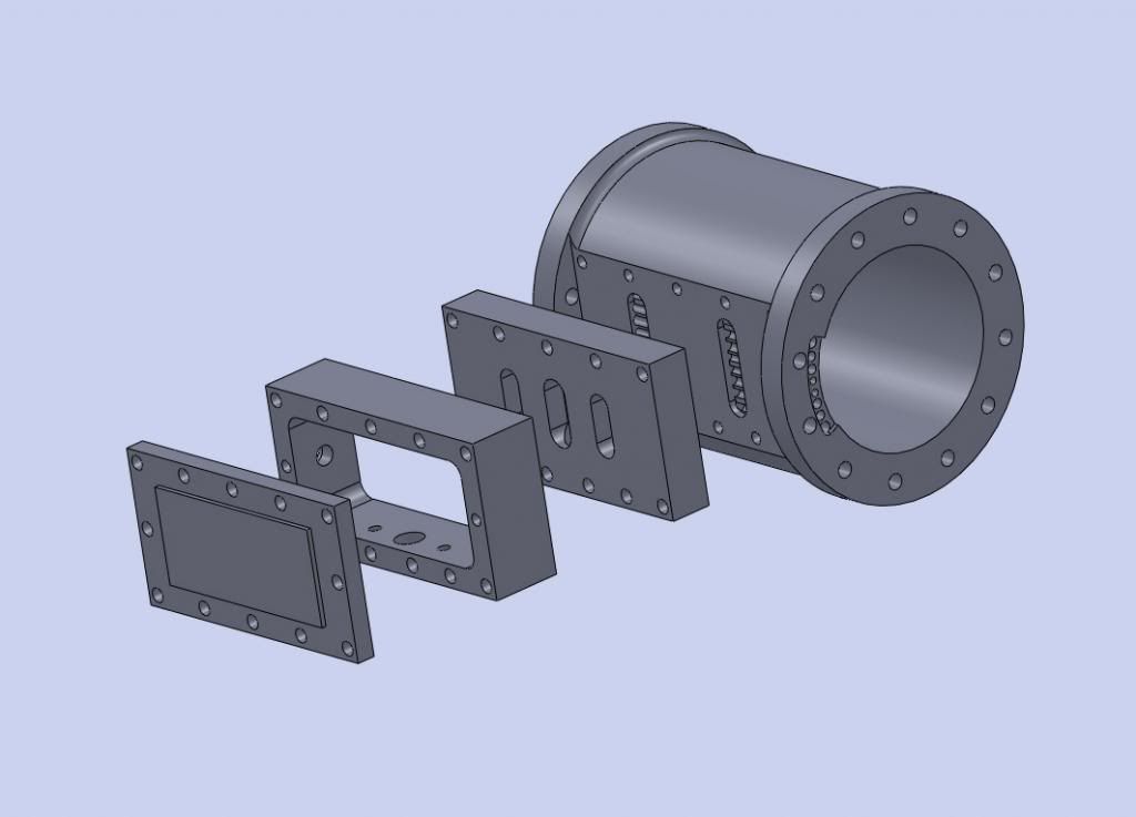
fabricated slide valve cylinder

Home Model Engine Machinist Forum

Help Support Home Model Engine Machinist Forum:

This site may earn a commission from merchant affiliate links, including eBay, Amazon, and others.

chucketn

Senior Citizen
Joined
Dec 17, 2009
Messages
1,326
Reaction score
167
Location
Near Jonesborough, TN
I'm looking forinfo/references/pictures, etc. to help me learn how to fabricatecylinders for slide valve type steam engines like the picture attached. I have several books onbuilding engines, and many downloaded engine plans, but none seem tocover fabrication of the cylinder. I could build a patern and castthem in aluminum, but I don't have a furnace yet.

Have you fabricated a slide valve steamengine cylinder? Do you have build pictures? A source for plans orbooks that detail methods?

Chuck

cylinder_1.jpg
 
Chuck,
This appears to be a Stuart #10 cylinder and if that's what you are shooting for I wouldn't bother fabricating, I would just mill it out of a solid block of C.I. or bronze. My approach to fabrication is to create a "casting", that is, I don't try to have any of the machined (or to be machined) surfaces survive the fabrication process without requiring finish machining. As for fabrication process, that would fill a book chapter and would depend upon the size of the fabrication and material used.

Most large fabrications I know of have been cylinders (and saddles) which have been fabricated from mild steel, either by welding or silver soldering (or both), then machined like a casting, with cylinders sleeved with cast iron or bronze and valve faces surface with cast iron. That's a lot of complications just to save going through the patterns and castings process. Attached is a photo of a smokebox saddle for a 6" diam smokebox for a locomotive I have under construction. This particular piece has proven to be quite a bit more difficult and time consuming than I thought and in hindsight I would have come out better had I just gone ahead and made a pattern and core box and had it cast somewhere. Smaller assemblies are better made from bronze and can be all silver soldered which is not as time-consuming as welding assembly and subsequent cleaning and machining.

To determine what bits you have to make to put together to make the assemblies is something else, which is difficult to describe here. You have to be able to look at the part and visually break it down into geometric sub-parts (rounds, flats, squares, rectangles, disks, shapes, etc) which can be individually cut or machined and then reassembled into the whole. Another consideration you will have is how to hold the bits together while it's being welded of soldered. I held my saddle together with screws for the initial assembly (silver solder) and those were removed, countersunk, and filled when subsequent welding operations were added.

To fabricate a cylinder, you normally start with a tube or sleeve, end face plates, and a valve block, and then add in bits to make bosses, pads, etc. That's what you #10 cylinder in composed of, a central tube, two end plates, a valve block, and a few bosses or pads. There's tons more that can be said about this but that's what comes immediately to mind.

SADDLE1.jpg
 
Last edited:
Harry,
I ment like that type of cylinder, not that exact one, even a simplified version would be fine. Closest I have come is from a french website. I think silver soldered brass or bronze is what I'm wanting.
Ideally I would be able to make several and build horizontal and vertical examples of this engine. Maybe even a twin.
When the weather warms a bit, I'll work on building a pattern and furnace.

Chuck
 
Harry, I meant like that type of cylinder, not that exact one, even a simplified version would be fine.
Chuck,
I understand, but I had to ask the question to get a feel for the scale you had in mind. Bronze would be best for smallish cylinders for several reasons. It machines and works easily, it solders well, it resists corrosion, and is a good material for cylinder and valve faces.

I found something in my archive that might interest you (or maybe discourage you, but I hope not.) This photo is of an example of a well-known model beam engine (The 1" scale Sanderson) that was built by a fellow in London entirely by fabrication. It shows what can be done with a little ingenuity. (Material is bronze. Photo by "Derek".)

SandCyl.jpg
 
Last edited:
Thanks Harry, and Jason. Now that's a lot to take in. My skills are not that advanced yet. Your examples do show what's possible.
I'm thinking of the old casting sets, or like the engine MrPete2222 builds in the video on you-tube.
I'm thinking simpler yet, closer to this one :

Chuck

Pg_26_Dbl_acting_Slide_Valve_Engine_assembled.jpg
 
Last edited:
Chuck,
That one would be pretty much what I described, four pieces - the cylinder tube, two end faces, and a valve block, plus a boss or two if you want. I see eight pieces in the stand and trunk guide.
 
Last edited:
Do I understand correctly, that the concave portion of the valve block can be made from bar/flat stock with a boring head?

Chuck
 
Yes boring head or large milling cutter, whatever matches the OD of the cylinder.

If you are only going to run on air you don't really need to use flanges at the end as the void is only for insulation or to save material on larger cylinders.

J
 
Yes, or a fly cutter, and provided the cylinder tube isn't too big you might also be able to do the job in a 4-jaw chuck.
 
Why silver solder?
Bill,
If I knew that the engine would only ever be run on air then soft solder would do the job. I use soft solder on some steam fittings, and IME it will take most machining stresses, but soft solder begins to lose tensile strength quickly beyond 175F and even at 20psi steam is still around 260F. Granted it's a stretch to say that any surface in the model would get to 260F but I'd rather not have my model come apart (or come loose) unexpectedly so I would silver solder. At the sizes being discussed here silver soldering temp is just a minute or so of heating away from soft solder temp.
 
Hi Chuck,
Another option that involves no casting, no soft soldering, no silver soldering, no brazing and no 'unobtanium' glue is as follows.

Turn up your cylinder out of your chosen material. Mill a flat on to the one side where you want the valve chest to live. Make an intermediate block which carries your inlet ports and exhaust port. Make up your hollow valve chest (which carries your valve slide). Make up your valve chest cover. Sandwich all parts together with a series of studs screwed into the cylinder flat face and use gasket material between each mating face.
I think that this is the sort of idea you were after in your original question.
The following picture does not show the valve rod, valve slide, cylinder end covers or piston.
I do however hope that it is helpful.
Cheers, Norman.

Assem1Builtupvalvechest.jpg
 
Thank you, Norman. Your picture makes it much easier to understand the valve action as well as giving me more ideas on construction of this type of cylinder.
In this picture, what is the purpose of the center slot in the block next to the cylinder? Is the exhaust port connected to this?

Chuck
 
In this picture, what is the purpose of the center slot in the block next to the cylinder? Is the exhaust port connected to this?

Chuck

Hi Chuck,

You are correct, ...the two outer slots are the steam passages to and from the matching ports on the front and rear of the cylinder. The centre slot is for the exhaust and exits out of the bottom of that intermediate block. Steam inlet is through the bottom of the open sided valve chest, although this could be sited on top or even through the valve cover, whatever your preference.

Cheers, Norman.
 
Norman,
I will be using almost the same "sandwich" construction technique on the cylinders (cast iron) for a 7.5"ga locomotive I have under construction. The castings were uncored and they were to be machined in the conventional way (steam passages milled & drilled.) However machining exposed a blow hole in one cylinder and contaminated metal in the other, both in the valve face area, so the solution will be to mill away the bad iron and build it back. The upside will be that the steam passages will be easier to machine and I expect will result in improved steam flow and distribution.
 
Hi Chuck - just come into this thread - asleep as usual :rolleyes:

Theres also the JB weld 'method' which I've used successfully before (I think Jason tried it on his Benson engine) - no heat, no distortion or annealing and very very strong. Totally oil proof and even if you did decide at a later date to run on steam good to 550-600F according to the spec. (I repaired a Stuart Twin Victoria cylinder with it years ago which ran on steam (wet) for many years without failure)

Personally now I wouldn't use any other method as you can machine all the parts more or less exactly as you want them before bonding without that need to machine after and even if there is a need its well strong enough to resist the likely small cutting forces involved.

There's a build here you might want to peruse too which shows the cylinder on the Waller engine being made.
http://www.homemodelenginemachinist.com/f31/table-engine-tale-15630/
Hope this helps a liitle more

Regards - Ramon
 

Latest posts

Back
Top