Fabricated Crank Shaft.

Home Model Engine Machinist Forum

Help Support Home Model Engine Machinist Forum:

This site may earn a commission from merchant affiliate links, including eBay, Amazon, and others.

Tony Bird

Senior Member
Joined
Feb 20, 2011
Messages
825
Reaction score
901
Location
Cardiff, South Wales, UK
Hi,

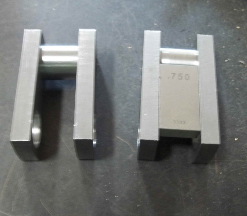
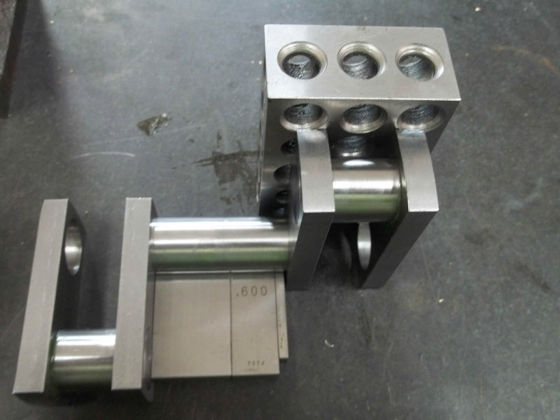
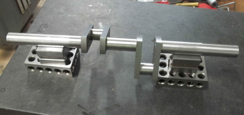
I hope the following photographs explain how a crank shaft can be fabricated my glueing (Loctite) and pinning.

Regards Tony.

IMG_0987 LR.jpg


IMG_1004 LR.jpg


IMG_1005 LR.jpg


IMG_1009 LR.jpg


IMG_1012 LR.jpg


IMG_1014 LR.jpg


IMG_1016 LR.jpg


IMG_1019 LR.jpg


IMG_1020 LR.jpg


IMG_1021 LR.jpg


IMG_1024 LR.jpg


IMG_1022 LR.jpg


IMG_1025 LR.jpg
 
Hi Tony,
Reading with interest and awe.th_wav
Will Monkey See,Monkey Do next crankshaft. All my single throw crankshafts were failures.
 
Hi Tony
Three weeks ago I machined crankshaft exactly this way for my new 4 cylinder engine.
Only difference , instead pinning parts i TIG welded them together.
Kadora

2014-12-16-1018.jpg


2014-12-18-1022.jpg
 
I'm jealous as I have no room in a small workshop for TIG or really much other than a propane bottle.

I've 'downsized' for old age and infirmary(?)

However, the more usual silver soldering requires a little space so that the solder has room to 'wick'

A lot of people will put a cut on the pin to assist this flow . This wicking comes to the fore when one is tubing a boiler.

My two pennorth, of course

Greetings

Norman
 
For both Loctite and silver solder (silver braze for our US cousins) require a working gap of approximately 0.002" to wick into to work correctly. This cannot be achieved and everything kept in line and square together without a further operation.
Keep the shaft at the correct size, but make the hole it will be fitting into 0.002" larger (or somewhere close).
Where the actual rod fits into the hole, put on a small straight knurl (even one that has only just start to cut will raise the size by a couple of thou. You can then force fit the parts together and they will hold themselves together enough for all the other work to be carried out on them.
When this is done, the knurled area is full of tiny slots going through the assembled parts, which allow both Loctite and silver solder to flow through and do it's job correctly.
I have never had anything come loose whilst using this method.

John
 
When fabricating a crankshaft, by whatever means, how do folks get a neat finish to the cut out of the inside webs?

I've tried hacksawing, also using an endmill followed by filing the cut off areas smooth, but my filing is obviously not very good as I always seem to get file marks on the webs. Tried using tape to protect the webs (the thinnest being the sticky brown parcel tape), but then I can't get everything flush.

Dave
The Emerald Isle
 
I find that 3 corner files have a slight convexity that help filing a spot in the center of a plane without bugaring (technical term) the area around.
 
I did one for my Joy Valve engine using loctite 620 and no pins. The rods are .75" diameter so lots of glue surface. It is a 2-cyulinder engine so two throws.

When I did the crank pins I used gauge blocks clamped between the webs to ensure that the webs are parallel, and had the edges of the webs laying on a surface plate to ensure that the rest of the assembly rods would line up.

large.jpg


large.jpg


Finally dry assembled the side rods to verify that everything was straight before gluing.

large.jpg


DI showed 2.5 thou total runout over a 14" crankshaft
 
Hi,
What is the loctite you are using? I want to bond a piece of phosphor bronze to a brass shaft and then machine it to make a gearwheel. The material you are using should do the trick.
Regards,
Alan C.
 
When fabricating a crankshaft, by whatever means, how do folks get a neat finish to the cut out of the inside webs?

I use angle grinder kept in special holder.
Cutting surface is not perfect but acceptable.
 
I have been trying unsuccesfully for some time to make a double throw crankshaft for a twin cylinder steam engine. Crankshaft diameter is 1/8th. inch. Webs are also 1/8 thick, throw is 1/4". I have tried drilling slightly undersize and pressing the shaft and web together, unsuccesfull because it ended up out of square. Used loctite did not hold, used JB Weld did not hold, tried silver solder, would not flow into joints, tried epoxy also did not work. I do not have the skills to turn the crankshaft as a solid piece, also do not have CNC capability. I have not tried pinning as described earlier in the thread, I guess I would have to pin with 1/16th rod. The other parts of the crankshaft have been made from steel rod on all of the other attempts except one in which I used aluminum for the webs thinking it would pressfit easier.
Any other suggestions for working on this project in this scale would be appreciated.:mad:
On the happier side I just completed a steam engine with rotary valve -my first attempt to use rotary table on the mill - suprise the engine runs fairly well.
 
Hi,

I have been trying unsuccessfully for some time to make a double throw crankshaft for a twin cylinder steam engine. Crankshaft diameter is 1/8th. inch. Webs are also 1/8 thick, throw is 1/4". I have tried drilling slightly undersized and pressing the shaft and web together, unsuccessfully because it ended up out of square. Used loctite did not hold, used JB Weld did not hold, tried silver solder, would not flow into joints, tried epoxy also did not work. I do not have the skills to turn the crankshaft as a solid piece, also do not have CNC capability. I have not tried pinning as described earlier in the thread, I guess I would have to pin with 1/16th rod. The other parts of the crankshaft have been made from steel rod on all of the other attempts except one in which I used aluminium for the webs thinking it would press fit easier.
Any other suggestions for working on this project in this scale would be appreciated.
On the happier side I just completed a steam engine with rotary valve -my first attempt to use rotary table on the mill - surprise the engine runs fairly well.


With such a small crank shaft I would try silver soldering. To make space for the solder I would use a triangular file to make 3/4 shallow slots in the holes in the webs.

Regards Tony.
 
Hello again,

I have just finished making the split big end to fit on to the crank shaft. Members might be interested in how the big end was reduced in width and a relief step turned on it. I hope the photographs explain the technique used, if not please ask. Shellac melts at 84C and can be dissolved with methylated spirits (Ethanol) .

A Happy and Healthy New Year to the members of HMEM.

Regards Tony.

IMG_1108 LR.jpg


IMG_1109 LR.jpg


IMG_1110 LR.jpg


IMG_1113 LR.jpg


IMG_1114 LR.jpg


IMG_1116 LR.jpg


IMG_1118 LR.jpg


IMG_1122 LR.jpg


IMG_1123 LR.jpg
 
My thoughts.

I use Loctite 620 for slip fit joints, and it works quite well. But the total surface area of the joint determines how strong it is. If the shafts were 1/4" diameter the area and hence the strength would be 4x better than with 1/8".

If you were to use 1/4" rods with the center turned down to 1/8", and drilled the webs 1/4", it might work for you. Assemble the sections with only one glue joint at a time. To assure being square, you can use gauge blocks and/or machinist squares to line up and space the elements properly.

If you can increase the web thickness some that can help too.
 
Tony: Nice idea for the big end. It looks like that is a No.10. I built one 35+ years ago and I can't remember how I did mine.
It also looks like you have the flywheel on the opposite side as mine. It took me a while to figure out what was different. I have attached a picture of mine although it needs a good cleaning! Had me wondering if I built mine backwards (wouldn't be the first thing I built backwards!)

John

DSCN5334.jpg
 
Hi John,


It also looks like you have the flywheel on the opposite side as mine. It took me a while to figure out what was different. I have attached a picture of mine although it needs a good cleaning! Had me wondering if I built mine backwards (wouldn't be the first thing I built backwards!)

No yours is the right way around, I am building the model for a friend and he wanted the way it looks and fitted with two flywheels. I have a Stuart 10H built to the drawings which is coupled to a PMR dynamo.

Regards Tony.

IMG_0739 LR.jpg
 
On the last one i made,i press fit the pins into the webs.The pins are turned to a shoulder and correct dim.The turned sections are are a press fit for half the length and undercut 3 thou for silver solder penetration for the first half.The sub assys are cleaned up and then assembled to the main shaf.Locked in with grubscrews in the correct location/orientation.Again the shaft is undercut at the web faces for the silver solder to wick.I do all the cleaning up i can before removing the waste sections.Only failure was not prepping enough for the silver solder.Works for me
 
Hi Tony.

A MasterPiece by a Master Craftsman.th_wav

Reminds me of the Ingersoll-Rand USA , Model ESH 12 x 9 Single Stage Air Compressors I erected and start up in the field all over S.E. Asia in the 60s------70s. Painted Post Plant used to make this machines. These machines will run forever if well maintained. Spent some time there and stayed at Howards,Corning.
 
Back
Top