Enco (Rong Fu RF30) Mill/Drill Conversion

Home Model Engine Machinist Forum

Help Support Home Model Engine Machinist Forum:

This site may earn a commission from merchant affiliate links, including eBay, Amazon, and others.
Just a quick update. The DB25 cable was delivered a couple of days ago. I got the motors, the Gecko controller, cables and the power supply all hooked up. Loaded up Mach3 and got everything configured. The steppers all respond and move correctly to the Mach3 commands. Even loaded up the G-Code file to print my name and ran it. Unfortunately, I still haven't received my X & Y timing belts (Aarrgghh!). So, even though the motors spin, the table doesn't move... Wish I'd ordered the belts sooner. Now that the conversion is virtually done, the waiting is killing me!
Chuck

Chuck! thats great to hear.

Quick note: when you get the belts on remember that the arrow keys on the keyboard are which way the tool is supposed to move, not the table. That means when you hit the left arrow the table should move right. When you hit the arrow to move toward you, the table should move away from you. When you arrow left and the table moves right its the same as the tool moving left.

Thanks, Steve, I had to double check, but turns out I did have it right. I can tell from the direction the motors are turning which way the table will move.

Chuck
 
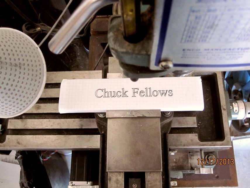
Got the belts today. Here's a picture of the first job...

IMG_3165_zpsb8f74203.jpg


Video is still uploading to Youtube... will post the link later.

Chuck
 
Thanks, Chuck, here's the video...

[ame]http://www.youtube.com/watch?v=mcI9PjygQRY[/ame]

Chuck
 
Thanks, Steve, Rick. I think I ruined the only felt tip pen I have!

So, I want to do some profile cutting in 1/4" aluminum plate (I'm guessing it's 6061) using a 1/8" Kyocera, 2 flute solid carbide bit. My milling spindle will only do about 2500 RPM. How fast should I feed the work and what depth of cut would be best? I've currently the feed rate set at 12 inches per minute. I've looked at several web pages and they start talking about surface feet per minute, inches per tooth, and other terms that I just don't understand.

Chuck
 
Feed rate stuff? I only remember some of it from running CNC 13(?) years ago. I'll bet you have a good enough feel and ear for it from all the milling you have done. I only did it in one material so I only had to change RPM and FPM based on cutter diameter.
 
Chuck, the aluminum profiling I have done was with a 2 flute carbide bit at 1800 rpm. At the time that was the max spindle rpm. I cut .008 deep at about 1/3 the tool width. The problem you are going to run into is the tool will try to gum up(I assume you aren't running a coolant). Stand by with a can of WD-40.

With Mach it's difficult to stop and start again, but if your tool gums up you will probably break it. The low RPM helps to keep the tool clean because of less heat generation.

maury

Thanks, Maury. I have plenty of time to make my parts, so speed isn't an issue. I'm mostly interested a good finish and keeping the cutter sharp and clean. If low RPM's and feed rates, do the trick, I'm all for it!

Chuck
 
Hi Chuck nice job
tou might find these usefull
http://en.wikipedia.org/wiki/Speeds_and_feeds#Formula_to_determine_feed_rate

http://its.foxvalleytech.com/machshop3/speedcalc/feedratecalc.htm

as for the cooler I really sugest AL9 a real aluminium cooler and it smells good
if ever you do manage to get some aluminium to stick to your mill, not a big issue
go to any hardware store by some muriatic acid "cement cleaner" and put your mill in it
it will get of of htere like brand new
be carefull with the handling it's verry corosive
 
Thanks, Steve, Rick. I think I ruined the only felt tip pen I have!

So, I want to do some profile cutting in 1/4" aluminum plate (I'm guessing it's 6061) using a 1/8" Kyocera, 2 flute solid carbide bit. My milling spindle will only do about 2500 RPM. How fast should I feed the work and what depth of cut would be best? I've currently the feed rate set at 12 inches per minute. I've looked at several web pages and they start talking about surface feet per minute, inches per tooth, and other terms that I just don't understand.

Chuck

Aluminum I cut .025 deep steps at 30IPM with WD40.


Chuck! Have you calibrated the screws yet. By that I mean set an indicator against the table and have Mach move the table say .050 and see if it really moves .050. I have an indicator with a 2 inch stroke so I check mine over one inch.
 
Feedrate does matter on CNC, its not like on a manual machine where you can just crank a little faster or slower. But its pretty simple.

All materials and tool combinations have a best value for Surface Feed Per minute. For steel and normal HSS tools its about 75 to 100. For Aluminumits more like 250-300. Carbide tools can double those values. SFM is simply the 'rim speed' of the tool- Higher RPM makes it go up, larger diameter tool makes it go slower. All you need is material and tool dia and you can find SFM.

Chip Load is how big a chip you want each tooth to take, numbers like .001 are Ok on 1/4" or bigger tools, as small ass .0001 is not unreasonable for tiny cutters. Just multiply your SFm by the chip load. Obviously Moving a tiny cutter through material at several inches per minute will quickly break the tool, and running to slow will just cause your chips to roll around and around in the cut, scoring the finish and dulling the tool. When its right teh chips just flow off teh work and the surface finish is great

Both calculations are simple math, and there are lots of tables and calculators around. The Mach wizards have several calculators.

It matters if you want decent, clean cuts.
 
Looks good! ImageUploadedByModel Engines1394368354.113161.jpg I have a cncmasters rf31 conversion and when I saw your brass ballnut holder for the short axis I laughed. I have the same one holding my ballscrew, what a pain it was to remove! The oem jb welded it in for a more solid connection since only one bolt holds it. They should have had it held by 2 pins and a single bolt so when you torque it, it doesn't twist. Looks good though. I bought a quill dro for mine, yet to put it on.ImageUploadedByModel Engines1394368552.318961.jpg
 
Chuck I have an Enco mill drill, I think it's very similar to yours. Can you tell me who has a conversion kit available. Did you change over to Ballscrews? I currently have a Zentools 3axis machine running with Mach without a spindle and would like to convert the Enco. Any input would be appreciated. Thanks. JerryKnox


Sent from my iPad using Model Engines
 
Chuck I have an Enco mill drill, I think it's very similar to yours. Can you tell me who has a conversion kit available. Did you change over to Ballscrews? I currently have a Zentools 3axis machine running with Mach without a spindle and would like to convert the Enco. Any input would be appreciated. Thanks. JerryKnox
Sent from my iPad using Model Engines

Hi Jerry,

I did convert over to SFU1605 ballscrews and nuts. The ballscrews were unmachined and I had to turn down a 1/2" length on each end to 1/2" diameter so I could attached machined steel extension shafts to each end. I custom made the ballnut attachment fixture for each axis. The steppers I used were Nema23, 425 Oz In. The motors drive the ball screws through XL timing belts with a 1:3 gear reduction. For the stepper controller, I used a Gecko G540 4 axis controller.

Chuck
 
Thanks Chuck for the quick reply, do you have any info as far as measurments and suppliers? I also have the Gecko 540 and it works well. Are the Rong Fu and Enco the same machines, just different suppliers? I had a job in Springfield Mo. once and did go through the Grizzly Store, Quite the (Toy Store) I live near Chicago and they use to have an Enco outlet here. I bought the MillDrill from a private party. Im pretty new to this website so I have even more to learn.I keep seeing the not so Happy Face keep banging his head against the brick wall ( I can relate ) Great NAMES show this year, Talked to Dale Dietrich and got his plans for the T fitting engine, and Gbritnell had plans for a beautiful V-Twin. I heard this is a desease called Iron Defeciency. Thanks again and any inof great help Jerry
 
Chuck,
I have enjoyed your post on the mill conversion and your many other build posts and projects. I have been contemplating converting my knee mill to cnc. Like you I am not worried about high speed cutting and can always upgrade to bigger motors someday. Did you have a particular plan you followed or web site that was most helpful? I have been browsing and studying for a couple of weeks, there is a lot of info out there, but I haven't found anything like a simple block diagram to follow. Any advice from someone who has been there done that?
Looks like your conversion was a great success.
Thanks for your time and for all of the posts that we have to learn from.
Mike Nay

Thanks for the compliments, Mike, much appreciated. Like you, I did visit a number of websites prior to and during my conversion. None stand out in my memory as being a one-stop-goto reference although Bob Warfield's website, www.cnccookbook.com has a lot of good information. I also started a build thread on CNC zone and got some good feedback there. Unfortunately, there are a lot of different views out there and it can be difficult to sort out the good information and determine what will be required for your own application.

One of my overriding concerns was not to make any modifications to the mill that couldn't be reversed. I wanted to be able to easily convert it back to its original, manual operation later if needed.

It turns out that the Nema 23, 425 oz in, 3 amp stepper motors were more than adequate for my conversion. They have a pretty high inductance, so won't run as fast as some others, but have plenty of torque. I originally used a 20 tooth timing pulley on the X and Y motors and 60 tooth pulleys on the lead screws but just recently I changed over to 40 tooth pulleys giving me a 1 to 2 ratio. This speeded things up by 50 percent and I still seem to have plenty of torque.

The ball screws I bought were SFU1605 from China. I bought them with unfinished ends to save on cost. Although they are hardened, I was able to machine them in my Logan 11" lathe using (sharp) carbide inserts. Installing the ball screws is the most tedious part. You have to make sure that the ball nut is in perfect alignment with end bearings so they turn freely and there is no binding or bending of the leadscrew. I had to depend on some shimming, using trial and error, to get things in alignment. And, of course, you have to eliminate any end play in the lead screw. I replaced the thrust bearings with angular contact bearings although I'm not sure that was really necessary.

So far I've been very pleased with my results. It's very accurate and, even though I'm extremely conservative on cutting speeds and depths, it's fast enough for me.

If you're like me, you probably are focused on the mechanical aspect of the conversion and haven't thought much about the electronics or software considerations. Those items will wind up costing a lot more than the steppers, ball screws and other mechanical parts. For starters, I decided to use the Gecko G540 stepper controller. At $260 (on ebay) it's pretty expensive but it was well worth it. It's very robust, easy to configure, and seems to be relatively bullet proof. My 24 volt, DC power supply was under $40, but if you decide to go with 48 volts or higher, the cost will be over $100 unless you are a better shopper than I am. And, of course, you'll need a desktop computer with a parallel port if you plan to use Mach 3. I bought a used one for about $75.

That brings us to the software. You mostly need three pieces of software, CAD, CAM, and the G-Code translator and, the biggest problem is, they have talk to each other. That basically means the CAD program has to be able to create a file format that the CAM program can read. And the CAM program must create a G-Code file that the translator can read. And, while there are standards, there are many standards, particularly if you get into full 3D, contour type CNC. I haven't ventured into the murky waters of full 3D and probably won't.

Starting at the end, I bought a Mach3 license for about $160 and have been eminently pleased with it. I still haven't learned all the ins and outs, but it was pretty easy to get up and running. You'll also need a CAD program to do your drawings. I use Visio for all of my 2D drawing and, since it will create DXF files, it works fine for me. That brings us to the CAM software, which is a real bucket of worms. It's by far the most complex part of the CNC equation and potentially the most expensive. I couldn't find any free CAM software that was satisfactory so I settled for CAMBAM. This was $149 and seems to be popular in the hobbyist community. You can download a fully functional copy of it to play with and it's free for the first 40 sessions. It's pretty intuitive and quick to learn the basics, especially for 2.5D CNC. 2.5D CNC means you can do 3D machining, but only 1, two-dimensional surface at a time, although you can string them together end to end as long as they are in the correct order. CamBam will do 3D contouring using 3D printer input files (STL), but will not handle full on 3D CAD files such as IGES or other, more complex 3D file formats.

This may be information you already have but thought it might be interest.

Chuck
 
Last edited:
Back
Top