- Joined
- Mar 9, 2010
- Messages
- 597
- Reaction score
- 704
Got started on the linkages for the parallel motion part of the mechanism, which guides the piston rod in a straight line from the end of the main beam.
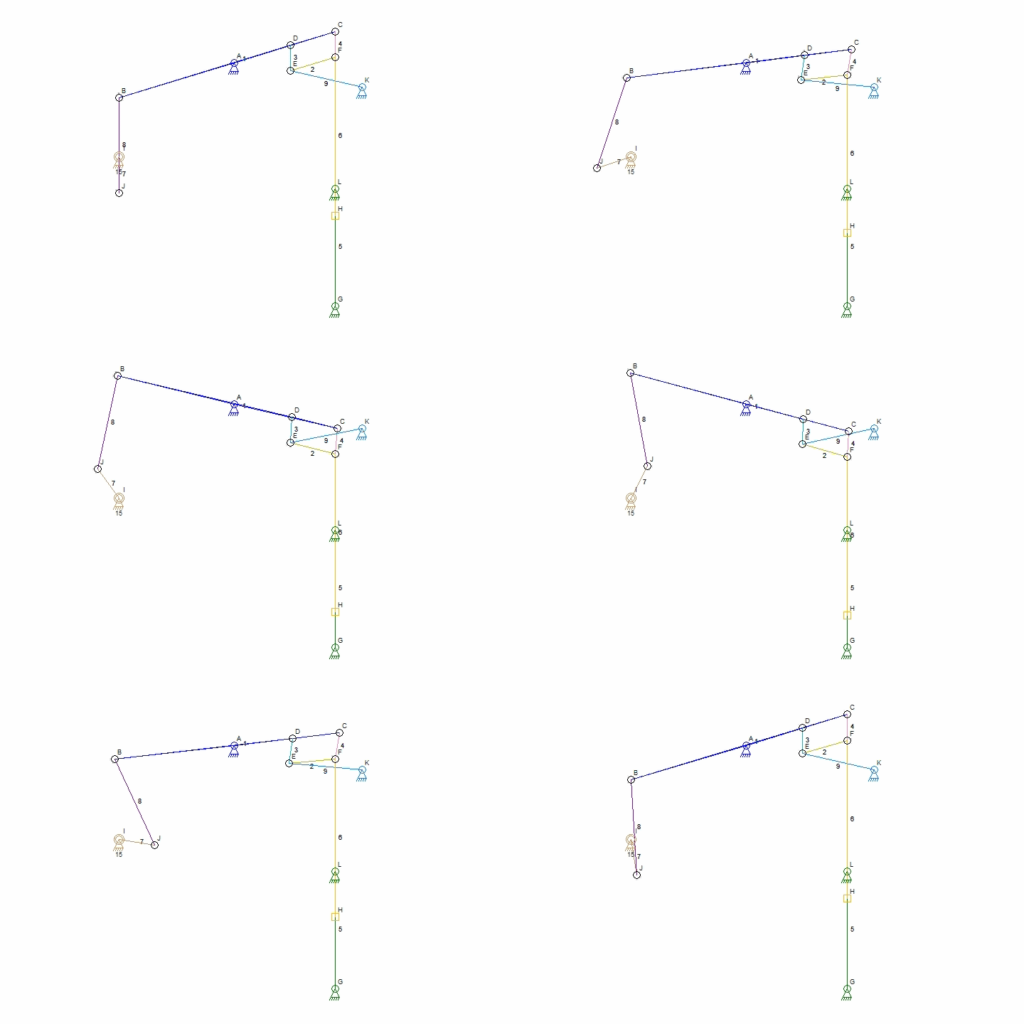
Here is a diagram of how the linkage works (thanks to wikipedia). The parts I am making now are labeled D-E, E-F, and E-K on this diagram. The bushing is what holds it all together at point 'E'.

The parts for this are pretty straightforward, just a lot of them. To start out I'll make the link bars and the bushing that connects them:

The bars will be pieced up from 3/8" dia. ends and 3/16" dia. rod. Since there are 12 link bars altogether it is definitely a case for mass production. Started with 3 lengths of 3/8" round steel, each long enough to make 8 ends. Drilled a 0.191 hole down the length of the rod, and then cross-drilled and tapped a series of 3/16-40 holes along the side (center drilled first, or main drill would skate off the curve):

The ends were then cut off, 0.200 thick. Made the rods from 3/16" bar:

and threaded/soldered the ends onto the rods:

Once all those were made (lot of the little buggers!), made the center bushings from 3/8" rod. The ends were turned down and shoulders threaded at the ends to hold an 8-32 nut:

Here is the first set together, showing the order the rods fit on the bushing and where the piston clevis will go in:

and both:

Next up is to make the shoulder bolts/nuts for the assembly, and get the parts hung on the beam. After that, need to make another support column set to hold up the forward link (at point 'K' on the diagram above).
Here is a diagram of how the linkage works (thanks to wikipedia). The parts I am making now are labeled D-E, E-F, and E-K on this diagram. The bushing is what holds it all together at point 'E'.

The parts for this are pretty straightforward, just a lot of them. To start out I'll make the link bars and the bushing that connects them:

The bars will be pieced up from 3/8" dia. ends and 3/16" dia. rod. Since there are 12 link bars altogether it is definitely a case for mass production. Started with 3 lengths of 3/8" round steel, each long enough to make 8 ends. Drilled a 0.191 hole down the length of the rod, and then cross-drilled and tapped a series of 3/16-40 holes along the side (center drilled first, or main drill would skate off the curve):

The ends were then cut off, 0.200 thick. Made the rods from 3/16" bar:

and threaded/soldered the ends onto the rods:

Once all those were made (lot of the little buggers!), made the center bushings from 3/8" rod. The ends were turned down and shoulders threaded at the ends to hold an 8-32 nut:

Here is the first set together, showing the order the rods fit on the bushing and where the piston clevis will go in:

and both:

Next up is to make the shoulder bolts/nuts for the assembly, and get the parts hung on the beam. After that, need to make another support column set to hold up the forward link (at point 'K' on the diagram above).
Last edited:


![DreamPlan Home Design and Landscaping Software Free for Windows [PC Download]](https://m.media-amazon.com/images/I/51kvZH2dVLL._SL500_.jpg)


![MeshMagic 3D Free 3D Modeling Software [Download]](https://m.media-amazon.com/images/I/B1U+p8ewjGS._SL500_.png)


