Double-Acting Twin Beam Engine Build

Home Model Engine Machinist Forum

Help Support Home Model Engine Machinist Forum:

This site may earn a commission from merchant affiliate links, including eBay, Amazon, and others.
The bar looks to be a Circle brand, solid carbide with steel head. I have seen them on Ebay and also you can buy them direct from several Circle distributiers here in the US. Great tools.
 
Hi Dave,

I got that boring bar and a couple other items from a friend in my archery league that was a retired machinist. It has C.M.C. USA on the side. It is a very nice bar, quite rigid, and takes only a small hole to start boring in. Not sure where to get one, have seen simaler ones in catalogs like McMaster-Carr, Enco, Graingers, usually for a steep price - tough to find a smaller diameter one.

The quick-change tool rest I bought from A2Z Corp - they make a bunch of aftermarket Sherline parts (also got the longer z-axis column for my sherline mill). Really like the quick change setup - have a number of the tool holders that I leave set up with left/right/center cutters, cutoff bar, and boring bar. Nice thing is that the height adjustment stays with the tool holder, so no need to reset the height every time. The one thing I did on there rest was re-mill the bottom surface - they sent it fairly rough, so it would not stay in place, kept rocking/turning under pressure. In their instructions it said to put a piece of paper underneath to prevent that - instead, I remilled the bottom flat, with a slight hollow in the middle, so it would grip properly around the edge when tightened down.
I also got a set of larger-shank tool holders that take replaceable inserts to use with them. Very handy.

Another real handy item are the welders parallel clamps - they are Kant-Twist clamps, in the two smaller sizes. Come in real handy for holding multiple parts together to place into the vice. Grip really well, dont twist parts out of alignment when tightening, and also have a groove on one side of the block that let you grip round stock.

Some of the other items, like the tailstock die holder, are home made - got info on that one from others in the forum, very handy. If you dont want to cut morse tapers, you can get blanks in alum. or steel from places like LatheCity.

Chris

Hi Chris

Thanks so much for your very detailed response, I went on Ebay after reading your post and there are many small boring bars on there, I also had a look at A2Z very nice equipment, I'm currently offshore working but will be placing an order once I get home, thanks again.

Dave
 
Time to make the valve crank assemblies, to transfer the horizontal motion of the bar from the eccentric to a vertical motion to move the slide valve. Here are the parts to be made:
scan_072.jpg

Starting with the crank bases, from 1/2" square bar stock:
IMG_3450a.jpg

First drilled 3/16 for the cross bar, then milled around that to leave a boss:
IMG_3458a.jpg

and milled out down to the base. Then flipped it over, and did same to other side:
IMG_3461a.jpg

And a couple passes on the sides to taper them
IMG_3463a.jpg

and milled out the centers for a little more style...
IMG_3469a.jpg

Drilled the bases for the mount holes (#43), then started on the horizontal crank arms. To make holding/aligning in the vice easier, made all 4 in one bar to be separated later. Started by drilling the 3/16" holes for the crossbar in one end and the 0.780 holes in the other for the clevis, and then started milling down between the larger holes:
IMG_3475a.jpg

Leaving the 4 arms to be sawn apart, and tapered on the sander and file:
IMG_3476a.jpg

Simaler steps with the 2 vertical crank arms, except these will have a slot in the arm so that an adjustable link can be used. This will allow for adjustments in the length of the throw to fine tune the valve movement distance. The adjustable link will be made later. For now, drilled the 3/16" crossbar holes, and rows of smaller holes for the slot.
IMG_3482a.jpg

These smaller holes were joined up with a jewelers saw and smoothed out with flat needle files:
IMG_3484a.jpg

Then, milled down the arms on both sides
IMG_3485a.jpg

sawn apart and the ends rounded with files:
IMG_3488a.jpg

That just left the linkage bars. Endcaps were made by crossboring some 1/8" holes halfway through some 3/16 rod, and rounding the top ends, and boring 1/8" holes in the bottom ends.
IMG_3477a.jpg

The middle caps, to connect the valve rod to the linkage, were made in a simaler way, except the cross hole goes all the way through, and the tops were filed to an acorn shape. These middle caps will not be soldered to the cross bar, but will allow the bar to rotate.
IMG_3478a.jpg

The endcaps were then soldered onto lengths of 1/8" rod, with the middle cap slid into place, to make the final linkage bar assemblies, shown to the side of the cylinders below. Still need to make the clevises to attach them to the cranks, and solder the middle cap to the valve rods..
IMG_3492a.jpg

Starting to look like an engine finally! Been doing some sketching to decide on the decorations for the main beams and the inserts for the bars to link to the valve eccentrics (will be way too long to just use thin bar, so will be two bars with an insert between. More on that to come...
 
Time for some fiddly-bits - the clevises for the valve cranks. There are 4 needed to connect the vertical rods to the cranks, and 2 more needed to connect the cranks to the arm going to the eccentrics on the crankshaft. They are very simaler, only different in that the 2 for the eccentric arm are threaded in both holes for fine adjustments.

Here are the dimensions for these parts:
scan_073.jpg

To start, drilled pairs of holes that will be connected up later with saw/file to make the slot in the end of the clevis. Drilling them now but not making the slots, to allow places to grip during later steps. Did these in sets of 3, easier to get them levelled up in the vice that way.
IMG_3493a.jpg

Then cut them apart, and chucked each up in the 4-jaw on the lathe, with the end drilled for the slot in the chuck. This is why I did not saw out the slots yet, needed that metal for gripping in the chuck. First drilled the 1/8" hole in the base (note that on the last two, drilled different size for threading)
IMG_3494a.jpg

Then rounded down the outside of that area:
IMG_3495a.jpg

Leaving the parts looking like this:
IMG_3497a.jpg

Then connected the holes drilled in the first step with a fine saw:
IMG_3498a.jpg

And cross drilled for the clevis pins (on last two, drilled/threaded 2-56, since those pins will be removable to allow spinning the clevis on its shank thread for adjusting the length of the arm).
IMG_3499a.jpg

and finally rounded the ends with files and soldered the 4 clevises to the ends of the vertical valve rods.
IMG_3500a.jpg

Last parts to make for this assembly are the adjustable pivots for the vertical crank arms - these allow the pivot point to be moved up and down the arm, changing the amount of throw, to allow fine tuning the valve travel when timing the engine.
To start, milled a slot in the side of a piece of brass bar, making the slot the same width as the arm, and the depth of the slot is just under half the thickness of the arm. This way, when the screw is tightened down, the pivot will clamp itself to the arm.
IMG_3514a.jpg

Then drilled a #43 hole in the center of that slot for a clearance fit on the screw:
IMG_3515a.jpg

plus a hole out near the end of the piece, where the clevis will attach
IMG_3517a.jpg

and milled the end of the piece down to match the slot in the clevis:
IMG_3518a.jpg

Using same setup, made the other half of the fitting, which is same as first half but without the extension for the clevis attachment. It is essentially a nut with flanges to grip the arm so it cant spin.

A little filing to round the end of the piece, and a trial fit on the arm. Here you can see how it screws into the slot in the crank arm.
IMG_3519a.jpg

And here are all the pieces so far assembled on the bases:
IMG_3522a.jpg

That pretty well finishes off the fabrication of the cylinder side of things (still more sanding/polishing to do when the mood strikes). Now I think its time to move onto the crankshaft assembly, now that I can take some measurements of how close together the cylinders can be, and how close looks best - easier (and more fun) to slide things around on the table than to draw it all out ahead of time!
 
wow, this engine is going to be pretty sharp. Nice work!!
 
On to the crankshaft - given that it will be a 1" offset/2" throw, figured that I should spend a little time to get it balanced or it would be pretty rough running. I took a low-tech approach to it, and made up a card-stock pattern of the crank web, and trimmed on it till it balanced a little bit towards the wide end. That way, I can always grind off more metal there to get final balance later on once things are put together. As it turned out, it got me pretty close (learned this way of doing it when designing a boat, and that was the old way to determine center of lateral resistance for the underwater profile of the hull - figured a simaler approach would work here, and it did).

Here is the drawing I wound up with:
scan_075.jpg

Making up a crank this size on my sherline by chunking away at a large piece of steel would have been very difficult, let alone a waste of an awful lot of metal, so I decided to go the built-up method. I started with 4 pieces of 1/4" x 1.5" x 2.5" steel, and traced out the pattern from the card stock. The holes will be measured in on the mill, but this gave me references for cutting it down to size.
IMG_3523a.jpg

When I went to clamp it in the vice, I found that the edges were too rounded and uneven to sit flat and straight, so started off by milling the sides square with at fly cutter. From this point forward, I kept 2 pairs of the blanks together with clamps at all times through the drilling/reaming steps to come, to make sure that everything would come out straight and square in the final assembly. Not that big a deal if one hole is a quarter smidgen out in a pair, but it is a big deal if you mix one of those with another out in a different direction.
IMG_3524a.jpg

Then, clamped each pair up in the mill vice, and drilled for the 1/4" crank rod and the 3/8" shaft rod. I drilled to the nearest size under 1/4" that I had (size 'D'). To be sure the drill did not chatter and go too large, first drilled a smaller hole and then went to the D drill.
IMG_3526a.jpg

and reamed that to final size with a 0.001 under reamer, to leave a tight press fit.
IMG_3527a.jpg

And did the same for the shaft hole, drilling up to size 'U', winding up with a 3/8-under reamer:
IMG_3528a.jpg

Here is how things looked at that point:
IMG_3529a.jpg

Then, did a bunch of sawing and then shaping with a table-mounted disc sander, to bring them all to the finished shape. Kept the pairs together through all that...
IMG_3531a.jpg

and pressed them onto the rods, with 3/8" gaps in each pair, and the pairs 2.25" apart and rotated 90 degrees from each other, and soldered it all up. Given the press fit holes, everything came up square without any other machining steps needed.
IMG_3534a.jpg

With everything soldered up, I could then trim off the overhangs from the 1/4" rods, clamp it in the mill vice, and drill all the crossing points for 1/8" pins, again going one drill size small....
IMG_3536a.jpg

before reaming the holes to 1/8"-under
IMG_3537a.jpg

and pressing in the 1/8" pins
IMG_3538a.jpg

before trimming them down flush with the sander and soldering them in place for good measure...
IMG_3539a.jpg

At this point, all the joints are held with both the pins and the solder, all very rigid. All that is left is to trim out the 3/8" rod between the web pairs.

Next up will be the bearing blocks/etc for the crankshaft. Here is the sketches for how that will proceed:
scan_076.jpg

One thing to note - since the distance from the crank to the cylinders is quite long, around a foot, I decided to go with a more fancy rod assembly, both for appearance and to stiffen up that rod. So, you will notice that the eccentric follower does not have a center hole on one side to take the shaft. Instead, there will be a pair of rods, each going through one of the flanges on the eccentric halves. Those rods will come form a triangle, coming together at a point just before the valve clevis. Betwen the two rods will be a fancy pierce-work sheet to tie them together and also give it a victorian look. A similar set of patterns will go into the main beams. More to come on that part later!
 
On to the main crankshaft bearing blocks - time to get some parts spinning!

Clamped up pairs of 3/8 brass flat stock pieces and drilled through holes for the mounting bolts:
IMG_3542a.jpg

Ran some nuts/bolts through these holes to hold the pairs together, and chucked them up in the 4-jaw with the seam between the two pieces on the centerline for drilling...
IMG_3545a.jpg

and reaming out the holes for the main shaft (.001-over)...
IMG_3547a.jpg

and turned back the face to form the boss that will ride up to the edge of the crank web:
IMG_3551a.jpg

Then, over to the mill to take the top edge down to final height and form the shoulders for the bolt. For this had to take apart the halves - to make sure they went back together with the proper halves, I stamped numbers into each piece. A set of small number stamps are very handy - a stamped in number wont rub off like pen or layout fluid.
IMG_3553a.jpg

Also made the oil cup in the top with a small center drill - left a nice taper in the top of the hole:
IMG_3555a.jpg

Took a stack of square steel bars for the supports - ran screws up from the bottom, positioned so that the screw ends will be hidden by the bearings themselves. Then, drilled/tapped holes to match the bearing bolt holes in the steel support blocks:
IMG_3543a.jpg

Cut the heads off some 1" bolts and loctited the threaded rod into the support blocks, so the brass bearings could be held on with nuts, giving a set of bearings that look like this:
IMG_3558a.jpg

The top of the bearings is still squared off in that photo, went back afterwards and sanded/filed them off round - that shows in some of the later photos.
Next step was to mount all the blocks to a base plate. Assembled the crank into the blocks, centered it all up on a 3" x 5" piece of aluminum plate, and held it with clamps so I could mark the hole positions with a drill in a pin vice (first made red marks on the plate with a marking pen so the drill would leave a visible dot).
IMG_3562a.jpg

The plate was clamped to a block of wood so I could clamp it in the mill table vice (vice wont open far enough to hold it directly), and spot drilled
IMG_3566a.jpg

and drilled/tapped for the mount bolts.
IMG_3567a.jpg

giving a plate that looks like this:
IMG_3568a.jpg

Here are the dimensions for the plate:
scan_077.jpg

You may have noticed that the cylinder assemblies as well as this crank assembly are on seperate base plates. I am doing this for ease of working with the assemblies on my small capacity mill/drill (sherline). These smaller plates will be positioned on a larger one later, and in the final engine the larger plate will be covered with wood planking, to make it look like the floorboards of the engine room.
IMG_3577a.jpg

Next, need to make the eccentrics and flywheel...
 
The eccentrics started as a bar of 1" steel rod, trued up and then cut in the slot with the cutoff bar, 0.050 deep. This slot will hold the follower, which will have a protruding tongue on the inside edge.
IMG_3589a.jpg

Then, offset the rod by 3/32" to one side, using a dial indicator to measure the offset. This will give the 3/16" throw for the valves.
IMG_3590a.jpg

Drilled/reamed the hole for the main shaft (3/8") using a slow speed, due to the off-center wieght of the rod:
IMG_3591a.jpg

and turned down the boss before cutting off the eccentric:
IMG_3592a.jpg

For the flywheel, I started with an iron casting for a handwheel - had gotten several of these surplus a while back. The castings are pretty rough, with rough tapered edges on the shafts. Since I did not trust them to stay in place spinning fast on the lathe in that state, I started with the casting held on the rotary table and did some preliminary milling to get the outer circles:
IMG_3201a.jpg

and also milled off the boss the casting had for the handle, on the edge of one of the spokes, while milling down the inner hub:
IMG_3202a.jpg

With that done, there was enough of a good surface for the chuck to hold onto safely, so went back to the lathe and started cleaning up the rest of it...
IMG_3203a.jpg

and forming the hub down:
IMG_3204a.jpg

getting down to shape, and drilled/reamed the center hole for the shaft:
IMG_3587a.jpg

Here are those parts added on to the crank assembly:
IMG_3593a.jpg

That flywheel is nice and heavy, everything is turning smoothly.
IMG_3596a.jpg

At this point, the cylinder and crank assemblies are pretty much done - started laying it out on a larger base to measure out dimensions for the center column. At this point, I think I will go with one heavy center column supporting a horizontal shaft that will hold the two beams. I have some 1" square brass bar that would make a nice pillar - square at the ends, tapered column in the middle. Going to play around drawing up the profile....
IMG_3600a.jpg
 
In my original sketches for this engine, I was thinking of using two main columns, either one per beam directly or maybe with a crossbar that held the beams. After getting the cylinders and crankshaft done, and seeing how the placement looked, I changed my mind and went with a single column with a T-shaped top to support a beam on either side, since the beams are only 2 1/4" on centers. Here is the sketch I came up with:

MainColumn.jpg

Starting with a length of 1" square bar, squared up the ends on the mill and drilled center holes in the ends for lathe centers on both ends. Put that in the lathe and turned down the center area round, leaving the ends square for the base and top:
IMG_3605a.jpg

Then, using a thin cutoff tool and files, made the fancy bits at the top
IMG_3607a.jpg

and the bottom (note that the turning at the top goes down to a smaller diameter - the middle section will be tapered)
IMG_3608a.jpg

Then, time to offset the headstock for the taper. My lathe dog is too small to hold the 1" bar, so ran a set of nuts/bolts through the faceplate slots to act as a lathe dog. Really only needed one, but that would have thrown the balance off and made it vibrate, so put in one in each slot to balance it. Used the dial indicator to measure the offset distance from center - had to be slightly more than the difference in the diameters of the top and bottom parts, since the centers are farther apart than that.
IMG_3611a.jpg

Top view of the offset headstock - you can see that the top end, which will get the smaller diameter, is at the headstock. For a lathe with a tailstock that can be offset, it would be other way around. So - ready to turn in the taper.
IMG_3612a.jpg

Here it is with the taper turned in:
IMG_3613a.jpg

Then, clamped it in the mill to drill the hole for the crossbar. The chuck only goes to 3/8", so started there....
IMG_3631a.jpg

and brought the hole up to 1/2" with the boring head:
IMG_3632a.jpg

and also cut the slot for the support knees, from the crossbar hole down to the top ring:
IMG_3635a.jpg

The top was looking too plain, so did some more cutting to fancy that up a bit - recess down each side, then an angle up to the top:
IMG_3636a.jpg

Now for an interesting setup - to flute the sides of the column, set it up in the mill, held with the rotary table at one end and a center rest at the other. I had made an adjustable holder for the center rest for a past project, so I set that to match the offset that was used on the lathe and angled the rotary table a few degrees to bring the top edge of the column level. Since I dont have a small ball end mill cutter, I used a normal square end cutter with the headstock turned at an angle, so the side of the cutter would do the work leaving a round bottom cut:
IMG_3641a.jpg

For each flute, lowered the headstock down into the column, then moved the column the length of the cut. Between cuts, rotated the table 45 degrees. Instant old-style column (Greek? Roman? Whatever....)
IMG_3645a.jpg
 
Last part of the main column is the crossbar and its supporting knees. The crossbar is a length of 1/2" steel bar, with the outside 1/2" turned down to a 3/8" diameter. Those shoulders will go in the center holes of the beams. Some decorative grooves were cut in next to the shoulder. The end was also drilled/tapped for 8-32 threads.
IMG_3619a.jpg

The bolts to hold the beam in place were also made from 1/2" bar, with the end turned down and threaded 8-32
IMG_3622a.jpg

The bolts were then chucked up on the rotary table and the hex flats milled in, leaving a full 1/2" shoulder to ride against the beam, before cutting off to length:
IMG_3624a.jpg

Here is the completed crossbar:
IMG_3625a.jpg

Some knees were cut out of some sheet stock scraps with a jewelers saw, fitted with a file, and it all loctited together. Here is the head of the column:
IMG_3658a.jpg

and the whole thing:
IMG_3662a.jpg

At this point, I laid out the major pieces on the base plate, and drilled/tapped the holes for the column and the crankshaft. I am going to wait to finally place the cylinders until the beam and connecting rods are made, to make sure that it all lines up properly.
 
Crueby,

Thank you for showing that setup for milling the columns. Another technique I would never have thought of.

--ShopShoe

Part of the fun is coming up with something that would look good - then figuring out 'how the heck would I make that??!'
 
Been giving the main beam design a lot of thought during the build up to this point - wanted them to have a fancier look than just a plain slab. The direction I wound up settling on was a I-Beam shape, tapered to the ends, with a pierced-through pattern between the bearings.

Did a number of sketches, lot of erasing, and wound up with this pattern:
MainBeamWeb.jpg

The Beam itself is 12" long and 1/4" thick brass bar. The four bearing points (center, ends, and parallel linkage) will have steel rod run through them, which will be drilled for the linkage pins.

To start, drilled
IMG_3663a.jpg

and reamed
IMG_3664a.jpg

the holes for the end and parallel-linkage bearings. These are all 3/8" diameter, with the parallel-linkage bearing 3.5" from the center of the beam. The center hole was drilled/bored to 1/2" diameter, giving the two blanks for the beams:
IMG_3668a.jpg

Then, with the outlines of the beam drawn on as guides, the beams were clamped to the mill table with the line for one finished edge at a time parallel to the side of the table, so running the table back and forth would go along that line. Then, the mill was lowered in 0.075" and the interior of the beam was milled out. The areas next to the bearings were left a little large, they will be rounded off in the next stage. With one edge milled in, the blank was rotated to put the other edge parallel to the table for finishing off the interior. Same process for the other side of the blank, leaving a 1/8" web down the center, like an I-beam. Lots of cranking back and forth. And more cranking. And a little more....
IMG_3675a.jpg

Next the beams were clamped down to the rotary table to better round off the areas next to the bearings. Maybe someone better at etcha-sketch when they were a kid would have done this rounding in the previous setup, not me! I used a rod, the size of the bearing holes at one end and the size of the hole in the center of the rotary table at the other, to position the beams for clamping.
IMG_3685a.jpg

Then the rod was removed, the mill lowered down to meet the surface, and milled the areas next to the bearing hole round. In this photo you can see that the larger center hole is still rough, that one was done last.
IMG_3688a.jpg

With all the interior milling done,
IMG_3690a.jpg

the beams were clamped together, the tapered sides levelled up in the mill vise, and the sides taken down with the fly cutter:
IMG_3694a.jpg

That completed the primary shaping on the beams. Next up was to do the pierced pattern in the center. I printed out the pattern on heavy paper and cut out the pattern with a xacto knife:
IMG_3697a.jpg

that pattern was traced onto one side of each beam, and a series of holes drilled in each opening, to start the saw blade in:
IMG_3698a.jpg

The pattern was then cut out by hand using a jewelers saw (like a lightwieght hacksaw frame with very thin/narrow blades). Here is one beam cut out and filed/sanded. Same steps to do on the second beam (tomorrow maybe, let the fingers rest!)
IMG_3700a.jpg

Once the second beam is cut out, the bearings will be made and installed. After that, a simaler pair of tapered beams will be made for the linkages between the eccentrics and the valve cranks. More on that to come...
 
Crueby, I'm really enjoying this build! A master craftsman at work not only with lathe and mill but also with saw and file is a pleasure and an inspiration. Thank you for providing such a thorough log.
 
Crueby, I'm really enjoying this build! A master craftsman at work not only with lathe and mill but also with saw and file is a pleasure and an inspiration. Thank you for providing such a thorough log.

Thanks for the kind words - figured I owed it to the group to give back, having learned so much from here. Still am learning a lot, amazing to look back over my previous efforts and see how far I've come (then look at some of others work and see how much there still is to learn!).
 
Finally got the second beam piercings cut out and cleaned up - time to make the bearings and clevises (clevisi? cleviseses? whatever the plural is!)

For the bearings, they are simply a length of steel rod with the center drilled and tapped for the bolts to hold the beams. Each beam has three bearings 3/8" diameter, 3/8" long, tapped 8-32,
IMG_3701a.jpg

and one center bearing 1/2" diameter and 1/2" long with a 3/8" untapped hole. I put a couple of decorative cuts near the ends of these:
IMG_3702a.jpg

Once all were made, they were silver soldered into the holes in the main beam. A set of shouldered bolts were made for the smaller bearings, just like they ones for the ends of the crossbar in the main column, shown in an earlier post.
IMG_3703a.jpg

Next up was to make a handfull of clevises for the connecting rods. For these, I started with a bar of 12L14 steel (very nice stuff to machine - wish I could find it in more shapes/sizes). I did not have a square bar of it large enough, so took a length of round bar and squared it up with the fly cutter, and then cut in the shoulders on one side:
IMG_3710a.jpg

Then drilled a series of #7 holes through along one edge for the posts:
IMG_3711a.jpg

Then cut them apart and dressed them to thickness with the side of an end mill:
IMG_3713a.jpg

Laid out the shape of the openings in the cleves, and rough cut them out with a hacksaw (cross-cut the ends with a jewelers saw). Note that two of them have a shorter opening - these are for the lower end of the piston connecting rods. The rest are the upper ends of the piston and crank rods, and have to be longer to reach around the beam to the bearings:
IMG_3716a.jpg

The inside edges were cleaned up and taking to final dimensions with a mill - the center openings of most are 3/8" wide, to fit around the bearings on the beam. The two for the lower ends have a 5/16" wide opening for the fitting on top of the piston rod.
IMG_3718a.jpg

Next up was to relief cut a boss into the outside edge of the clevis. This was done with the clevis held in the 4-jaw chuck on the rotary table. A 0.020 deep cut was made, rotating the piece on the table to leave the boss, and the ends were rounded over too:
IMG_3724a.jpg

Here is what it looks like so far - getting close, but still a little to chunky looking:
IMG_3725a.jpg

Took a little off the sides below the boss to improve the looks of them:
IMG_3727a.jpg

Finally - drilled and tapped the hole in the base (3/16-40). If I was making them again, I would have done this step before cutting out the centers - with the centers cut out I could not put much pressure on the sides, so they are mostly held by the two jaws in the middle.
IMG_3730a.jpg

Here is how things look so far - ready for the rods and can start assembling the linkages:
IMG_3731a.jpg
 
Time to get the pistons connected up - first made the fitting at the top of the piston rod to fit into the clevis at the end of the connecting rod. Turned a 3/8" round on the end of a piece of square steel, and drilled-tapped it 3/16-40:
IMG_3733a.jpg

Then cross-drilled and tapped the other end 8-32, and rounded the end over:
IMG_3735a.jpg

Test fit for the piece with the clevis:
IMG_3736a.jpg

Next up was to make a short connecting rod, with a 3/16-40 thread at each end. The end of the thread at the shoulder was relief cut with a cutoff tool to let it thread all the way on:
IMG_3739a.jpg

Made a longer set of rods for the crank end of things (that set is left long till the bearing is made to connect it to the crank), and did a test assembly. Really starting to take shape now!
IMG_3745a.jpg

Next up is probably to make the bearings at the crank end, then will come back and make the parallel linkage at the piston end of the beam. After that, valve linkages, steam/exhaust pipes, and throttle valve...
 
Crueby,

This is a beautiful engine, but I have a question.

On other engines of this type, the designers seem to go to great lengths to develop mechanisms that keep the piston rods exactly lined up with the pistons and cylinders. Yours doesn't appear to do this.

On yours, are the rods indeed lined up with the pistons and cylinders throughout their travel or does it appear to matter?

Thanks,
Steve Fox
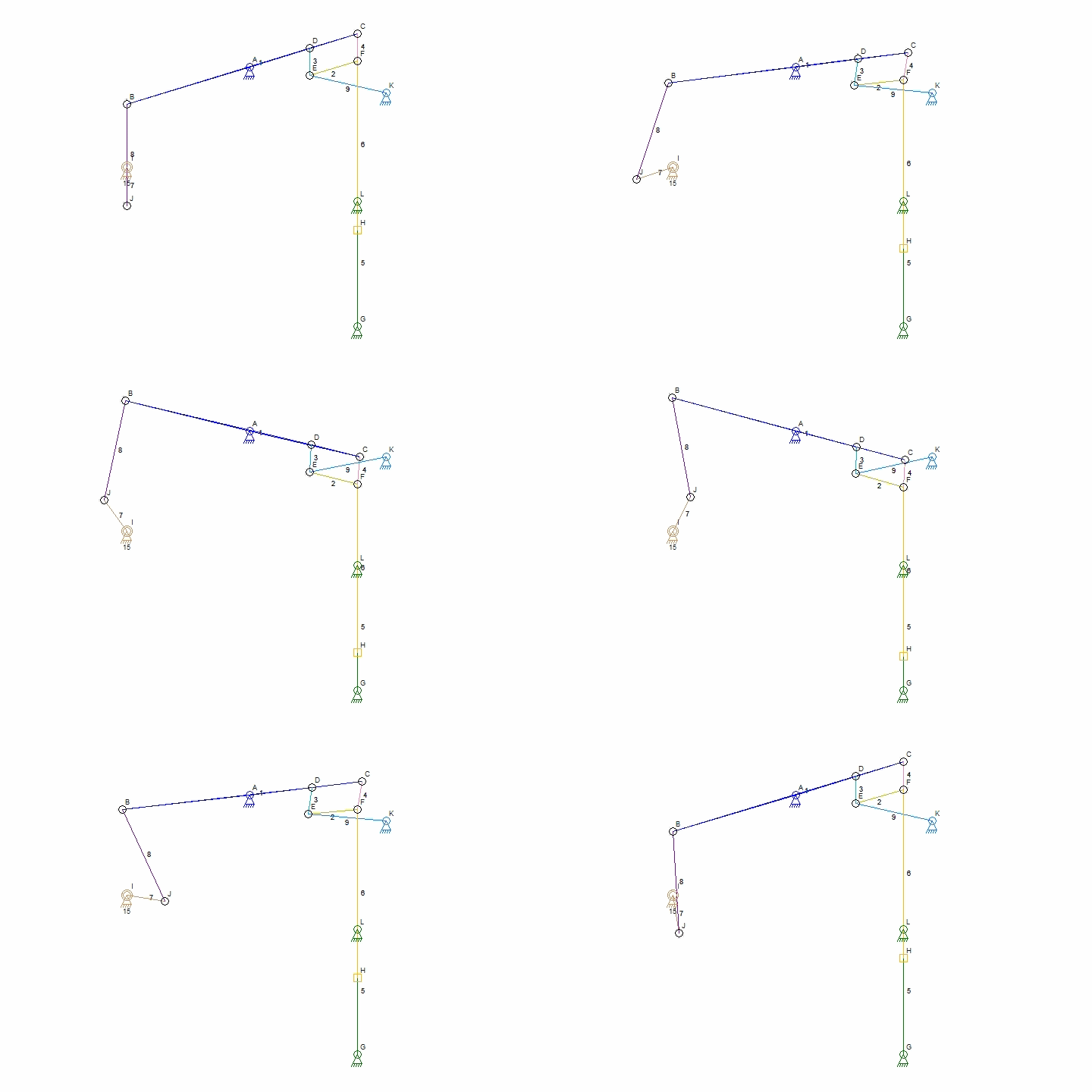

Hi Steve,

This engine definitely will have the parallel motion linkage (watts type), I just have not gotten that far yet. One end of the linkage will attach at the bearing that is part way up the main beam, another part will attach at the clevis on the piston rod/connecting-rod joint - that one will get a longer bolt to hold the extra links. Without the parallel linkage, it is possible to hand-move the engine through a cycle, but it does bind a bit at the ends of the throw.

Here is the diagram of watts linkage that I am going by (borrowed from wikipedia):
Watt_Parallel_Motion_Simulation.gif
 
Time to make the bearings to connect the crank rods to the cranks - once that is done the engine can at least be turned round by hand (and stared at for a bit!).

The bearing assemblies are in two parts - an inner brass bushing and an outer steel case (got to be a proper technical term for these parts - will google that later!).

Here is the sketch of the parts I worked out:
scan_080.jpg

I made the parts from the inside out, started with the brass core figuring it would be easier to fit the steel to that (it was). Started with a 1/2" square of brass, 3/8" long, and cut it in half. Mounted the halves together in the 4-jaw chuck, and drilled the center 1/4" and reamed it to .251. Then turned a boss on the end where it will ride against the crank web:
IMG_3748s.jpg

Turned it around (carefully lining up the halves) and turned a matching boss on the other side. Here is how it looks so far:
IMG_3750s.jpg

Then needed to cut in the slots all around the perimeter where it will slide into the steel surround - these slots are 0.050 deep, and 1/4" wide to match the steel:
IMG_3752a.jpg

Here is one with the slots around the edge, one to go. The black marks are felt-tip pen, so I could keep the two sets together and right-way-round easier:
IMG_3753a.jpg

Got out the steel bar I used to make the crank webs, and hacksawed out the rough shape for the bearing holders:
IMG_3756a.jpg

Milled the edges square and down to size, and turned the top round. Drilled/tapped the top 3/16-40 to take the connecting rod end:
IMG_3762a.jpg

Clamped the two halves together and drilled for the 4-40 bolts that will hold it all together. The top half was clearance drilled, the bottom half tapped:
IMG_3763a.jpg

Here it is so far, with the center holes sketched in. As you can see, the joint between the two halves is above the level of the joint in the brass bushing - I wanted to have the slot in the bottom half hold the two brass pieces in the proper place by itself, and not let the play in the bolts allow it to shift:
IMG_3765a.jpg

Milling out the suqare hole in the center of the steel pieces. I did the bottom pieces first, then marked the locations of the edges on the top halves to make sure they lined up when assembled:
IMG_3767a.jpg

Here are the parts so far - the bushings are a snug slide fit into the steel holders:
IMG_3768a.jpg

Last step on these parts was to radius the bottom edge so it would clear the baseplate at the bottom of the stroke. Did that with the part clamped to the rotary table with a spacer to hold it above the table:
IMG_3772a.jpg

Then, assembled the parts in the crank, so I could mark the lower ends of the connecting rods to the right length.
IMG_3774a.jpg

Cut off the excess on the rods, and turned them down/threaded 3/16-40 for the bottom 1/4". Got lucky on the first one - the shoulders bottomed out just right to line up the bearings and the clevis at the top. On the second one had to take off another couple thou. to get them lined up:
IMG_3778a.jpg

And here it all is so far - at this point can turn it over by hand. I like this stage, everything new going on actually does something. Next stage will be to make the links for the parallel motion mechanism above the pistons. Till that is done, I have not drilled the mounting holes for the cylinder baseplates - I have not done a parallel motion set before, and dont want to lock myself in on the positions until I can verify things line up properly.

Not sure if I will turn down the links from wider bar, or piece them up - have to do a little scrounging in the metal piles and a little experimenting....
IMG_3780a.jpg
 

Latest posts

Back
Top