Cutting my first Miter gear

Home Model Engine Machinist Forum

Help Support Home Model Engine Machinist Forum:

This site may earn a commission from merchant affiliate links, including eBay, Amazon, and others.

Brian Rupnow

Design Engineer
Project of the Month Winner
Joined
May 23, 2008
Messages
15,259
Reaction score
8,544
Location
Barrie, Ontario, Canada
I would like to try my hand at cutting a pair of 45 degree miter gears, similar to the ones that Swifty cut in his excellent "Article" on cutting miter gears. My cutters, (I have the full set) are 24DP and 14.5 degree pressure angle. I have some round brass stock with a maximum 1" diameter. What I HOPE to do is cut a pair of 45 degree miter gears from this 1" stock. I have Ivan Laws book "Gears and Gear Cutting" and---Holy Crap, there's a lot involved in the calculations to cut the blank, even before you start trying to cut the teeth. I am going to fumble away at this, just to see if I can actually do it or not. This is not meant in any way to upstage Swifty's thread under "Articles" on this forum. This is just a record of how I bumble through it. Don't try to follow me and build a set yourself, based on what I am doing, because I may totally screw this up. First part of the trick will be to use all of the calculations to determine the dimensions of the blank gear form.
 
Last edited:
Good luck Brian. Seems like many of us are on the same path, but at different mile markers. Once I got some reasonable spur gears I thought I'd like to make some bevel or miter gears. That's in the future though so I hope to learn from this thread.

Cheers,
Phil
 
According to Ivan Laws book, the overall gear dimension will be a resultant, based on whatever number of teeth you decide to use plus some relatively wicked geometry/trigonometry. I'm going to cheat a bit and model it in Solidworks, where by putting in the pitch circle of the small end (which will be the same as the pitch circle diameter of an equivalent toothed spur gear) and an angle of 45 degrees, the computer will calculate some of the unknowns. I COULD do it with trig, but since I have the software I will use it. I am going to guess, to get started, and use a gear with 18 teeth.
 
Last edited:
That's the best way to go Brian, I drew mine in CAD by putting in the PCD and then adding the addendum and dedendum, this gave me where the teeth should be, I just drew the rest around this. I searched a lot of information from gear suppliers regarding sizes for their gears, but this did not work out well. I think the main difference with purchased gears is that they are cut by a different method, making the blank sizes different.

The biggest tip that I can give you is to use a marking pen to show where the first tooth cut is, it gets confusing when you come to do the follow up 1/4 turn cuts as you have to move the mill table up or down and then cut on the correct side of the tooth.

I'm looking forward to following this thread.

Paul.
 
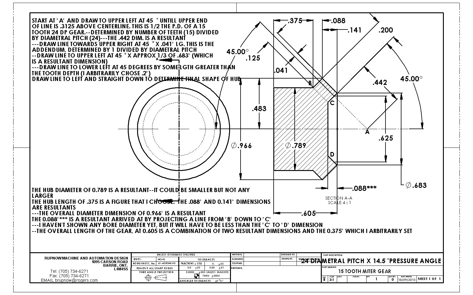
Some calculations showed that an 18 tooth gear was going to end up being a greater overall diameter than the 1" stock I have to work with. I messed around with the numbers until I found that a 15 tooth 24dp gear would result in an overall diameter of less than 1" so that's what I used. This is the drawing of the blank I arrived at, with a description of how I came up with the dimensions.


View attachment 15 TOOTH MITER GEAR.PDF
 
Last edited:
Did a quick calculation Brian and I think that your bar stock is too small. With the information that you gave us in the previous posts the PCD on the small end will be 0.75", your 1" bar stock will not be big enough.

NOTE. Our posts were done at the same time, I see that you have found this out.

Paul.
 
Last edited:
Swifty--My old mother used to say "Great minds think alike, and fools never differ!!"--I hope you and I are in the "Great minds" category---
 
The drawing looks great Brian, does that mean that we will have gears before you go to bed tonight? :p

Paul.
 
I think that in practice the undercut at the front of the gears is unnecessary, although I did include it in mine.

Just had another thought Brian, because you are cutting 15 teeth just make sure that you choose a dividing plate that allows you to shift 1/4 of a turn.

Paul.
 
Last edited:
In Ivan Laws book, where he calculates the number of teeth on the back cone, he gives the formula 1/sin45 x 20=28.8 and then establishes that he will use a 28 tooth gear so will use a cutter appropriate for that number of teeth. He is making his calculations based on a 20DP gear with 20 teeth, and I don't know which 20 the one in his formula refers to. I am using a 15 tooth gear with a 24DP so which number should I be using in that formula?--The 15 for number of gear teeth, or the 24 for DP?
 
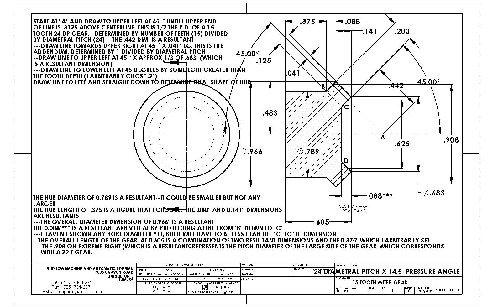
Okay--based on a direct measurement of my layout, the pitch diameter at the rear side of the cone looks like 0.908, which multiplied by the DP of 24 =21.8, so round it off to 22 teeth.
If I use Ivan Laws formulae and use the number of gear teeth at the small diameter of the come (which is 15t) then the formula gives 1/sin45 x 15=21.2 so I assume it must be the number of teeth on the small side of the cone that gets used in the formula.
My gear cutting charts show that for a 22 tooth gear you use a #5 cutter which cuts from 21 to 25 teeth. It is the calculated number of 22 teeth that determines which gear cutter you use, even though the gear will ultimately only have 15 teeth.


View attachment 15 TOOTH MITER GEAR.PDF
 
Last edited:
Now comes the trick part---The divider plates. My rotary table has a 90:1 ratio. My charts say that to cut a 15 tooth 24 DP gear, I can use any divider plate. 360 degrees divided by 15 teeth =24 degrees between teeth. 360 divided by 90=4 degrees rotation for each full turn of the crank on my rotary tables handle. 24 degrees divided by 4 degrees=6 full turns of the crank on my rotary table. This is fine for the initial cuts, (I think) but then I have to rotate the gear by a number of degrees equal to 1/4 of the tooth indexing angle, to do the next series of cuts. If there are 24 degrees between teeth, then 1/4 of that is 6 degrees rotation of the table. To get 6 degrees rotation of the table, I have to turn the crank on my table 1.5 full turns. I have a 20 hole divider plate. Now one full turn of the crank on a 20 hole divider plate will move the table thru 4 degrees. So--if I turn the handle thru 1 1/2 turns that gives me 1.5 x 4=6 degrees, which is 1/4 of the table rotation between gear teeth. That should mean that by turning the the crank thru one complete revolution and then advancing it another 10 holes when using a 20 hole divider plate, that I have advanced the rotary table 1/4 of the angular distance between gear teeth.
 
Last edited:
I'm trying to get my head around this Brian, but I don't have a rotary table, only a dividing head. Maybe they work different, I don't know.
If they work the same, the 360 degrees divided by 90 ratio of the table = 4 degrees per rotation of the crank, as you said. So 6 full turns of the crank = 6 x 4 degrees = 24 degrees. You then need 6 degrees rotation, which equals 1.5 turns of the crank, again, as you said. Then, and this is where I get hazy, you say 1 turn of the crank now changes to 90 degrees if you use a 20 hole plate. If I disregard this statement, and use my working knowledge of a dividing head instead, you now need to go 30 holes on your 20 hole plate to equal the required 6 degrees (1.5 turns).
I figure there must be a difference between the tools that I'm not aware of, although the info I've been googling doesn't show me what the difference is.
Feel free to let me know where I stuffed up!
 
I have just returned from having my spine pulled out thru my buttocks by the physiotherapist, and I think I have come up with the right answer to my gear question. Please have a look at post #13 and see if I have it right this time.---Brian
 
Last edited:
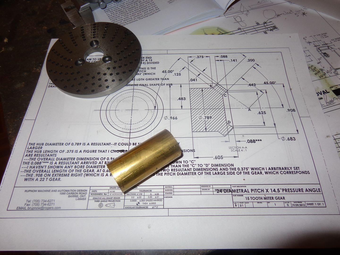
This is what may (With the grace of God) become two miter gears. Its a round piece of brass, 1" dia. x 2" long. Since I need something to hold onto with the 3 jaw chuck on my rotary table, I am going to cut a miter gear on each end of it and then split it in half.--Hopefully!!! In the background is the 20 hole divider plate.
 
Last edited:
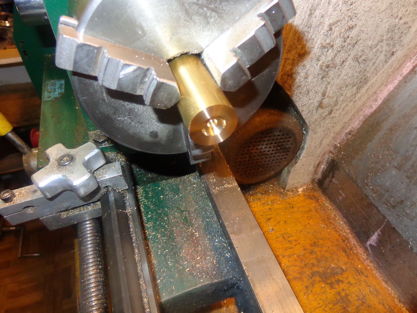
Here we are with a 0.5" diameter x 0.088" deep counterbore in each end. I used a center drill in each end first because my 1/2" endmill is a 4 flute and doesn't cut right at the center.
 
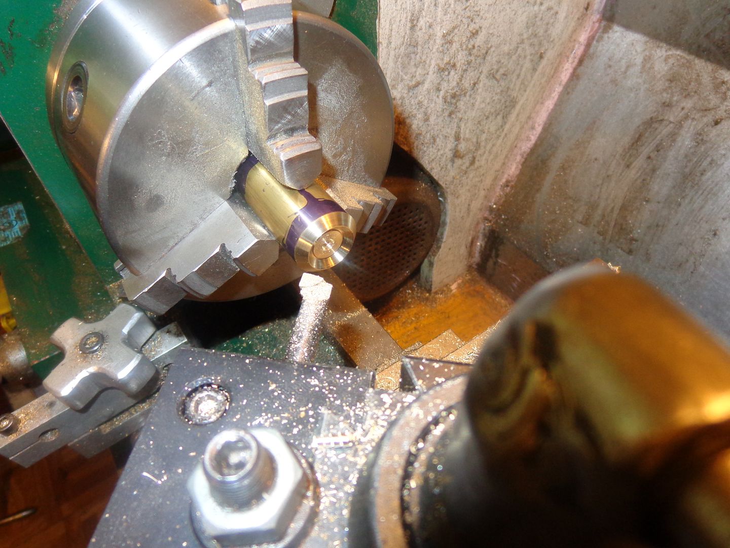
Both ends are turned to a 45 degree angle, 0.141 back from the end as per the drawing. This newly exposed surface is what will actually become the "tip" of the gears after they are cut. The next step is to set things up in the rotary table. Even though there is an area of reduced diameter immediately behind the tip of the teeth, I don't have to put that in yet. If I did, it would be too difficult to hold properly in the 3 jaw chuck on the rotary table. It can be put in later.
 
Last edited:
Okay--I lied!!! There was one more lathe operation before I head over to the rotary table. I cut the internal 45 degree surface that runs from the front of what will become the teeth in to the .5" diameter which I put in during my first step. This wasn't a perfect match, so I put the end mill back in and cut just a tiny bit deeper until everything ran out properly with no obvious ridges left at the junction.
 
Last edited:
And just in case nobody thought about it--If this works the way I hope it will, these are the miter gears you need to run the governors on the Rupnow Engine.
 

Latest posts

Back
Top