Cutting my first Miter gear

Home Model Engine Machinist Forum

Help Support Home Model Engine Machinist Forum:

This site may earn a commission from merchant affiliate links, including eBay, Amazon, and others.
Hi Brian, I'm just having my breakfast down here and reading all your latest posts. Now you know why I had to read Ivan Laws book about 4 times before I started to get my head around everything, and then I had to work with the module gear system.

You seem to have everything worked out correctly, now you can see why my earlier comment on choosing the correct dividing plate is important, an odd hole pattern will not allow you to get the 1 1/2 turn, even though it would have been OK for the main cuts.

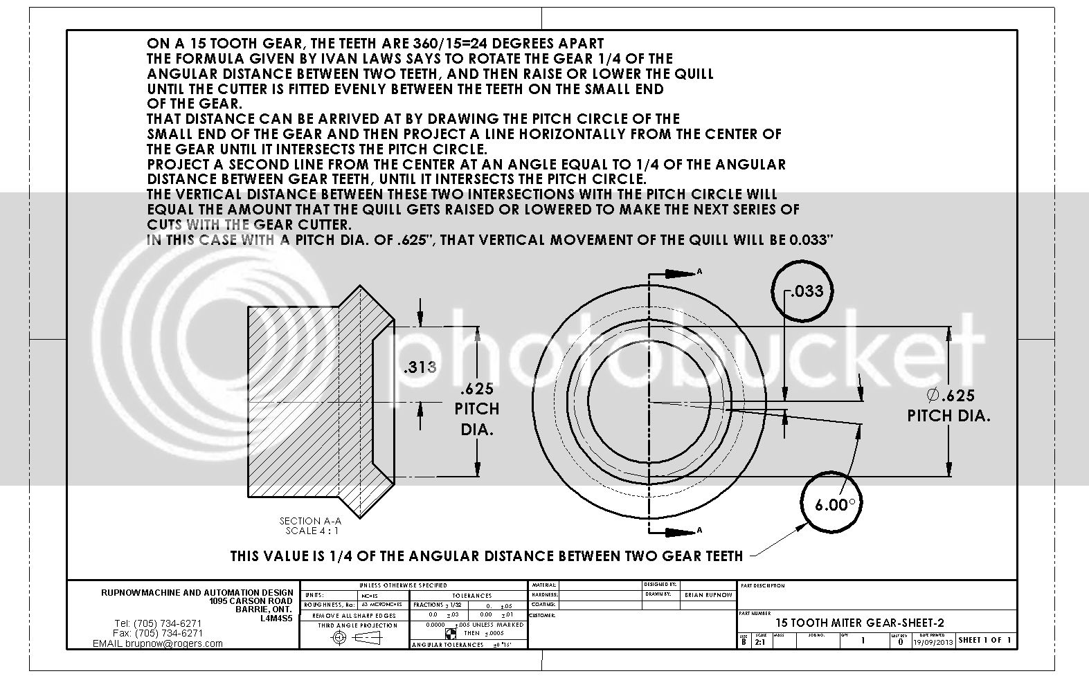
You are now well on your way to cutting the gears, the only hard part left is when you do your second and third cuts, make sure that you cut on the correct side of the tooth. Ivan Law had a formula for working out the table rise and fall, I gave up at this stage and just adjusted the table so the cutter entered the small end of the gap precisely.

Paul.
 
And don't forget, after advancing the gear 1/4 of a turn and making all the cuts, you then have to back track that 1/4 of a turn to get back to the initial setting and then turn back 1/4 of a turn for the other cuts.

I suggest that you take the phone off the hook, lock yourself in and don't have the radio on as any distraction at this stage will get you confused.:confused:

Paul.
 
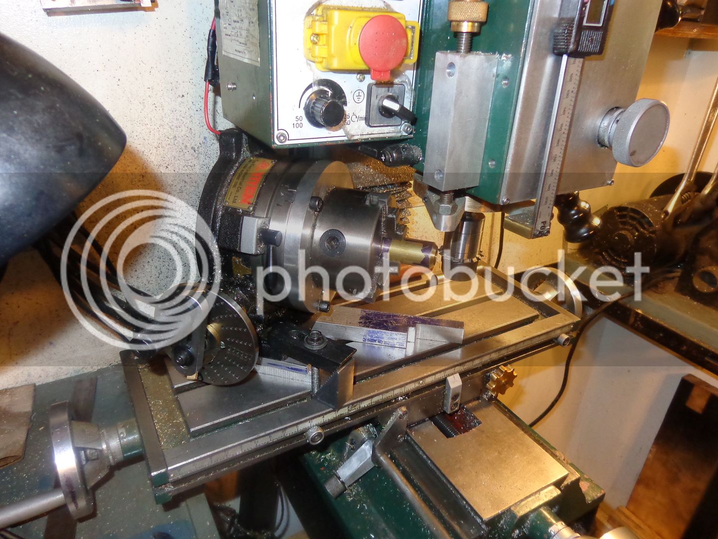
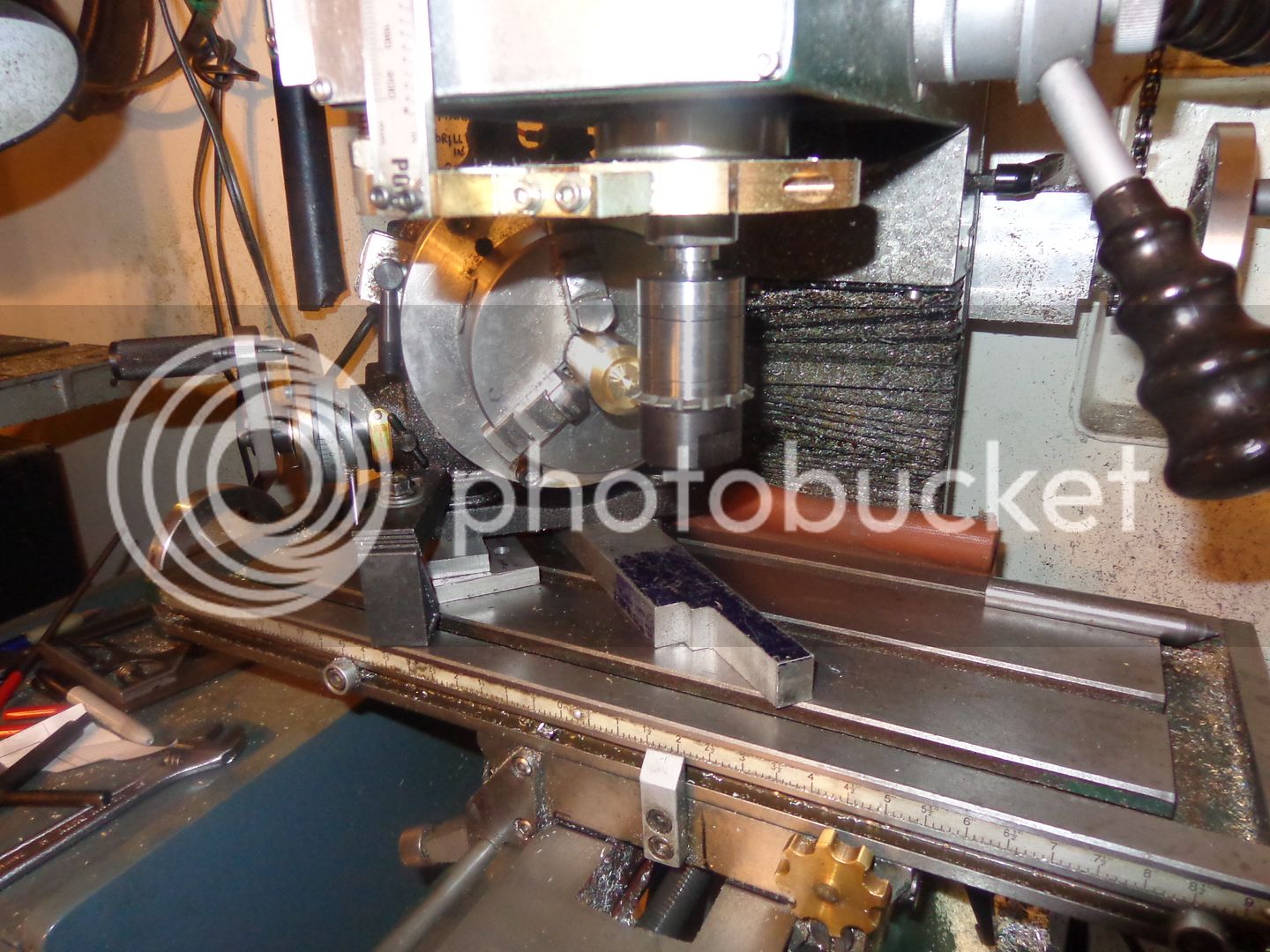
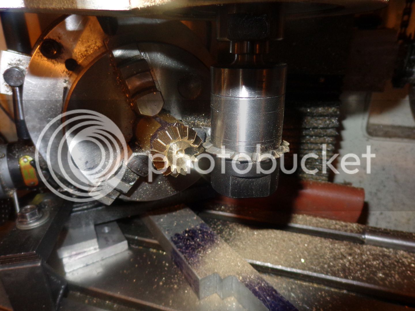
So---Here is my set-up, which at best I can only call "Buck-Shee". After getting everything set up the first time, I discovered that my "Made in India" divider plates were so large in diameter that they wouldn't fit on the spigot of the rotary table without hitting the mill table, so I had to put some 3/4" aluminum spacers under my rotary table and start over again, so that the divider plates and handle would fit in place. My mill doesn't have a particularly deep throat, so the back end of my rotary table is within a gnats ass of crushing the vertical bellows that covers the front of my column. However, I am set up, the rotary table is set at 45 degrees, (or as close as can make it). The centerline of the cutter is on the centerline of the 3 jaw on my rotary table, and I'm about to cut loose. I will cut the first set of teeth tonight after dinner, and wait until tomorrow morning (after good wife has gone to work) to start any of the tricky/funny business.

 
Last edited:
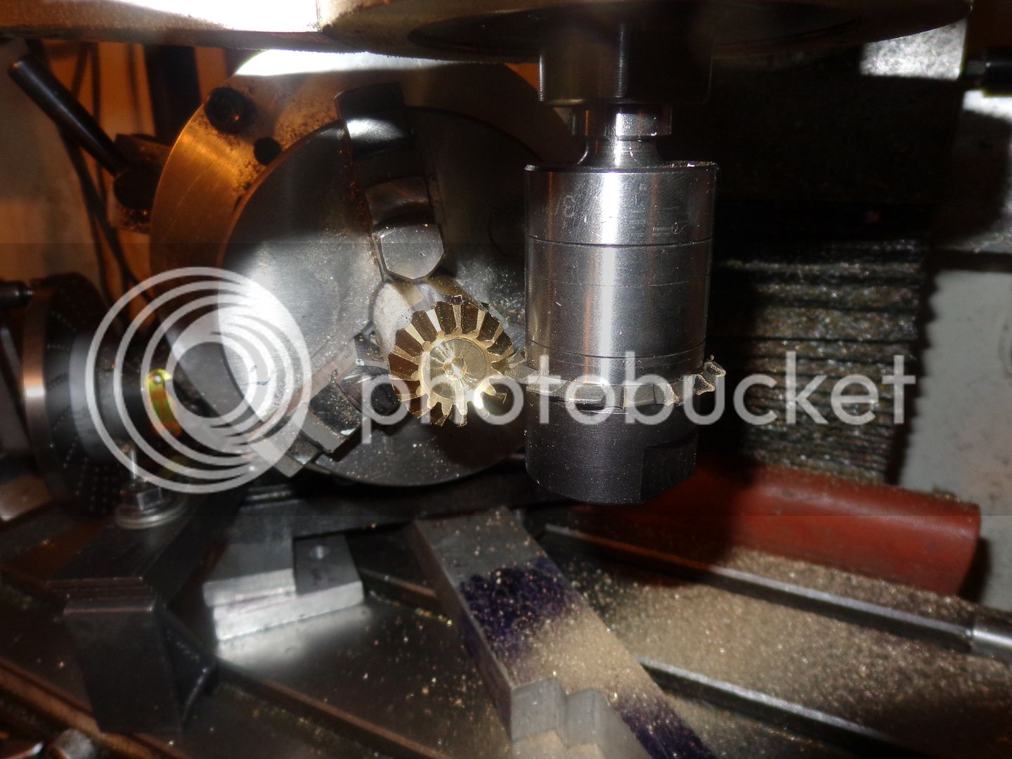
That seemed to go well!!! At least when I got all the way around I was cutting air, not a half tooth. It looks a bit weird, but should get better with more steps.

 
Last edited:
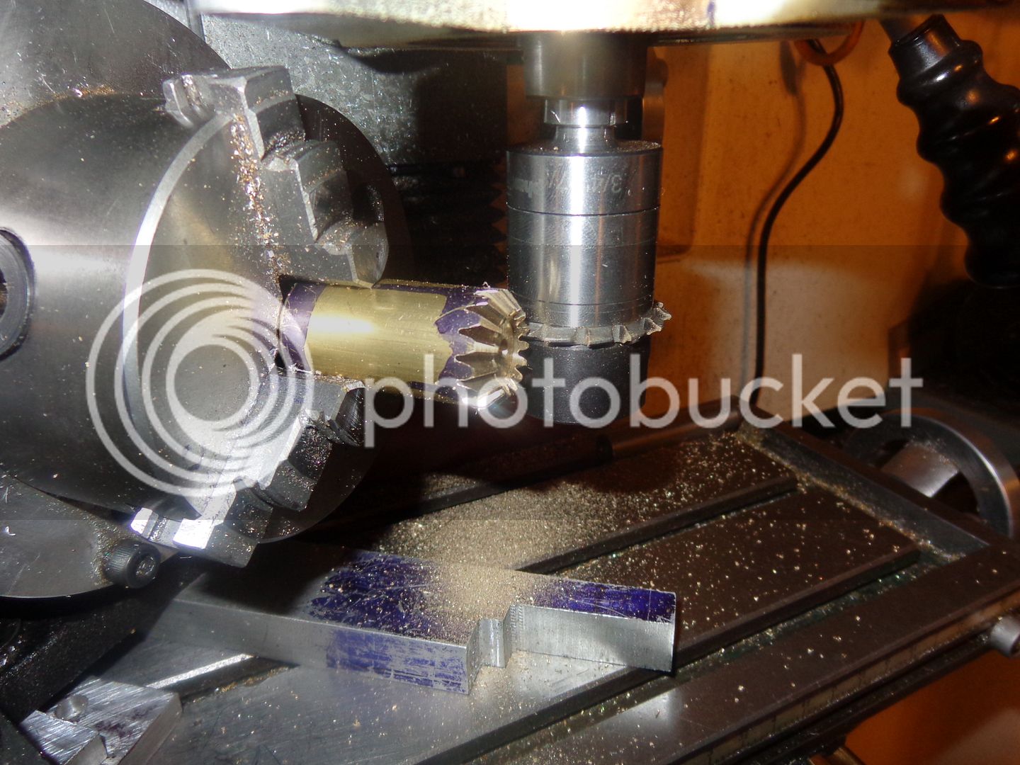
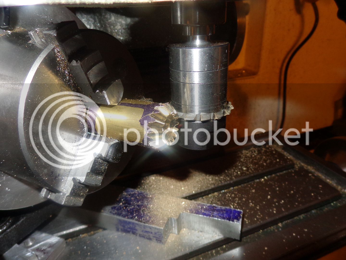
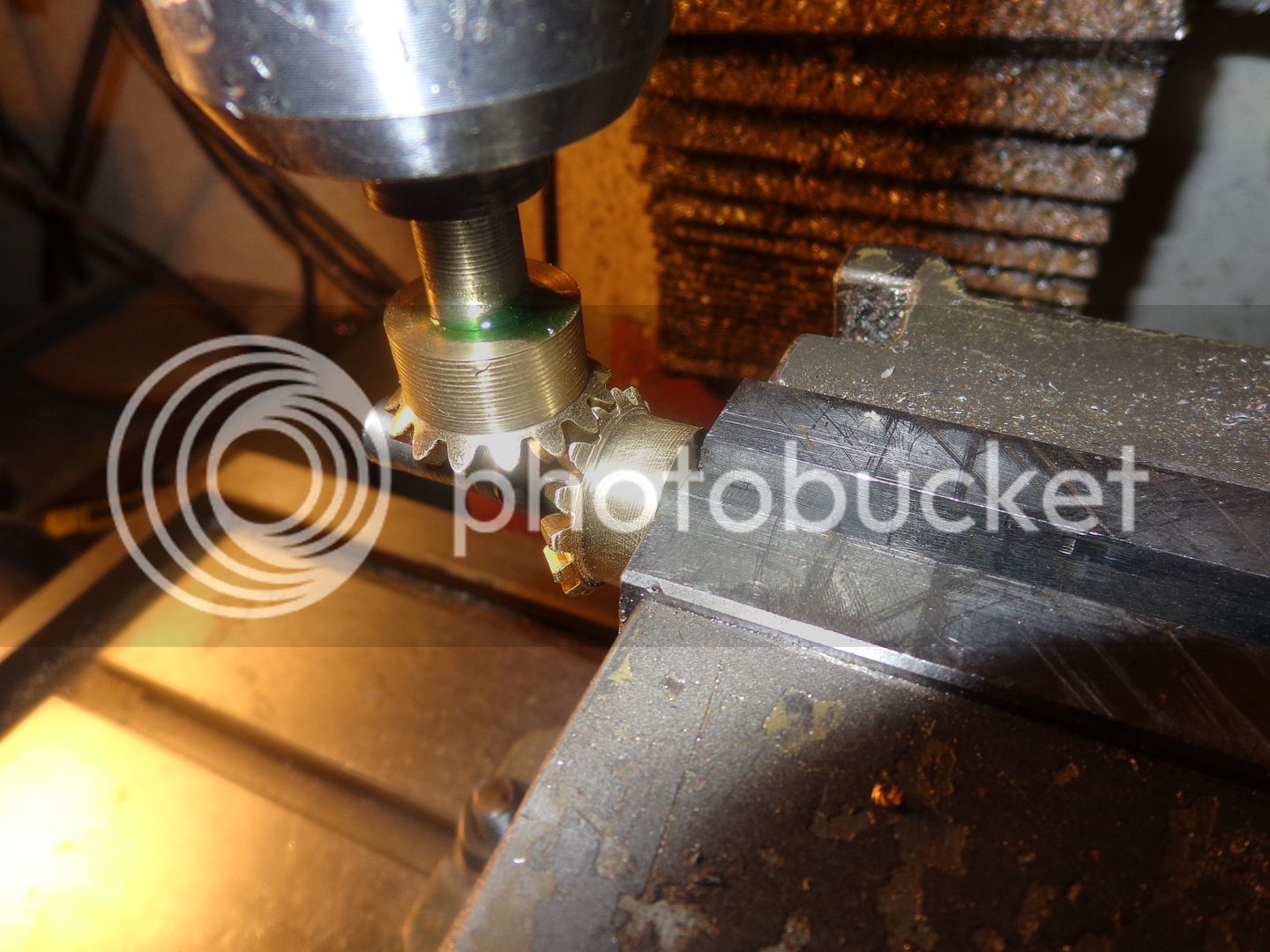
This was just too exciting to wait until tomorrow to make my final cuts. I made the second cut all the way around on all teeth, and then the third cut all the way around on all of the teeth. This necessitated raising and lowering the quill by a calculated amount, and I figured out how to make that calculation--its quite easy. --And by God, it does look good. The teeth are parallel on each side of the crest, but the gaps at the root of the teeth are at an angle, just like they are intended to be. Of course, the proof of the pudding will be seen when I cut the teeth on the other end and split the brass round into two separate gears and mount them in a pair of 90 degree bushings to see how they mesh!!!

 
Last edited:
Brian, I'm just a bit nervous, you mentioned that you had parallel teeth and a tapered gap. I don't want to be negative, but I believe that you need tapered teeth and tapered gap so they mesh correctly. I had parallel teeth on one of my trial gears but it was not correct, I can't recall how I got straight teeth. The proof will be if the two gears mesh both top and bottom.

Paul.
 
I'm still thinking about things, at the large end of the gear, the tooth size at the pitch circle should match the gap size at the pitch circle. Then the teeth will mesh correctly. I see that you marked where the first cut was made, it's important when doing the second and third cuts that you have this first gap bought back to centreline and then offset 1/4 of a tooth in the direction you want. The next cuts must enter the same marked gap first off. I think I entered the wrong gap, and that's why I had straight teeth on one trial gear.

In Ivan Law's book, you will see that the sides of the teeth are all radial to the centre, and this will automatically give tapered teeth.

In my article on cutting the mitre (miter for our American friends) gears, you can see that the teeth are definately tapered in the photo.

Paul.
 
Last edited:
Hi Brian,

I did goof around with cutting my own bevel gears some time ago as well. I found a book by Ernst Wiedmer in my universitys library. It is written in german and metric only, but the formulas are quite simmilar to the ones in Ivan Law´s book. except for he calculates the number of teeth for selecting the cutter by dividing the number of teeht of the bevelgear by the cosine of the angel. but in your case this doesn´t make any difference since it is 45 degrees ;-)
I would like to post these formulas, but I dont know if I´m allowed to.


Well, I ended up with tapered teeth and tapered gaps just like Swifty.

Maybe you didn´t move your blank and cutter in the opposite directions when doing the second and third cut?
 
Another thought, if you moved 1/2 a tooth this would bring the tooth on to centreline, follow up cuts either side of the tooth would make a straight tooth form as well.

Sorry, I think that you might wake up to some bad news.

Paul.
 
hmm,

I´ve been thinking about my last comment for quite some hours, but I couldnt understand why the blank and cutter should be moved in opposite directions. that way you would be cutting away the entire tooth..:confused:

I figured out I missinterpreted the image given with the formulas :mad:

blank and cutter actually have to move in the same direction.. :wall:
Sorry for that missinformation
 
hello,

I had a look at the your pictures again, especially the last one.
I noticed that the scratchmarks of your gearcutter are not parallel to the top of the tooth.
Seems like you got the wrong angle in either your rotary table ore your lathe compound. therefore the cuter took a deeper cut at the end of the tooth making its sides look like they were parallel..

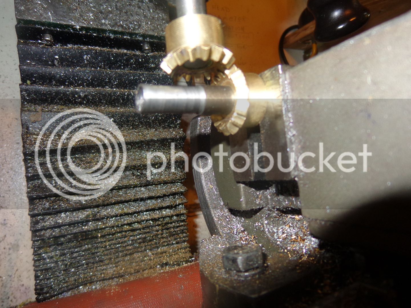
In the second last picture you can see (especially at the teeth around the 4 o´clock position) that thei get more "pointed" towards the end. They should be the same hight throughout.
 
Last edited:
I THINK I got this right. Its hard to get a good picture of. Perhaps the edges of the very crest of the tooth are close to parallel, but the actual tooth cross section gets larger and larger as it moves from the center towards the outside of the blank. as far as I know, that is what I wanted to achieve.
 
Last edited:
  • Like
Reactions: gus
Hi Brian and Paul,

Gus is having cold feet cutting mitre gears. Will cheat. No calculations. Copycat from "KG Gear,Japan Cataloque.
The good reason or bad excuse is I have Module 0.8 and 1.0 Metric Gear Cutters.
Paul will be reading your article on cutting these mitre gears.
Carb done except for the soldering and needle. its weekend fishing again.
 
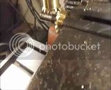
Ahhh---Sweet Success!!! The gears seen to mesh perfectly. This isn't something I would rush to do again, but I'm surprised at how easy it actually is. I don't really need them for anything---I just wanted to see if I could do it. If any of you have been considering cutting your own miter gears, then rush out and buy a copy of "Gears and Gearcutting" by Ivan Laws, read thru my thread, and have a look at the excellent article Swifty did in the "Articles" section of this forum.--The top picture is actually a video and the bottom two are just pictures-Brian


Last edited:
Congratulations Brian, nice work. Thanks for posting

Cheers,
Phil
 
Congratulations Brian, I'm so happy for you. When you mentioned earlier that the teeth were parallel, I got very worried. I hope I didn't upset you with my concern.:)

Paul.
 
Gus, you cannot use the dimensions that appear in gear catalogues, they use a different method of cutting and the blanks would be too small for you to use. They all seem to use the PCD at the large end of the gear, whereas we use it at the small end.

If you need blank sizes, let me know the module and number of teeth and I will send you a blank drawing.

Paul.
 
Swifty--If you hadn't posted your "how to" in the "articles" section, I would never have been brave enough to try this.
 

Latest posts

Back
Top