
;D ;D
Hi Guys,
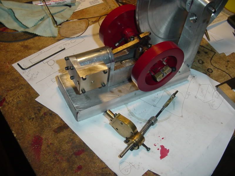
Ain't valve gear fun :big: :big: :big: :big: :-\ :-\ ;D ;D ;D
Brian,
Don’t get me wrong my friend; I am not saying your design will not work.
In fact I expect it to work just fine, just like all your other engines, since the valve over travel is, in this case, not going to present any major issues.
What I was trying to establish was how you came up with the eccentric offset and your explanation provided the answer. No problem on that score and in this particular case it should not give you any issues.
Ok, having established your method, what I am now trying to convey to you (and any others who may be following this thread) is that the required valve travel, and hence the eccentric throw are not directly related to the crank throw but to the required cylinder port width, which in turn is related to piston speed, piston area and steam velocity.
Piston speed is directly related to rpm and the engine stroke, so in this instance crank throw is important… but not in the way you are relating it.
Lets take a couple of examples: -
1st lets take an engine with 1” bore and 1” stroke rotating at 500 RPM
2nd Lets compare this to an engine of 1” bore but having a 5” stroke rotating at 100rpm.
If you use the formulae I gave you in my last post, and using 4000 for the steam velocity, you will see that in both these cases the required port cross section area is identical at 0.01635 sq ins.
edit: in the previous posted formulae I neglected to state that the resulting cross sectional area (a) is in sq.inches. Original post edited to add this fact. end edit.
The piston speed is also the same in both cases (83.333ft/min) but the strokes are not; with the second example being 5 times greater.
In both cases the required port cross section can be obtained by drilling a hole of 3.7mm dia (0.145”

, this being the nearest generally available drill size (actually a number 27 drill).
The required piston valve would need to have a land the same as the port width (0.145”

and the total travel required would be twice this value (0.290”

in order to open the port fully to both steam and exhaust.
From this it is clear that the eccentric throw is only required to be the same as the port width at 0.145”.
Clearly the same valve and eccentric dimensions can be applied to either of the example engines and both would work to the design specifications.
Ok, lets compare this to the values you would get using your method for these 2 examples: -
In example 1 the stroke is 1” so the crank throw is 0.5”.
If you now deduct half of this we arrive at 0.25”.
If we also deduct the port width (0.145”

we arrive at 0.105”; which is smaller than the port width.
You then go on to further deduct ½ the port width (0.0725”

; which results in 0.0325” for the eccentric offset.
The result would be an eccentric having a total throw of only 0.065”.
Clearly this is not correct since it results in an eccentric with far to small a throw.
In the second example we have a stroke of 5” so the crank throw is 2.5”
Deducting ½ of this we arrive at 1.25”.
If we now deduct the same 1½ x port width from this (0.145" x 1.5 = 0.2175”

we arrive at an eccentric offset of 1.0325”, which will result in a total throw of 2.065”
Again this is clearly not correct since we now have an eccentric with an extremely large throw.
Ok Brian, please do not think for one minute that I am picking holes in your design… nothing could be further from the truth.
What I am trying to do is help you to understand the theory a little better, I hope it will be seen as such.
This whole issue becomes far more important when you come to designing double acting engines where the valve travel must be constrained to quite tight tolerances…or very strange things, or even damage, can occur.
To this end, I trust the above will go some way to your understanding and help you to design your engines more easily.
Best possible regards.
Sandy. ;D ;D


![DreamPlan Home Design and Landscaping Software Free for Windows [PC Download]](https://m.media-amazon.com/images/I/51kvZH2dVLL._SL500_.jpg)


![TurboCAD 2020 Designer [PC Download]](https://m.media-amazon.com/images/I/51UKfAHH1LL._SL500_.jpg)


![MeshMagic 3D Free 3D Modeling Software [Download]](https://m.media-amazon.com/images/I/B1U+p8ewjGS._SL500_.png)


