Chucks Single--Conventional Valving

Home Model Engine Machinist Forum

Help Support Home Model Engine Machinist Forum:

This site may earn a commission from merchant affiliate links, including eBay, Amazon, and others.

Brian Rupnow

Design Engineer
Project of the Month Winner
Joined
May 23, 2008
Messages
15,249
Reaction score
8,525
Location
Barrie, Ontario, Canada
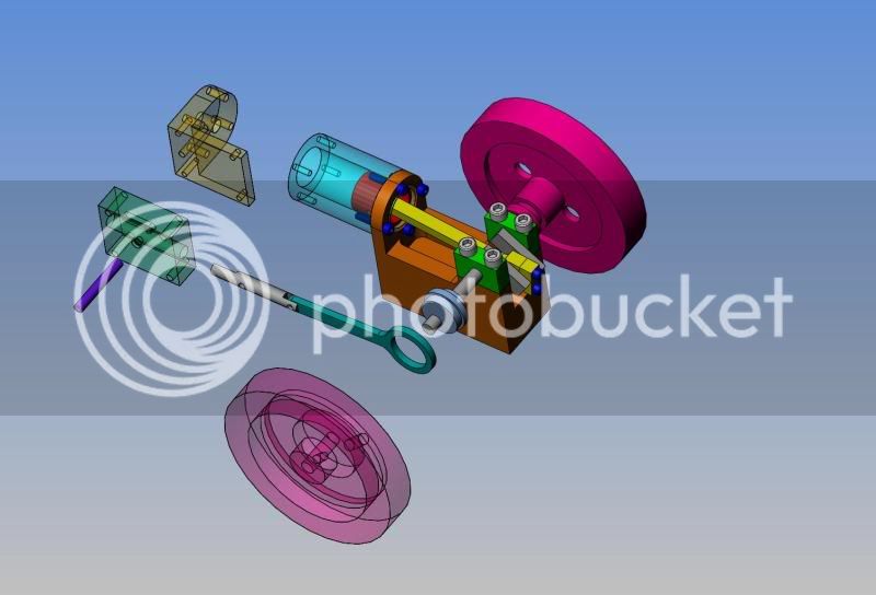
Just to prove that I'm going completely gaga with LOWS (Lack of work syndrome) I decided to see what was involved in a redesign of the Chucks Horizontal engine that I built, to put conventional valving in it. This managed to burn up most of yesterday, and did give me insight into valve timing and design that I didn't have before.
FULLASSYHITANDMISSENGINE-4.jpg
 
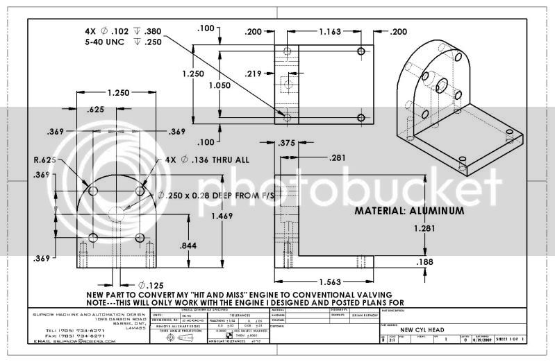
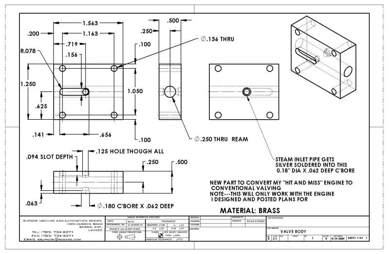
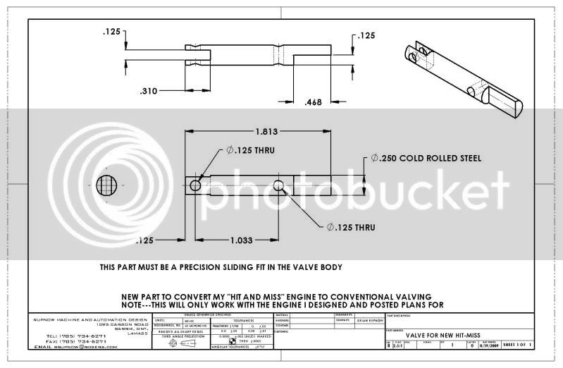
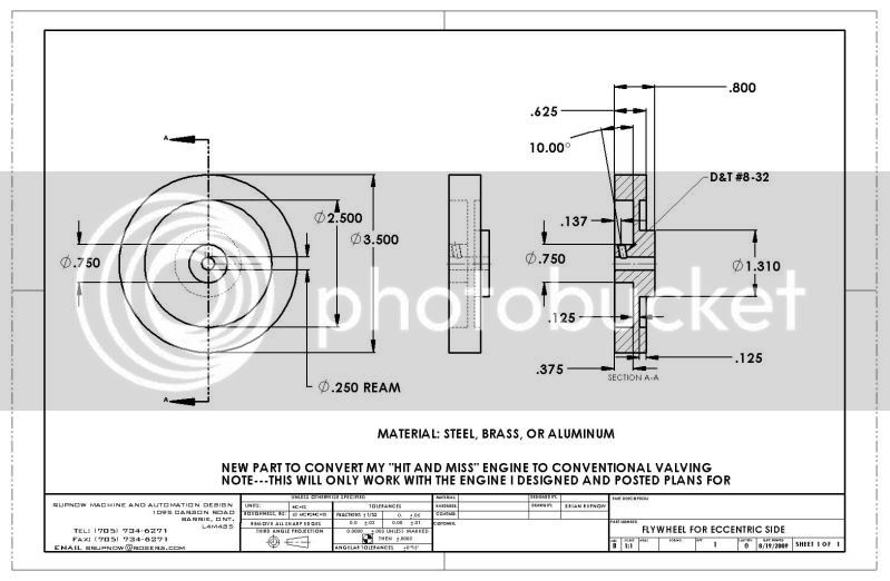
I'm not actually sure that I will do this. I like my engine just as it is, with the current valving on it and the hit and miss governors. This was more of an intellectual exercise to better aquaint myself with the design of small steam engine valving, and to see what would actually be required to make this change. If anybody out there in steam engine land wants to make this change I will post detail drawings of the parts so you can machine them.---Brian
 
Nicely done Brian. :bow: Wish I could produce CAD drawings such as those but do not have the software or the training to do so. It would make life so much easier to do things that way, I think. Now, for your next assignment, redesign the head utilizing poppet valves. ;D ;D

Regards

BC1
Jim
 
Thm: Nice, straight forward, and simple to build. I think just from a fabrication stand point, since I only have a milling attachment for the lathe, I would break the head / valve assembly into 3 parts. Valve front and back and head. I think it would cut down on some milling. I have always liked that type of valve for its simplicity.

I am looking at several plans for this type of engine for my next project. I have not decided to stay with a set of plans or incorporate parts of each that I like. I usually vary from the plans anyway to make use of materials I already have on hand. By far this is the simplest way to go for the valve.

Go ahead and post the drawings and I will have a go at incorporating it into my project.


Brian, Thanks for posting them.

Any particular reason the eccentric strap and flywheel are in .jpg format instead of .pdf like the rest of the files? Just wondering. scratch.gif scratch.gif scratch.gif


Ron
 
ozzie46 said:
Brian, Thanks for posting them.

Any particular reason the eccentric strap and flywheel are in .jpg format instead of .pdf like the rest of the files? Just wondering. scratch.gif scratch.gif scratch.gif


Ron

Ozzie--I hadn't noticed that. I fixed it.---Brian
 
Brian, I just wanted to tell you how much I enjoy your post's I have read most all of them and really enjoy how you design and build your engines if I might make a suggestion why don't you design and build a multi cylinder engine one that really makes you use your brain Cliff.
 
Cliff said:
Brian, I just wanted to tell you how much I enjoy your post's I have read most all of them and really enjoy how you design and build your engines if I might make a suggestion why don't you design and build a multi cylinder engine one that really makes you use your brain Cliff.

Cliff---I'll take that as a kind of left handed compliment. My poor old brain is stretched right to the limit messing about with these one and two cylinder engines. You have to remember, that up untill 2 years ago, I really had no experience running a lathe or a mill. Truly, I get as big a thrill out of a simple single cylinder engine as I would out of a multi cylinder monster.---Brian
 
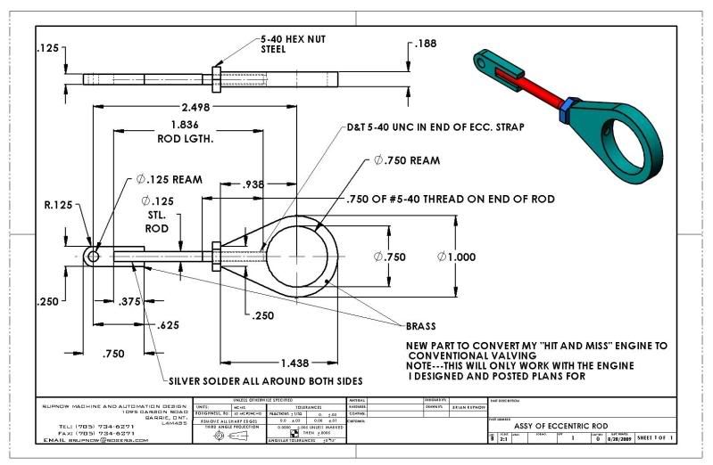
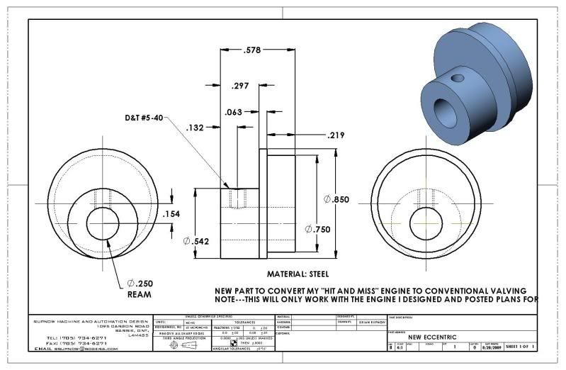
This morning I changed the plain eccentric strap to an adjustable length assembly and changed the eccentric detail a bit as well.
 
:) ;D

Hi Guy's,

Brian: - Interesting modification you have made which goes a long way to displaying the different valve operating linkages that can be used on this type of engine.

One question I have though...... why have you chosen the eccentric throw to be 0.308" when the valve only needs to travel 0.25" between full steam/air and full exhaust?

I accept that this may make setup a little less exacting, however, this just seems a large amount of lost/wasted travel and also makes the eccentric and eccentric strap larger than necessary.

Did you have a specific reason?....... Not picking holes, I'm just curious.

Next version should be DOUBLE ACTING with SLIDE VALVE or PISTON VALVE. :p :p ;D ;D

Best regards.

SandyC ;) ;) :D
 
SandyC said:
:) ;D

Hi Guy's,

Brian: - Interesting modification you have made which goes a long way to displaying the different valve operating linkages that can be used on this type of engine.

One question I have though...... why have you chosen the eccentric throw to be 0.308" when the valve only needs to travel 0.25" between full steam/air and full exhaust?

I accept that this may make setup a little less exacting, however, this just seems a large amount of lost/wasted travel and also makes the eccentric and eccentric strap larger than necessary.

Did you have a specific reason?....... Not picking holes, I'm just curious.


Next version should be DOUBLE ACTING with SLIDE VALVE or PISTON VALVE. :p :p ;D ;D

Best regards.

SandyC ;) ;) :D

Sandy--I'm still figuring this valve business out. It seems that for every possible configuration of valving, it changes. In this case, the throw on the crank is 0.62". That should mean that the throw on the eccentric is exactly half that, or 0.31. However--and this is the part that was driving me crazy--on this particular configuration it seems to be half the crank throw, minus the port diameter in the valve (which is 0.125") minus 0.031" to give a grand total of 0.154" eccentric offset. I didn't come by that calculation out of thin air. I went so far as to model an engine by Rudy Kahoupt, just to see how he handled it. After setting it up that way and doing the animations, it seems to work correctly. Its not just a matter of how far the valve has to travel to cover and uncover the ports---There is also a big consideration given to "DWELL"---How long the valve stays in a particular location. I am currently machining the peices I designed to see if what I calculated actually works.---Brian
 
Brian Rupnow said:
Cliff---I'll take that as a kind of left handed compliment. My poor old brain is stretched right to the limit messing about with these one and two cylinder engines. You have to remember, that up untill 2 years ago, I really had no experience running a lathe or a mill. Truly, I get as big a thrill out of a simple single cylinder engine as I would out of a multi cylinder monster.---Brian
Brian I understand but I still enjoy your post's especially when you are making a engine. Cliff.
 
;) ;) ;D ;D

Hi Brian,

Yes I agree valves and valve timing etc can be somewhat confusing at times.

Ok that explains your reasoning and on the face of it has resulted in at least a workable solution, however, I am not quite sure where you latched on to the idea that the eccentric throw had any direct, or indirect, relationship to the crank throw. Perhaps this came from Rudys’ writings but I am not aware of all his work.
One thing is for sure though, that idea is simply not true.

The crank throw only dictates the stroke length of the cylinder and the only possible bearing this would have on the valve gear would be in defining the correct cross sectional area required for the steam/exhaust ports for a given maximum speed of rotation. In this case the stroke length would dictate the maximum velocity of the piston. I.E. a long stroke engine rotating at the same RPM as a short stroke engine would have a much higher piston velocity and this in turn would effect the size of the required steam ports.

The actual formula for port cross sectional area is: -

a = Av/V

Where A = the area of the piston in sq ins.;
v = piston speed, in feet per minute;
V = velocity of flow of steam, in feet per minute.
a = port cross sectional area, in sq. ins.

The values of V commonly used for the steam velocity are 4000 for the EXHAUST and 6000 for the INLET, however, in the case of a slide valve or piston valve, where the same port is used for both Inlet and Exhaust the lower figure of 4000 should be used.
This will determine the required (minimum) cross sectional area for the ports.

Having calculated the required cross sectional area then the actual shape/dimensions of the ports can be determined…. In your case this is a 1/8” dia hole….. in most slide valve engines it would be a more rectangular shape and generally would have a length of between 0.6 and 0.8 x the bore of the cylinder and having a width large enough to achieve the cross sectional are required.

Once this width is determined then the required valve travel can be defined and it is THIS that dictates the THROW required from the eccentric.

To sum this up then, the eccentric throw required for a directly connected valve drive (such as you are using) is dictated solely by the valve travel required to fully open the cylinder port to either STEAM or EXHAUST, which in turn is directly related to the port width in the steam chest.
Sadly this is not the case with the more complex valve gears such as ‘Stephensons’ link etc where several other factors such as die slip and other geometric angularity losses would need to be taken into account, however, they are for another time.


The valve you are using is known as a Line on Line valve having neither LAP nor LEAD and in your case it is an INSIDE ADMISSION valve, since the steam/air is fed into the valve centre chamber.

In this type of valve the lands of the valve piston are exactly the same width as the steam ports…. In your case this is 1/8”.
With the piston at TDC the valve is positioned such that the land covers the port exactly and from this position it would only need to travel 1/8” in either direction in order to either fully open the port to steam or to full exhaust, therefore, the total travel required would be 0.25”….. It can of course be made more, however, it serves no real purpose and only results in additional wear on the valve piston and bore.

This 0.25” is the required total throw from the eccentric, so the offset (eccentric radius), as you know, would be half of this…. In this case it is 1/8” or the same as the steam port width.

The eccentric would be positioned such that the CROWN (high point) of the eccentric is at 90 degrees to the crank and trailing (lagging behind) the crank for the given direction of rotation.

I attach a PDF showing such a piston valve (albeit for a double acting engine) from which you should be able to work out the movement of the valve in relation to the piston/crank angles. Clockwise rotation is shown.

For a single acting engine (as yours) just ignore the right hand cylinder port, the right hand valve land and the inner bore shown on the valve… these are only required for double acting…. And the central groove should be a minimum width of 2 x the port width…. The remainder of the right hand side can be the full solid diameter.

Hope this is of some help, but if not, or you need some further input, then just shout.

Best regards.

SandyC ;D ;D ;) ;)


View attachment Piston Valve Inside admission with no lap or lead (line on line).pdf
 

Latest posts

Back
Top