Building Rudy's Steam Tractor

Home Model Engine Machinist Forum

Help Support Home Model Engine Machinist Forum:

This site may earn a commission from merchant affiliate links, including eBay, Amazon, and others.
Very nice Dennis.

Another thought about my tractor, I placed a double wall inside my firebox area.
This has maybe 1/8" insulation between the inside and outside wrappers. This also helped control the heat and helps keep paint on the firebox side sections.

Doug
 
Fantastic! Awesome post. Man I like your work.

I let out an audible 'augh' when you said you hadn't taken a pic of the rivets...wife thought I'd hurt myself...glad you had some more.

Neat tip on the double-sided tape...I'd never used double-sided tape in my life until a few months ago.
 
I'm with Zee. I like your work too, Dennis.
You do a darn good job of things.

Dean
 
You make it look so easy Dennis,,,just amazing work.
 
Dennis, I'm learning so much from your thread - thanks for posting all the detail. Fabulous looking tractor so far.
 
Hi Dennis, great metal fabrication on your build. It looks like you've been doing this all your life. The rivets sure add a nice finishing touch to the engine. When I built mine I didn't go to that extent but that was when I was just starting out didn't see the overall look of the engine.
George
 
T70MkIII, Dean, Zee, JimN...Thank you.

Doug...I like that double wall idea. There's room and with the relatively low heat burners it makes sense to keep as much heat going into the boiler as possible.

George...I don't know what to say other than: Thank you, you made my day. Your builds have been a real inspiration.

This is probably a good time to say thank you again for the people posting on this board. I was a woodworker and have only been doing metal since I started lurking here. Everything I've learned (and it's a lot) came from you guys.

On with today's post which should dispell all this talk of "experience".

Post #43

Steam Dome (Cont’d)

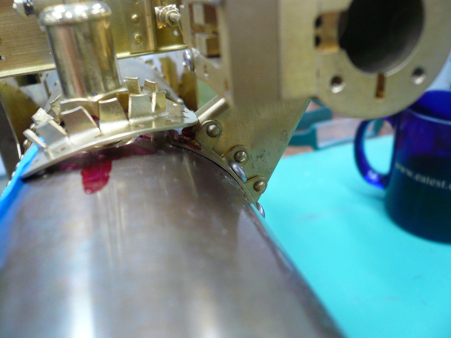
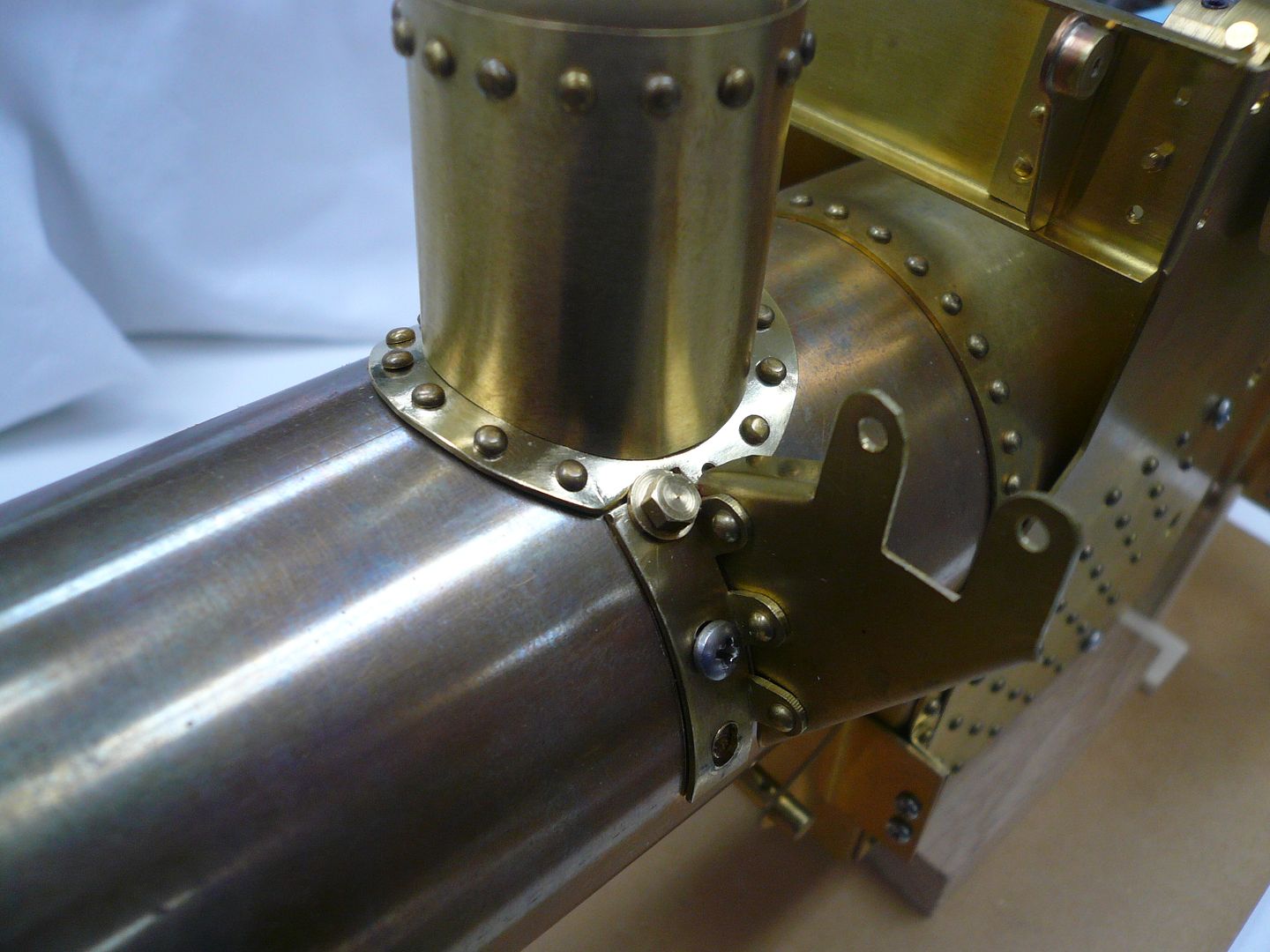
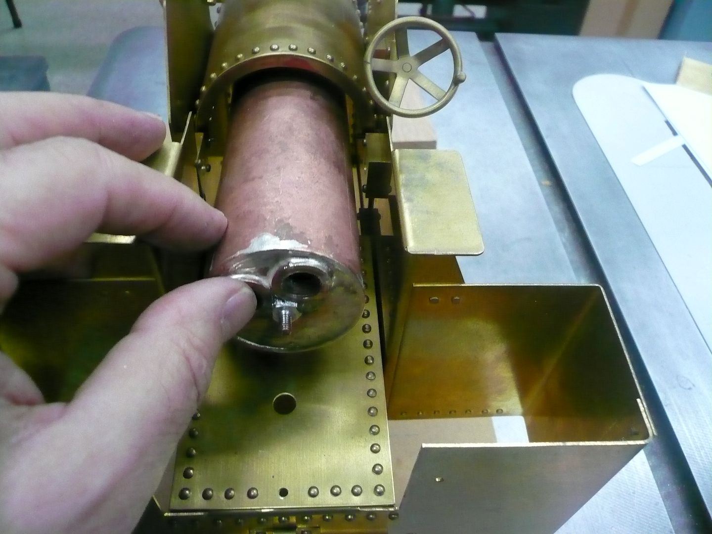
When I went to mount the flange on the boiler casing, I made this revolting discovery. The flange and cylinder mounting bracket had a serious interference problem.
P1060770.jpg


It was a case of making a change to the plans (bigger flange) without checking the impact on other parts. Both the flange and the mounting bracket needed to be modified, but to get the bracket off, all the engine components had to be removed. It wasn’t a major disaster, just a time consuming one.

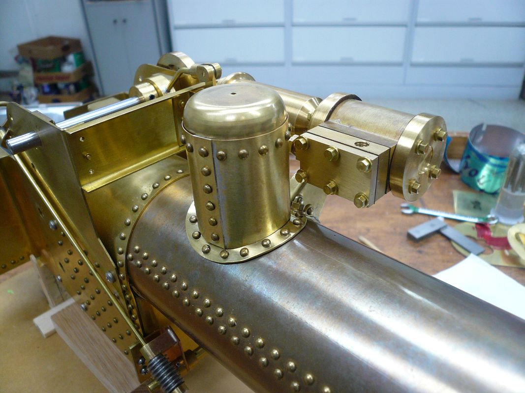
A little judicious trimming and I was back in business. This is one of those screw-ups that will pretty much disappear as more parts are attached.
P1060787.jpg


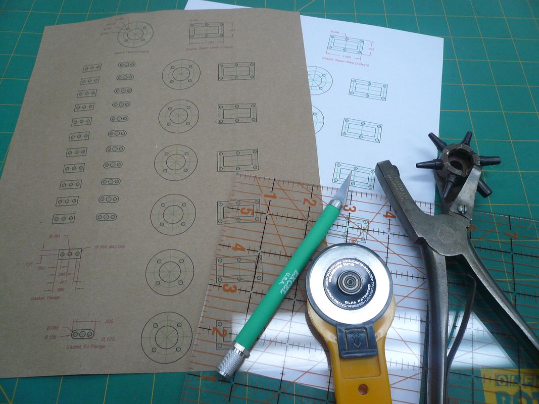
Since the engine was apart, I decided to do a final assembly when I put it back together (I'm really not naive enough to believe this will be the “final” assembly :)). This required gaskets. I used a piece of kraft paper shopping bag (Thank you, Doug Lanum) run through my printer to make mine. Here are my tools of choice.
P1060784.jpg


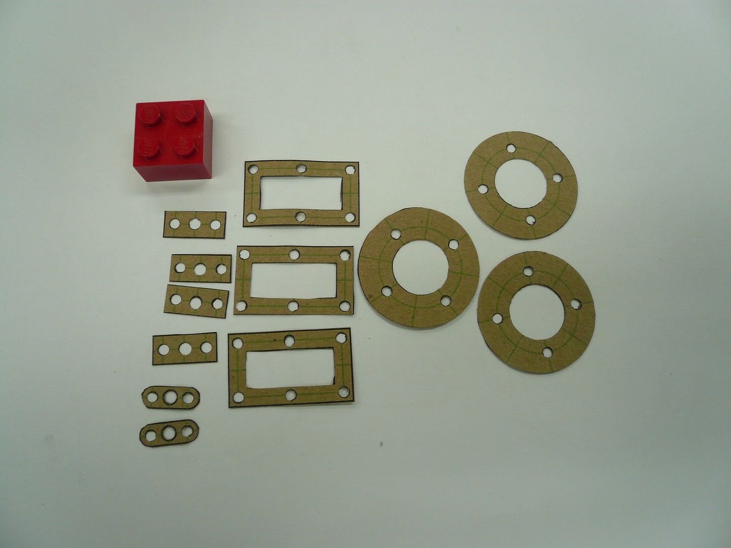
I got lucky in that the two small hole sizes exactly match two of the leather punch sizes.

The gaskets are about 0.007” thick and will be soaked with oil before installation.
P1060794.jpg


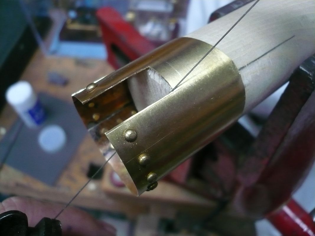
Also, slots needed to be cut in the steam dome for the throttle and the steam pipe. I used a jeweler’s saw with 4/0 blade and held the dome over a piece of dowel.
P1060850.jpg


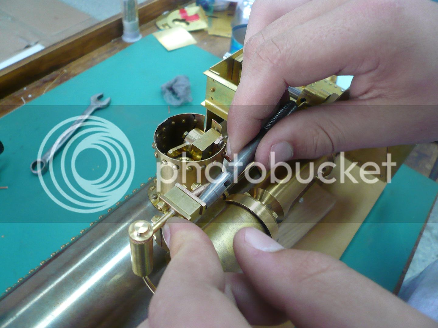
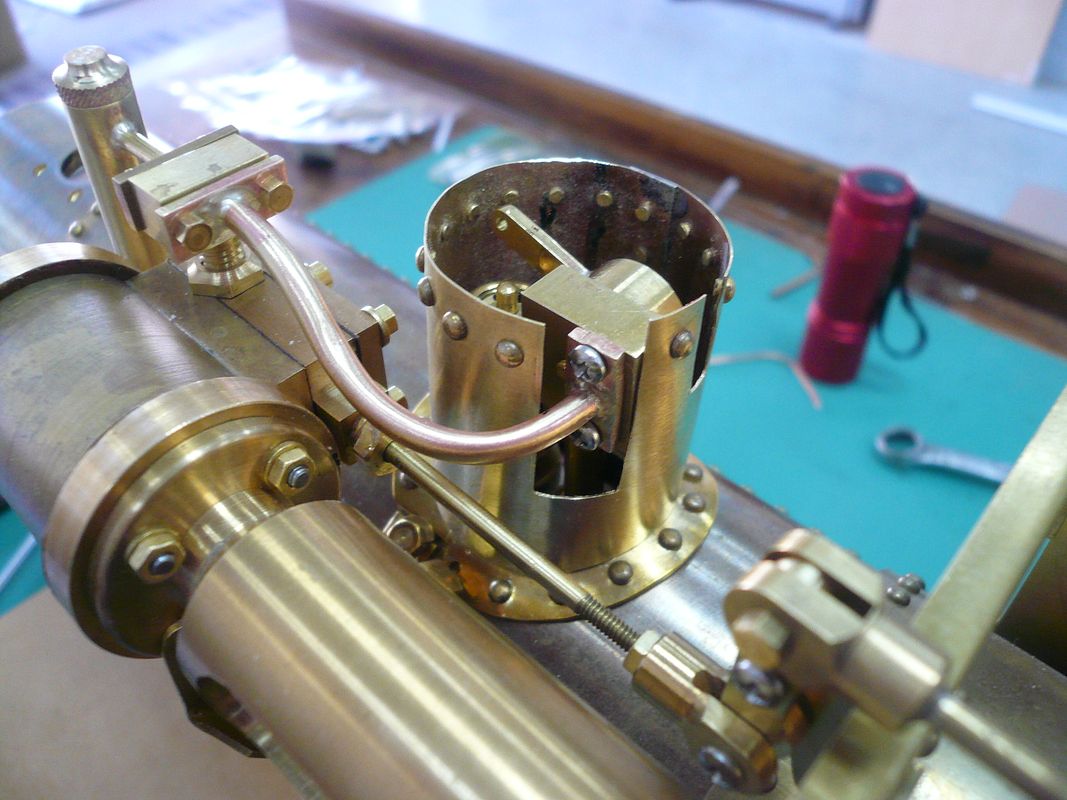
Re-assembly was tedious, but went fairly well. I used hex head screws this time just to make sure everything fit and that the screws were the right length.
P1060802.jpg


P1060851.jpg


P1060852.jpg


There isn’t much access to the steam pipe input attachment screws. A hex head is no-go and I can barely get them snug with a Phillips. I’ll try a socket head cap screw with a ball-end allen wrench but need to pick up some screws first.

If I would have stopped here, it would have been a good day. Unfortunately I didn’t.

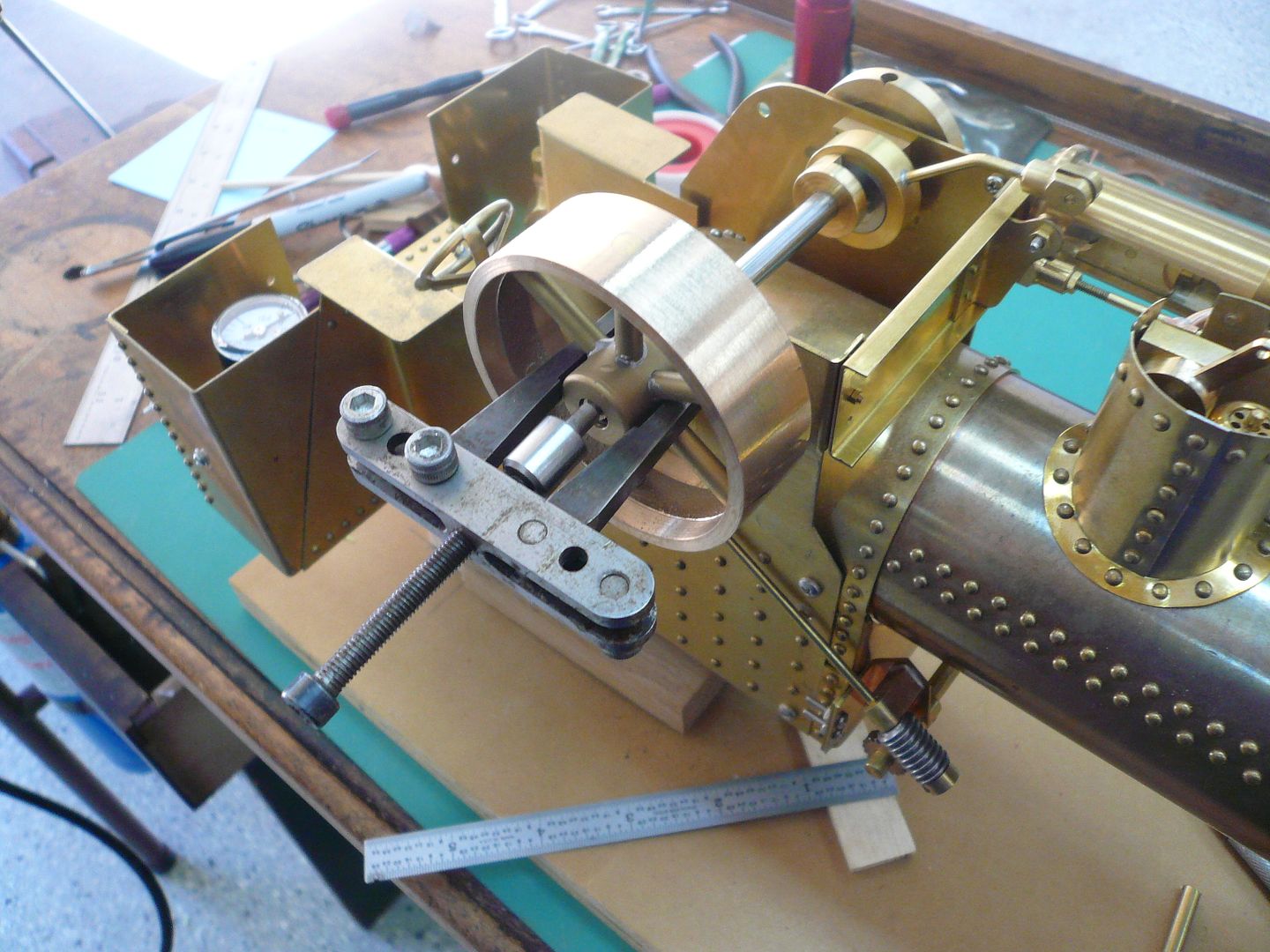
I assembled the rest of the engine (crosshead, connecting rod, crank, etc.) and decided to try installing the flywheel to see how everything turned. The flywheel was a very snug fit on the crankshaft, so I “wrung” it on. Rookie mistake. It went on about 3/8” and then would not budge not matter how hard I twisted on it. I then tried a puller, but had no luck either.
P1060858.jpg


Finally, I ended up removing the wheel and crankshaft together by taking off the connecting rod, crank, eccentric, etc. and pulling it out. I then literally had to beat the shaft out of the flywheel.

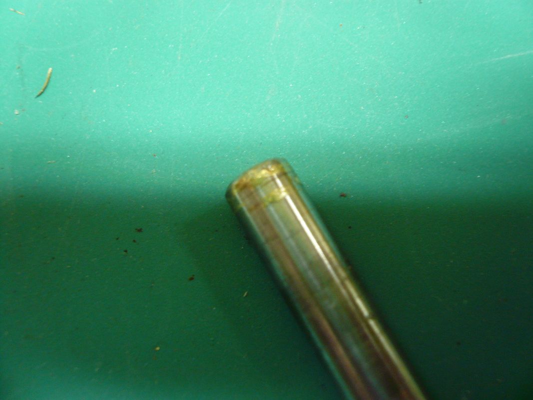
The end of the shaft had a one to one and half thousandths layer of brass welded to the end.
P1060861.jpg


I believe I’ve just had my first encounter with “Galling”.

Thankfully the flywheel survived intact and the crankshaft is just a piece of drill rod so, other than the experience, no real harm done. When I reassemble, I’ll ream the flywheel to a nice sliding fit and put a film of oil on before assembly. Experienced Hands:…Is there more I should do?

This experience also showed me that I needed flats on all the shafts where a set screw lands. I had a tough time getting the crank and eccentric off too because of small burrs the set screws raised.

That’s what I’m doing now: Reaming the flywheel and milling flats on all the shafts and axles.

Hopefully the next post will show a little more progress.

Regards,
Dennis
 
Dennis,

I have not commented much but I have been quietly following along. This is going to be one hell of a model when it's finished. :bow: :bow: :bow:

Best Regards
Bob
 
Well, we all learn about galling sooner or later, Dennis. A light push fit will cause it, especially when we have the almost irresistible urge to "screw it on" or wring it. Even a close running (rotating) fit can cause trouble if it is fairly long on the shaft.

You recovered from the boo-boos well, though, and it looks great in the trial fit ups.

To keep set screws from raising a burr on shafting, put a lead shot in the screw hole ahead of the set screw. I've used that method for a long time, and have never had one get stuck.

Thanks again for all the great pictures!

Dean
 
Nice! Nice! Nice!
And very happy the 'oh no!' turned out to be more of a 'drat'.
 
Great going Dennis !

I'll echo Bob:
This is going to be one hell of a model when it's finished.

Kind regards, Arnold
 
Vernon, Arnold, Zee...Thank you. You guys keep me motivated.

Bob...glad you're following along.

Dean...The lead shot tip is a good one. I had already milled flats before I read your posts. However, I didn't mill one on the eccentric collar because I figured I'd need flexibility for adjusting timing. I figured I'd just have to live with a burr. The lead shot will eliminate the problem.

Post #44

Plumbing the Boiler

The boiler slips into the boiler housing from the back.
P1060703.jpg


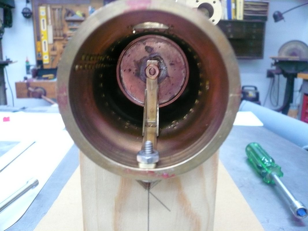
It’s held in place in the front by an “L” bracket screwed to the boiler stay stud and to the boiler housing.
P1060710.jpg


The plans put the boiler housing screw at the very front edge of the boiler housing. That causes the screw to interfere with the smoke box door, so a recess has to be milled in the door (also noted in the plans). All of that can be avoided by moving the hole back 1/2” which I recommend.

There looks like plenty of room around the boiler, so I plan to add a layer of 1/8” insulation before final assembly.

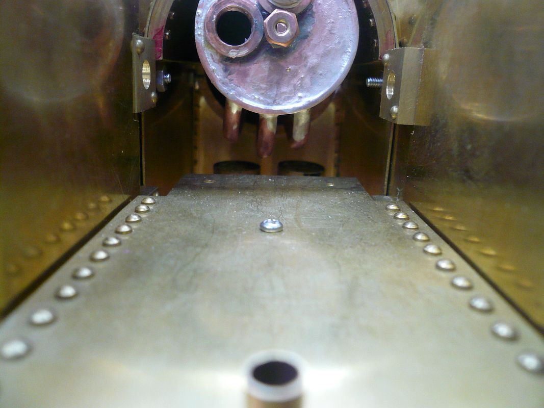
Here’s a view from the back showing the relationship between the boiler and the top of the burners.
P1060696.jpg


The rear of the boiler is bolted it to the firebox back sheet by the rear boiler stay stud. Nothing is tightened down in this shot, so final alignment will be better than it looks here.
P1060819.jpg


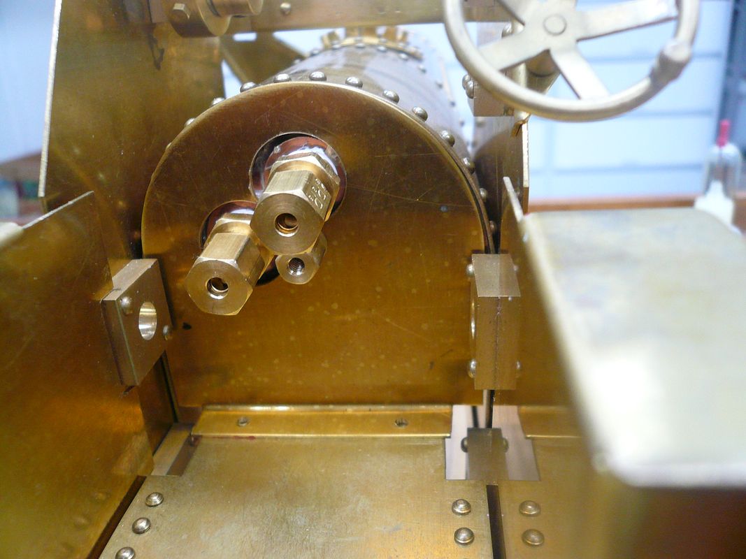
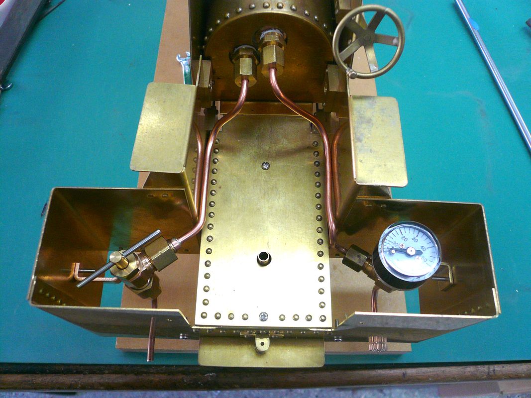
Boiler plumbing uses 1/8” copper tubing and compression fittings. The upper boiler fitting goes to the pressure gauge and the lower to the water inlet/test valve. The center piece that looks like a small fitting is the nut on the boiler stay stud. It had to be made extra long because there isn’t enough clearance around the fittings to get a wrench on a standard height nut.

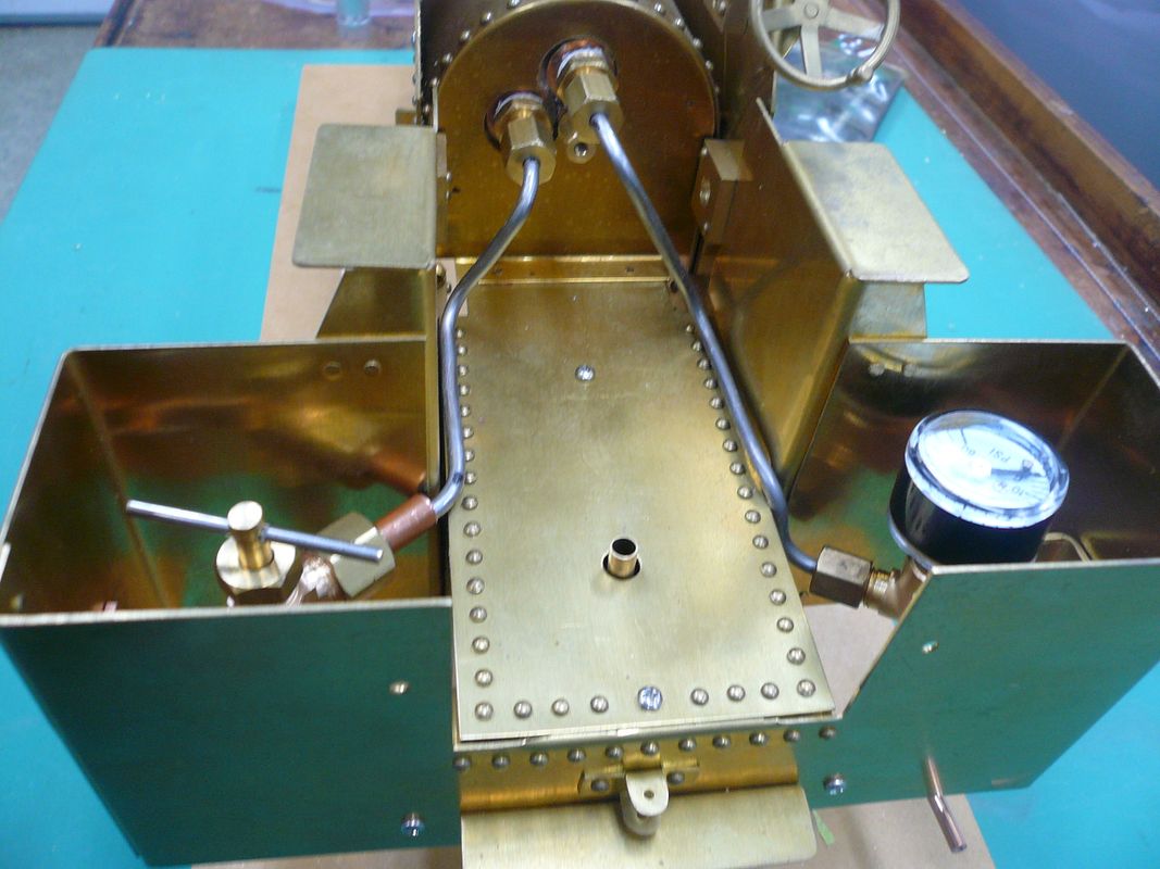
The test valve and the pressure gauge are mounted in the right and left coal bunkers respectively.

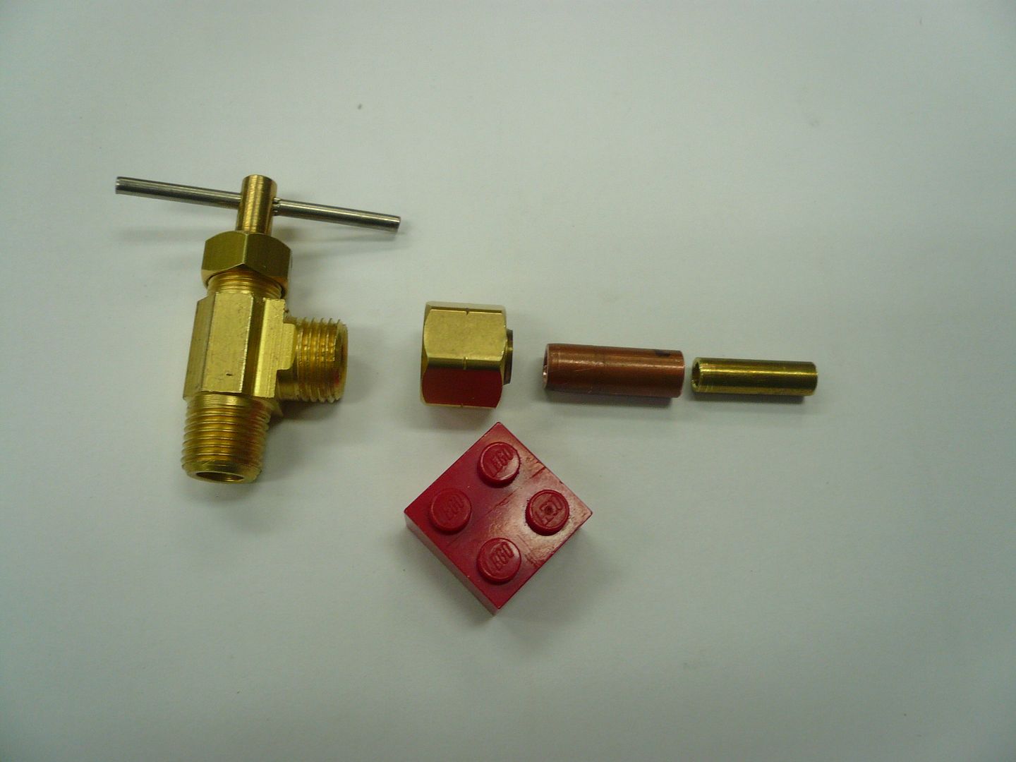
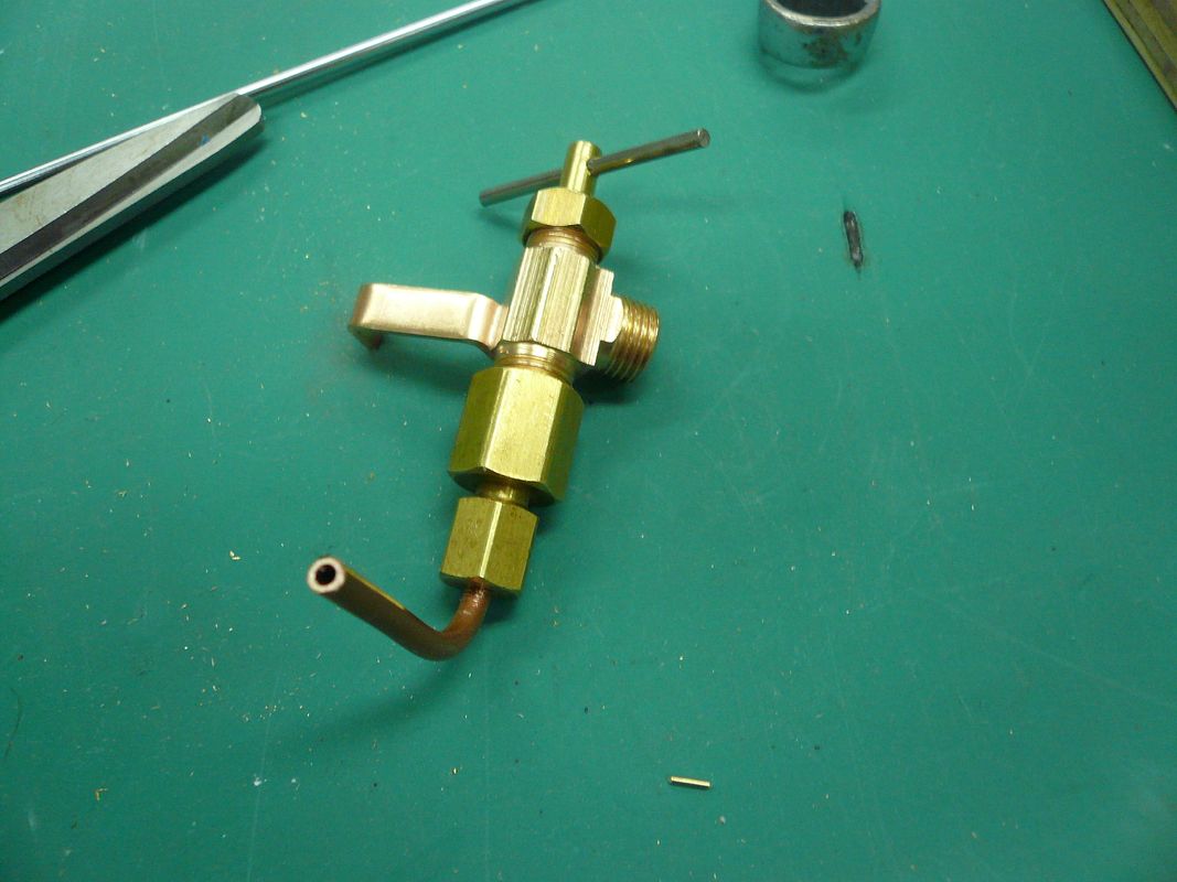
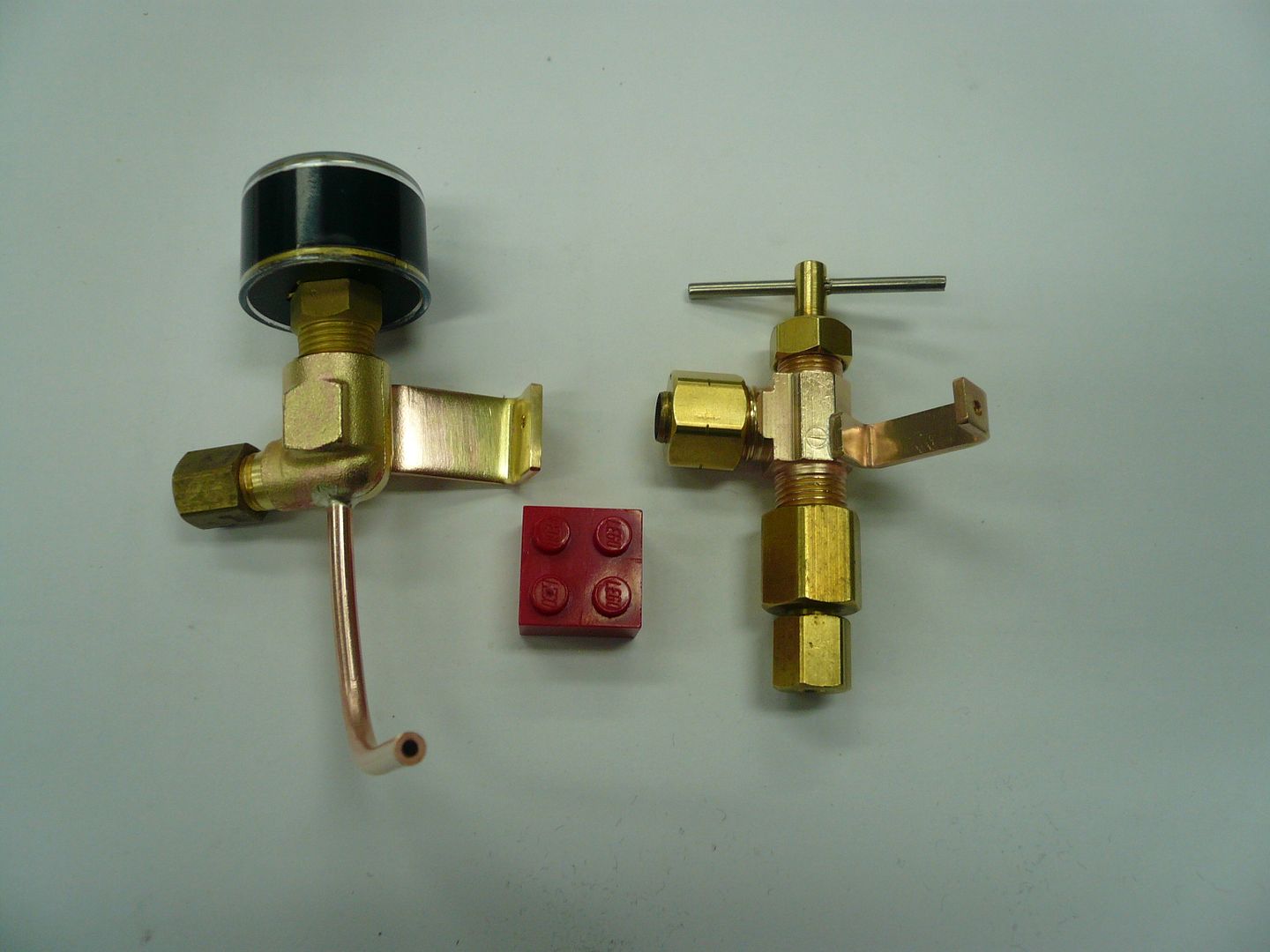
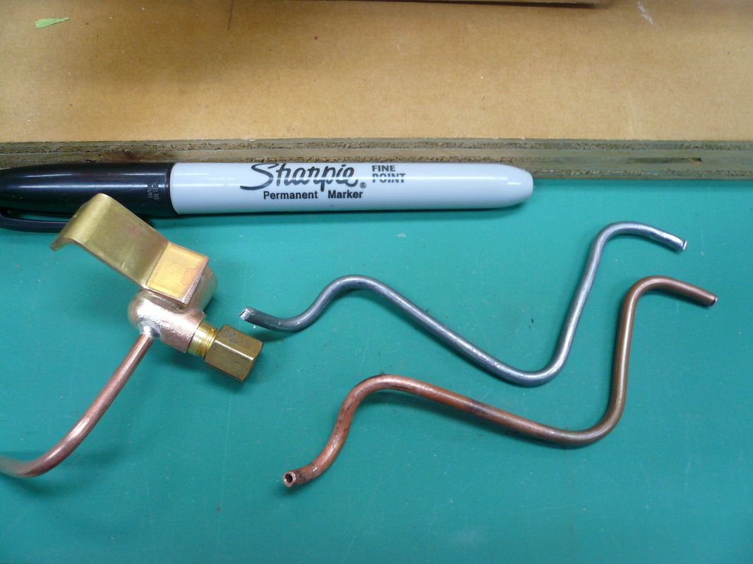
The test valve is a standard “humidifier” valve available at any hardware store. It’s made to use with 1/4” tubing. There isn’t room for a reducing coupler on the outlet side so an adapter (two pieces of nesting tubing) has to be made to connect it to 1/8” tubing.
P1060814.jpg


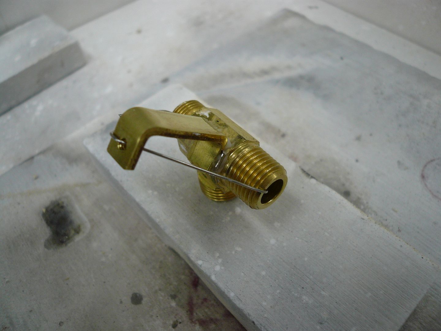
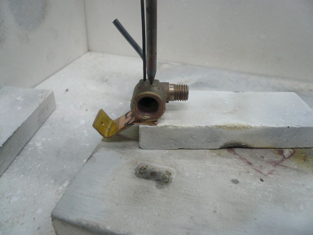
In addition, a mounting bracket has to be made and silver soldered to the valve body. Here's mine wired in place and ready for solder.
P1060829.jpg


And here’s the completed test valve assembly.
P1060848.jpg


The copper tubing extends out the bottom back of the tractor and is used to attach a syringe or pump for filling the boiler.

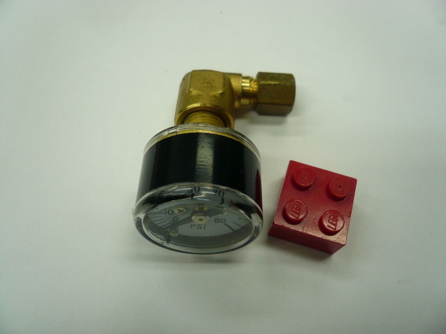
The pressure gauge I’m using is a “Live Steam Miniature Pressure Gauge” that I got from AK Enterprises (www.livesteamsupplies.com). About $10 as I recall. It’s 0-60psi and has a 1”dia. face instead of the usual 1 1/2”. There’s room for a 1 1/2” dial, but it’s a tight fit. The elbow is 1/8-NPT to 1/8” compression.
P1060817.jpg


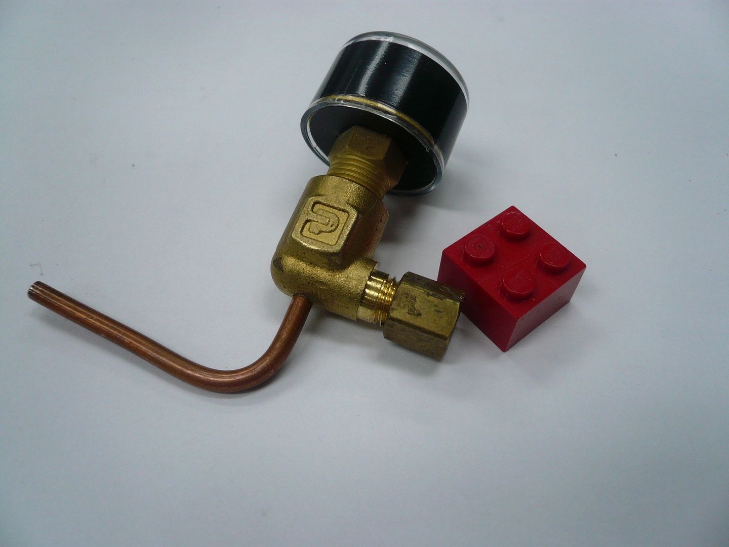
I made one modification to the plumbing that I hope will simplify operation. The tractor is designed to have a pre-measured amount of water pumped into the boiler via the test valve fitting. It seems like that’s less than ideal because you’re trying to push water into a sealed vessel. Some guys loosen the pressure gauge fitting at the boiler to vent it and then pump water in until it comes out of the pressure gauge fitting. I’m taking this a step further and adding a vent valve at the end of the pressure gauge line. It's made by drilling a hole in the elbow and silver soldering in a piece of tubing.
P1060822.jpg


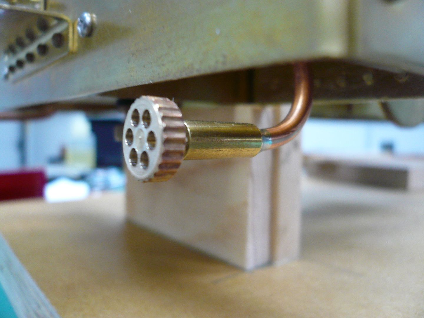
The tubing will have a screw-in plug attached to it and will extend out under the right coal bunker. In operation, I’ll remove the plug and pump water in the test valve side until it comes out of this tube, then close the test valve and replace the vent plug. (It should be noted none of this happens with the boiler hot or under pressure!)

The pressure gauge assembly also needs a mounting bracket. It's silver soldered to the side of the elbow. The bracket and the tube were soldered in the same heat.
P1060835.jpg


Here are the two finished assemblies less the outlet plug on the pressure gauge assembly.
P1060839.jpg


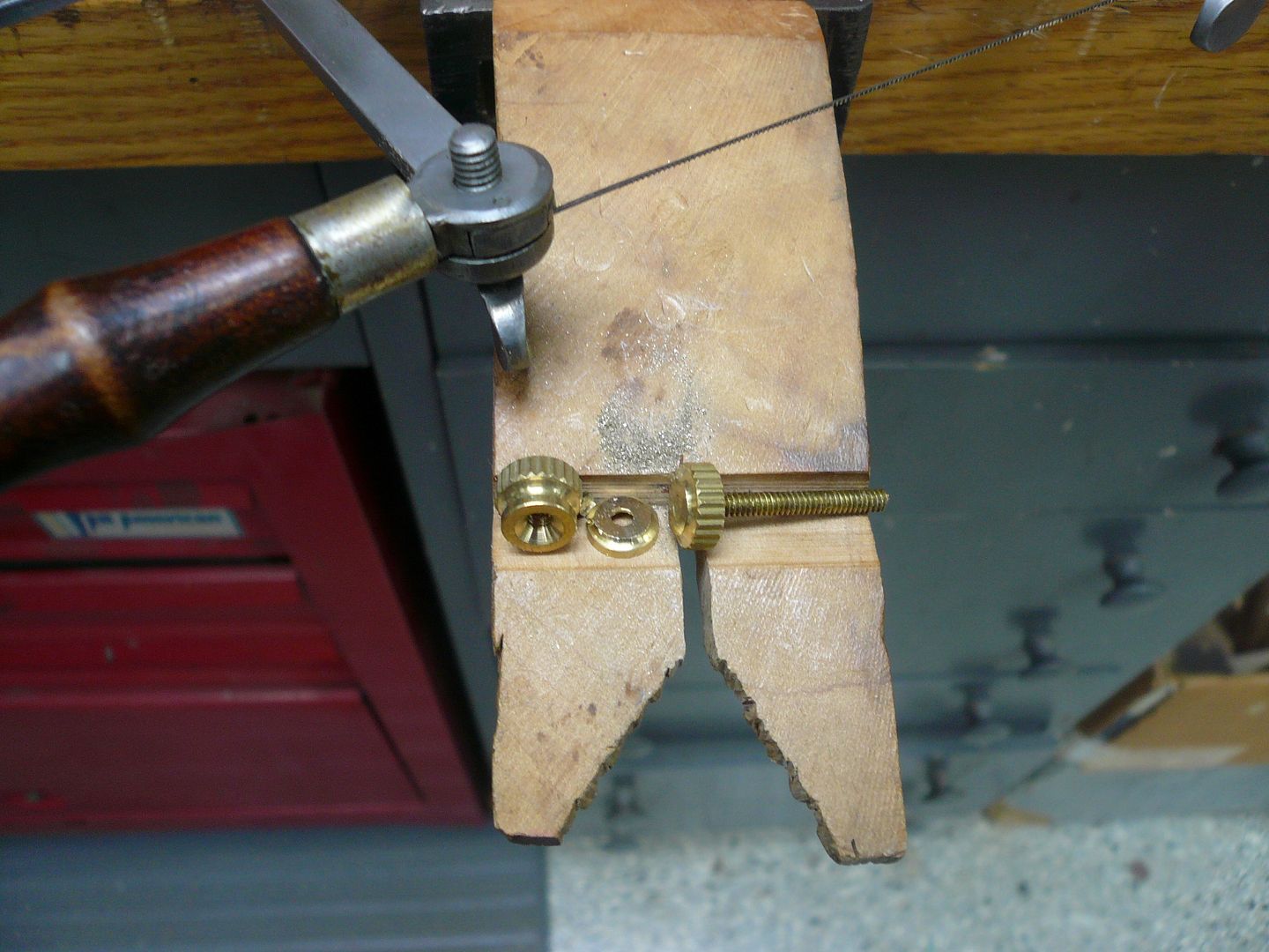
The outlet plug sleeve is a piece of 3/16 brass drilled 1/8" dia. halfway through with the other half tapped 4-40 to accept a threaded plug. The plug is made from an electrical terminal nut with the bottom cut off
P1060824.jpg


and a pointed piece of 4-40 threaded rod. The rod is silver soldered in place, the top is faced in the lathe and six decorative holes added. I used a piece of threaded hex stock in lieu of a rotary table to drill the holes. The point of the plug seats in the end of the piece of copper tube.
P1070058.jpg


The test valve and pressure gauge assemblies were then mounted in the coal bunkers. I used 1/8” soft solder to lay out the pipe locations.
P1060840.jpg


The solder is a lot easier to manipulate than the tubing and it’s easier to bend the copper against a pattern.
P1060844.jpg


I used the “groove in a round piece of stock” method to bend the tubes, but the first thing I’m going to do once this tractor is finished is make one of George Britnell’s tubing benders.

Here’s a view showing everything snugged up and in place.
P1060868.jpg


I’ll need to add some wooden dowel sleeves to the handle of the test fitting to avoid burnt fingers.

Regards,
Dennis
 
Dennis:

Your build just keeps on getting better and better. I'm running out of superlatives! :bow: :bow:

Still happily following along,

Joe
 
Dennis, your work is clean and meticulous. I would venture to say that this will be the nicest version of Rudy's steam tractor. Excellent!!
George
 
It sure is looking nice, Dennis. Your work is consistently impressive. No short cuts, no hacking,
inspirational, and a genuine pleasure every time you add a new post to your thread.
On top of all that, your photography is first rate, too.

I remember a post not to long ago, and I think it was one of yours, where you told what kind of material you used for your soldering hearth. Would you mind repeating it, and where you bought it?

Thanks,

Dean
 
Dennis,

Just Beautiful Workmanship. :bow:

Following your build closely...

Jeff
 
I can only associate myself to the others Dennis, you're showing great craftsmanship and following this thread is a real pleasure

thanks for sharing
 
Joe, George, Zee, Jeff and Ariz, Thanks for the comments.

you told what kind of material you used for your soldering hearth. Would you mind repeating it, and where you bought it?

Dean,
I used something called "Solderite" pads. I got mine from a guy at a swap meet, but they're available online. They come in 6x6, 12x12 and 6x12. I made my hearth 12x12 with 4" sides so I used one for the base and sliced one into 4x12 pieces for the sides. I've been very happy with them.
Dennis
 

Latest posts

Back
Top