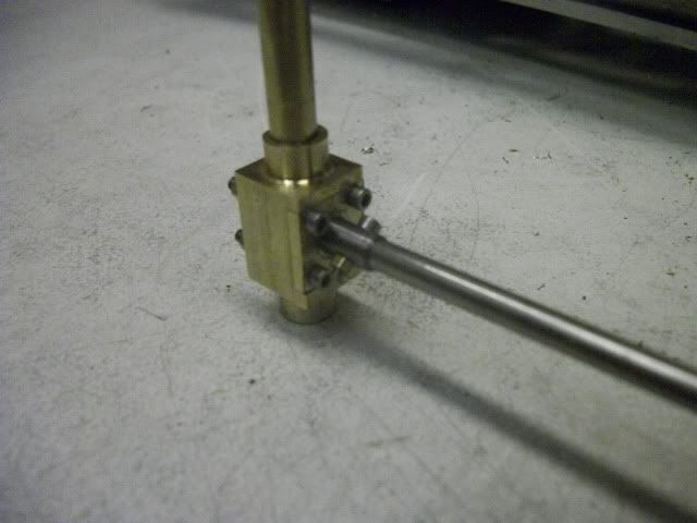
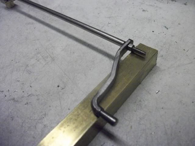
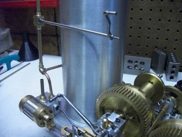
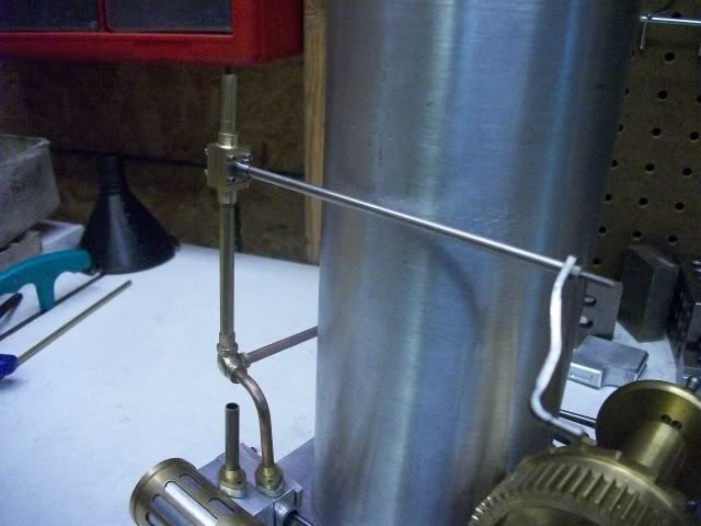
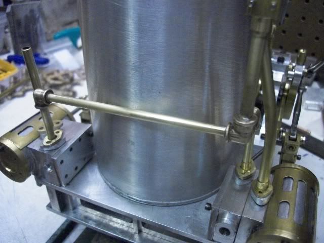
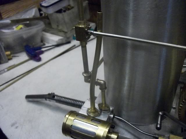
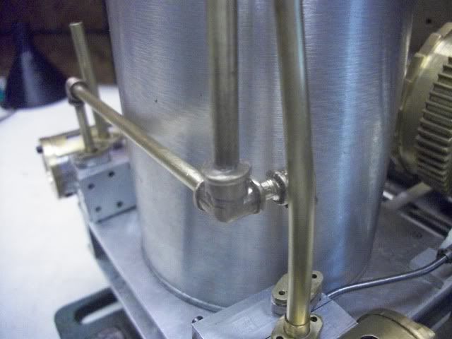
Thank you Kevin and Miner49er for the kind comments, and thanks for leaving a note that shows you are watching.
Thanks Jason for the critical comment. This forum needs a little more of that. It is easy to say "nice job" and much harder to say "think again". So I thought about it. My solution wasn't all that great. My next one may not be either.
I got into this situation by lack of experience and lack of forethought and choice of a scale (1:12) that makes some of the finer points of the model very difficult to reproduce. I started with the larger parts of the project when I should have given more thought to the smallest. If I had chosen a larger scale, I wouldn't have this problem.
Pipe size:
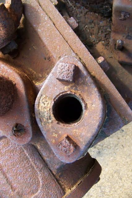
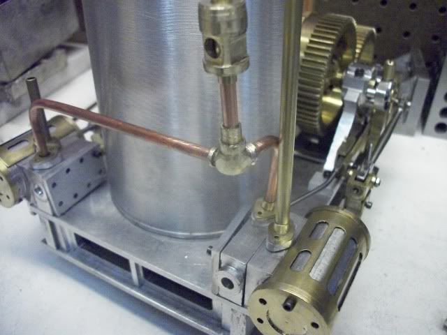
This is the steam pipe on the port side. I measure it at 2" OD which at 1/12 scale equals 1.67" so I will use 5/32" tube for air in and 3/16" for exhaust. I might have been better of to choose 3/16" inlet and 1/4" exhaust. Then I could use the PM research cast elbows, but for some reason they just look too big to me.
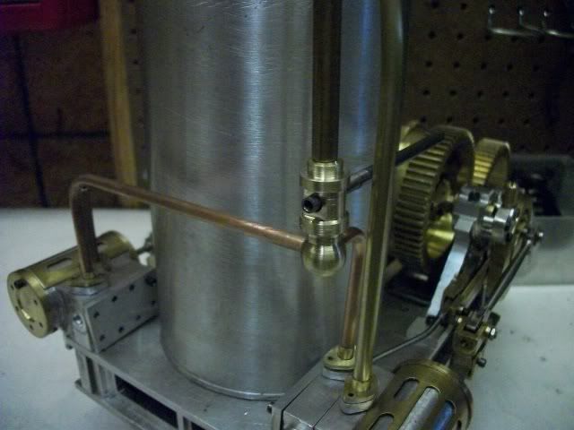
Can I do any better? Probably not but I tried. Here is the results of a lot of filing on a three way elbow. Does this look better?
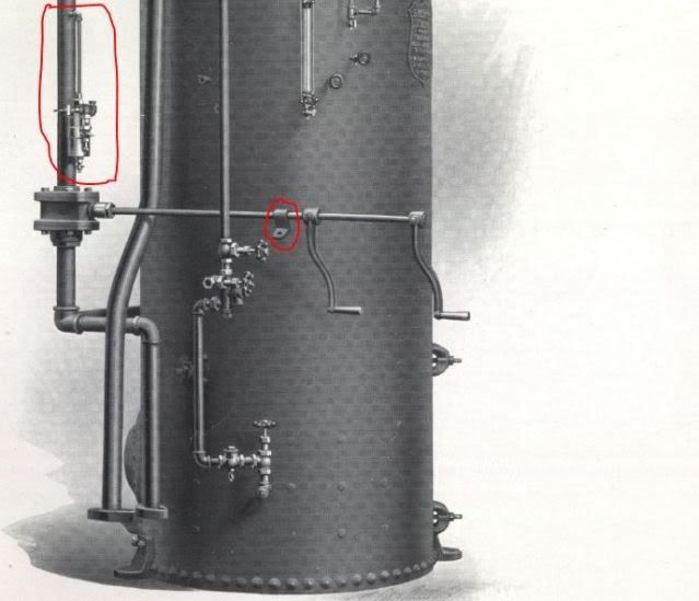
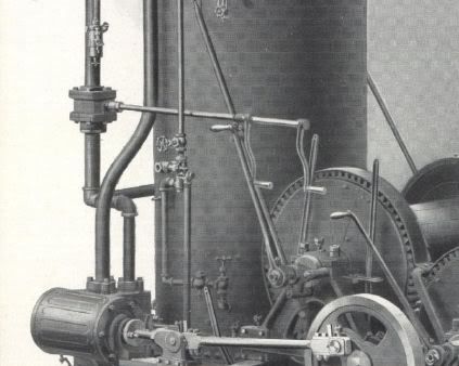
Here is another cut from the brochure. It seems to show that there is a bracket of some kind that supports the shaft of the steam control on the boiler stay. I circled it in red for emphasis. The other item that is circled in red on the steam pipe above the control valve is a mystery to me. What is it?
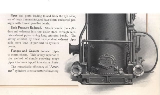
While taking a look at the brochure, it is clear that "truth in advertising" was not all that important at the time. Do the gentle bends of the exhaust pipe really add 17% to the power? At the top of those pipes with the gentle bends is a 90° elbow. Does that help or hurt?
The next paragraph shows how important AMHOISt thought the flanges were. I couldn't think of any other way to make it work. The piping can be assembled and then bolted to the cylinders.
I am still undecided on this.
Jerry




![MeshMagic 3D Free 3D Modeling Software [Download]](https://m.media-amazon.com/images/I/B1U+p8ewjGS._SL500_.png)


