Building Fred

Home Model Engine Machinist Forum

Help Support Home Model Engine Machinist Forum:

This site may earn a commission from merchant affiliate links, including eBay, Amazon, and others.
nkalbrr, Zee & Dean - Thank you for checking in guys :)

nkalbrr - I wasn't very particular with the rail - just as cheap as I could get ;D. I downloaded the plans from the john-tom site; it's the Dave Watkins DeWinton. If you're interested in building it, I would seriously recommend Dave's build "log" document as well; you can find it on his home site Here as "Idris Story". I'll be building a sort of "outside" RR on my front porch ;)

Zee, thank you; it is an enormous bonus to know that some of my work can actually inspire someone - and to be told so is great honour. :)

Dean, my thoughts exactly; I anyway have to make a jig to hold the screws for slotting for the countersink ones and making hex heads on the visible ones.

Kind Regards, Arnold
 
Some more work done on Fred.

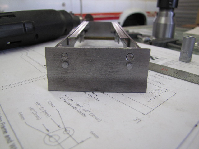
I cleaned up the screws pretty much like Dean suggested with a jig with a tapped hole. While tapping to depth I felt a little "kgr" - when I took the tap out, a couple of teeth were missing. So that's the end of my set of 2mm taps. I slotted the countersink screws with the Dremel with a thin cutting disk. The bottom ones in the photo still need their hex heads finished. Made a ****oo on the one countersink hole in the end plate; it is too deep. Fortunately this will be hidden when done:
s0087.jpg


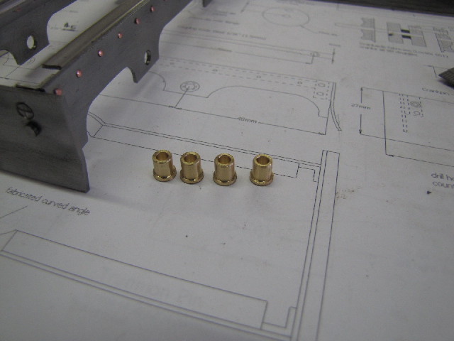
Then I turned up the axle bushes:
s0090.jpg


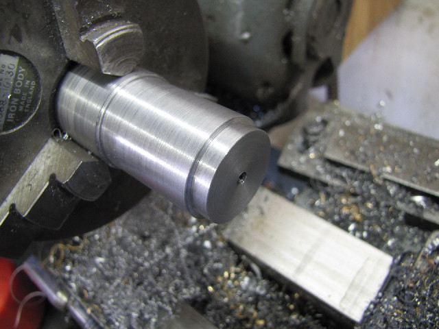
Started turning the first wheel from HRS; that's all I have in this size:
s0096.jpg


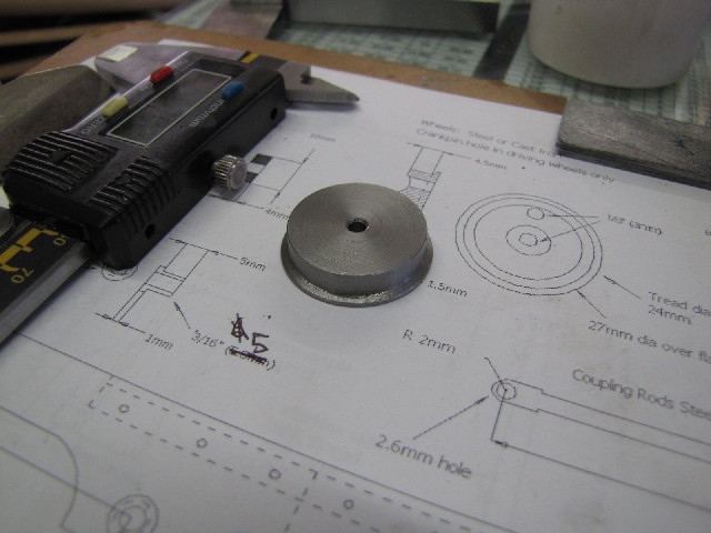
First wheel done:
s0097.jpg


Then I finished another wheel. While parting it off, I went a bit quick and snapped the tip on the parting tool. So I just took the chuck off the lathe, and clamped it in the bandsaw to finish the cut. Would have put in effort with the hacksaw on the lathe, but clean out of hacksaw blades... I'll re-grind the parting tool tomorrow.

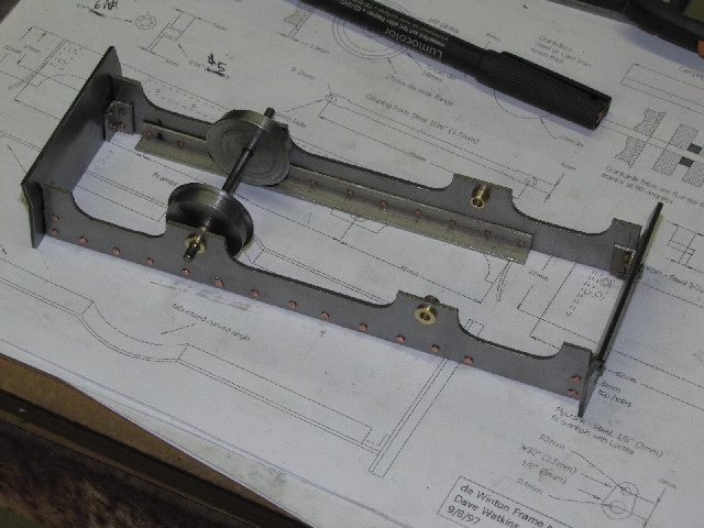
Then I pressed the bushes into the frame, and cut the plain axle from piano wire. Made a mock-up assembly & stopped for the day:
s0099.jpg

Both wheels still needs a final facing on the back side. I'll do that once all the wheels are complete.

Regards, Arnold
 
Neat! Wheels. Wheels are always a good sign, Arnold. Kind of like a little stepping-up point where the bare frame gets to go mobile!

I remember from your earlier posts on this project that you used some mongrel iron. And then you are having trouble breaking taps. I wonder if the iron was a little hard.
Here in the states, once in a while I'd come across an old bed frame, which looks like it's just made of angle iron. It was something other than a common mild steel, though. It was quite hard, and I could barely drill through it, and the drill bit really didn't like it.

Sounds like what you have here for your loco frame.

Dean
 
Nice Arnold. Are you going to be doing any kind of finishing on the wheels? Like blackening or something?
 
Dean, Zee, Rob - Thanks for looking in :)

Dean, I _think_ what I have for the angle in the frames is some kind of stainless; it work hardens very quickly if you work slow; it wants to be worked aggressively, then it actually machines quite well. The irony of it all is I found some brass angle last week; was looking for some tile grout, and the tile supplier have brass angle for edging for tiles :Doh:

Zee - trick question; to be honest, I haven't even thought that far... Most likely I'll just paint them with the same high temperature black paint that I bought for the loco.

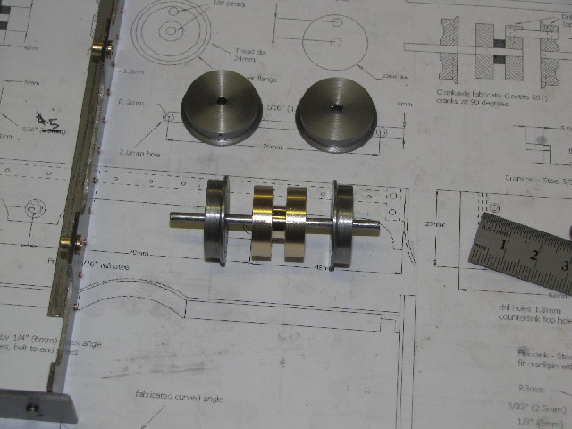
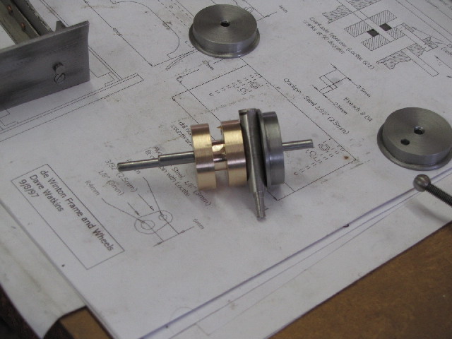
Today I finished the other wheels. The plans call for two separate crank webs from steel and a spacer to go between them; I just made that lot as one part out of brass. I still need to drill the web and 2 wheels for the crank pins:
s0104.jpg


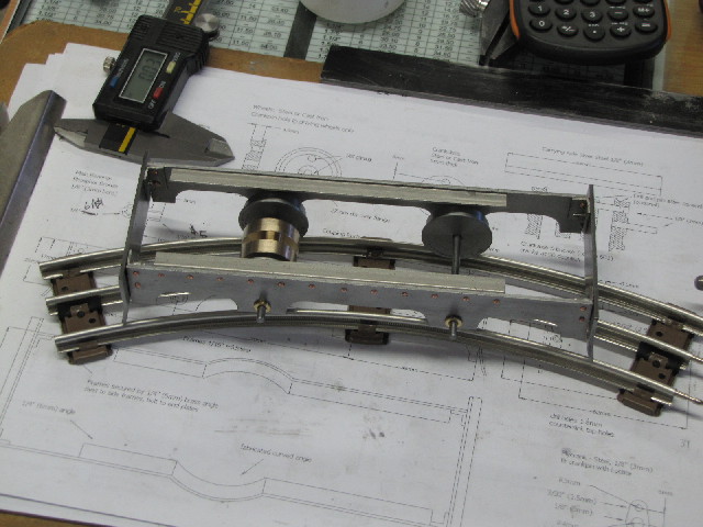
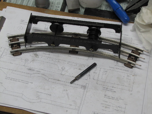
Quickly cut another piece of piano wire axle & assembled everything. I just had to see what it looks like on a piece of track ;D:
s0106.jpg


Regards, Arnold
 
Hi Arnold

Good work Arnold


Its a good idea to get the tread on the wheels all exactly the same size so that you get good traction, this is easy done just turn yourself a mandrell, with a thread on the end, that a neat fit on the wheels don't take the mandrell out of the chuck, slip a wheel on the mandrell tighten the bolt take a small skim off the wheel, clamp cross slide up, they just take the same cut across each wheel in turn, they will all be exactly the same. This is what I did on my loco build.

Cheers

Stew
 
Careful Arnold. Don't make the same mistake I did. (As Marv said...if you rush, the Jabberwockie will get you.) ;D
 
Hi Arnold, love your loco project. it's looking really good.

Nick
 
Thanks for the links. You are making great progress on the locomotive.My question is what kind of cars is she gonna tow?
 
You make good progress each time you get to work on it, Arnold.
I looked this loco up using google, and see that there are a couple of different versions. One has the steam cylinders up front, and inside the sides of the frame, and one had the cylinders outside the frame, toward the rear. From your crankshaft, I'm guessing this is the first type? (Like I say, guessing.)

One site I came across noted that the Idris was a real loco in the mid 19th century. Didn't know that.

I've worked with a bit of stainless, but don't find it very pleasurable working it with my small machines. It wants a good feed rate for almost any kind of tooling, and that's something that can't always be achieved with a light lathe. It can be ornery stuff.

Anyway, it's still coming along nicely. The ones I saw on the web had a lot of charm, especially under steam, going 'round the track. This will be a fun one to see steaming down the line!

Keep up your good work!

Dean
 
Thank you everyone for the responses :)

Stew, that's a good tip on the wheels - thank you VERY much :bow:. That will be a definite when I build an 060 or 260 loco in future. Frankly, I think the lack of accuracy I already have with the frame on this build negates the accuracy needed from the wheels; they are all within less than 0.01mm in diameter. I need some more practice on frame-making though ;)

Nick & Powder keg - thank you :)

Zee, I'm not scared of any "Jabberwockie" - he caught me a couple of times already, and I know a BFH does not work to keep him away or at bay. But he is actually quite considerate; before arriving, he makes you feel sort of tired and "unconcentrated", and sometimes he puts a funny feeling in your stomach - sort of a subdued version of the feeling that I used to get many years ago when I was about to do something that I just _knew_ would end up with my dad taking a couple of firm whacks at my backside with a leather belt :) If you stop when you feel any of the Jabberwockie symptoms, he usually stays away, but he can and will arrive unexpectedly as well - in which case it's just another brickpart in the Wall ;D

nkalbrr, my pleasure :). I just want the live steam loco for now, and as it is based on a twin double-acting wobbling steam engine, it is relevant to HMEM. I'll build "mining" cars for it (see below) - but very likely won't post building those on HMEM, as it's not on-topic :)

Dean - Thank you & you're right; steam cylinders vertical & up front. And yes/no - Idris is, as far as I could establish, Dave Watkins' own name for the loco - I might be wrong though - but from my own research this loco is a variation on many real ones that was built by the De Winton company, and most of them used to carry slate trains from quarries. As to stainless, I don't have much experience with it; so far, turning was no problem. But that one "slow" hole I drilled was a bust!.

Kind Regards, Arnold
 
I made some progress on Fred again today:

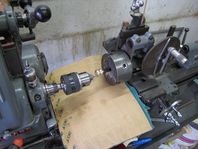
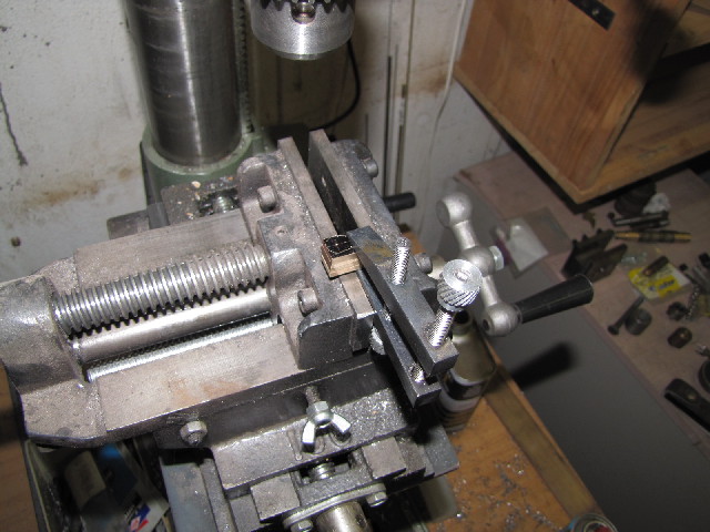
First up, I drilled the crank holes in the driving wheels & crank web. For this, I turned an arbor on the 3-jaw to hold the web / wheels, and set up the vertical slide & dividing head to drill the holes. I transferred the 3-jaw to the dividing head without removing the arbor to keep concentricity. Back when I made the web, I already punched it for the locations of the crank pins before dilling it through center. Here is the setup I used to drill the holes in the web; when this was done, I just clamped both driving wheels on the arbor and did them the same way:
s0116.jpg


Then I loctited the shaft & crank pins to the web, left it to set up a bit and then added the wheels to the assembly. I just used a piece of 6mm rod to get the correct spacing between the wheels & the web:
s0122.jpg


I also assembled the rear axle & wheels with loctite; it was easier to first put one wheel on in it's correct position, leave things to tighten up, and then add the second.

While waiting for the axles to cure a bit, I gave the frame a coat of paint, and when the axles were OK, the wheels as well. I used the black high temperature paint that I bought for the boiler on it, so I shoved everything in the kitchen oven at 120deg C to cure a bit. Fortunately, it appears that the "loctite" substitute I have held up to this temperature. When I reassembled everything, the axles were just a tad stiff in the bushes, so I made a 3.05 mm d-bit reamer and gave all the bushes a run-through with it. Now the axles are nice & free running without any play. Assembled, & the reamer:
s0123.jpg


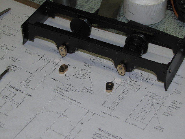
Next up, some work on the flycranks; I sawed 4 pieces from some flat brass I have. One I laid out to dimensions, clamped the whole lot together as a bunch & drilled the 3mm hole for the axles:
s0130.jpg


Then I just bolted them together through the drilled hole with a 3mm bolt before removing the clamp, and drilled for the flycrank pins. I pressed a piece of rod through the new hole, and took the assembly to the vice, where I filed the whole lot to shape & size. Once done, I just had to see what they looked like on the loco:
s0133.jpg


Regards, Arnold
 
Oh I am enjoying this tremendously. Well done A', and BRAVO! Thm: :bow: :bow: :bow:

BC1
Jim
 
Cool. You can't have too many live steam trains.
 
This is really an enjoyable thread, Arnold. You're coming along great.
The assembly so far looks nice all painted up, with its shiny brass flycranks. I can almost picture it steaming down the track!

Dean
 
Nice one Arnold :bow: :bow: :bow: :bow: :bow: :bow:
keep up the great work and post


Regards Rob
 
Zee, Jim, Shred, Dean & Rob - thank you all very much for looking in and all your positive comments ;D I't is really nice to have such support, as locally, I'm the only person I'm aware of doing this kind of thing, so there's no-one to share with here in Namibia.

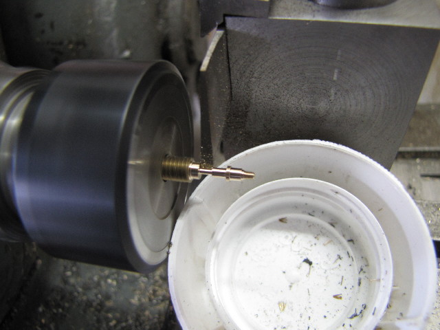
Today I made the crank pins for the flycranks. Once again I deviated from the original design - mostly to accommodate my tooling, but while doing this, I added a little shoulder that would prevent the coupling rods directly touching the flycranks while running. I think Dave added little washers between the coupling rods and the flycranks when he put his Idris together. So I made the crankpins with a section of 2mm thread for retaining nuts, a 2.5mm bearing section for the coupling rod link, a shoulder, and a 2mm section to press into the flycrank. In the next photo, I'm parting off one of the pins:
s0143.jpg


Next up, I made some nuts and filing buttons for filing the coupling rods - I didn't take photos while making these.
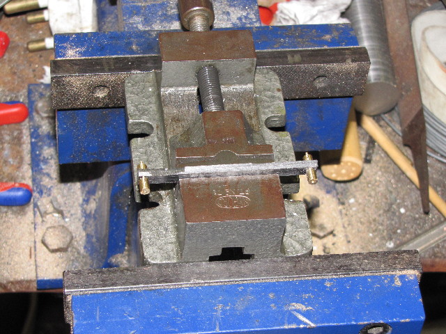
Then I marked out the top of two pieces of plate superglued together for the coupling rods, drilled & reamed the holes, and trimmed the assembly to approximate size on the bandsaw. I installed the filing buttons through the holes, and clamped my milling vice in the big vice, with the coupling rod assembly clamped in the milling vice, for filing down:
s0149.jpg


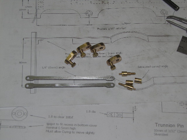
The results of today's work: flycranks with pins pressed & loctited in, nuts screwed on, a pair of coupling rods, and what's left of the filing buttons:
s0151.jpg


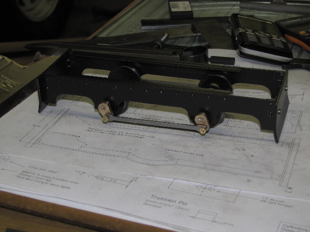
And mounted on the loco frame:
s0153.jpg


I was still wondering what I'm going to do about the flycranks' appearance, I quite like the contrast of the brass with the black, and after Dean's comment, I'm just going to leave them as-is, with a clear laquer coating for protection.

Regards, Arnold
 

Latest posts

Back
Top