Help Support Home Model Engine Machinist Forum:
This site may earn a commission from merchant affiliate
links, including eBay, Amazon, and others.
It is a little hard to tell exactly how the power was taken off of some of these Cretors, but in one case, clearly a chain was used.
In a photo of different engine, perhaps shafts and gear drive?
It is also clear from the video above that the Cretors was not balanced very well.
I think a properly sized counterbalance weight in the crank disk would stop most of that horizontal motion.
Design Engineer
Project of the Month Winner
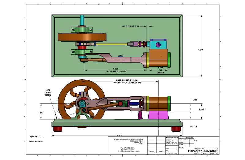
Yes, I'm definitely liking it better with a 3.5" flywheel mounted between the bearing towers. There is just enough room for an eccentric with a hub off to one side and the flywheel between them. Tomorrow I will start posting drawings of everything. I have everything built now except for the base and the crosshead guide and the flywheel.
Design Engineer
Project of the Month Winner
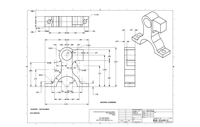
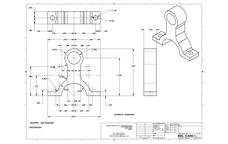
Okay---Here we go!!! These drawings are based on Stew Harts drawings of the Popcorn Engine. I have redone them so that 99% of the tooling required to build this engine is British Imperial "inch" measurement. The exception is the steam ports in the cylinder, for which you will need a 2mm and a 3mm endmill (preferably 2-flute). If many of the dimensions seem a bit "wonky" its because they are direct "hard" conversions from metric. I have built the parts from every drawing that I post here, except for the flywheel and the crosshead guide and the base. I will post these parts when I complete machining them, just to confirm that the parts do indeed match the detail drawings. The first two drawings are the bearing stands. Nothing to "trick" about them, but fussy little buggers to make, just the same. I managed to somehow screw up and make one of mine about .030" too short, so I will have to put a shim under it. There is far too much work in the darn thing to remake it!!!
I WILL BE POSTING A LINK TO DOWNLOAD ALL THESE DRAWINGS AS .PDF FILES WHEN MY ENGINE IS UP AND RUNNING.
Design Engineer
Project of the Month Winner
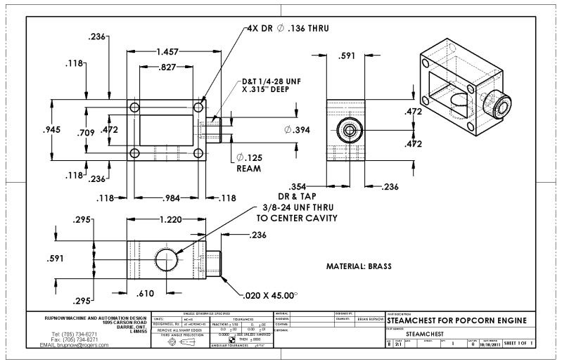
There is nothing too exotic about the steam chest. I made it from one solid chunk of brass, used a 1/8" drill in the 4 inside corners, then squared the inner corners up with a file after the fact.
Design Engineer
Project of the Month Winner
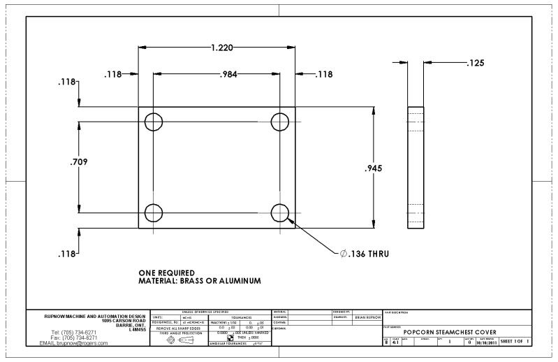
The drawing of the steamchest cover calls for it to be made of brass, however I have made mine from a peice of 3/16" clear lexan because I want to see that valve working.
Design Engineer
Project of the Month Winner
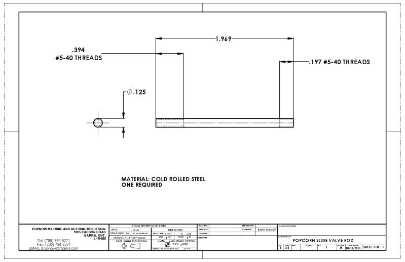
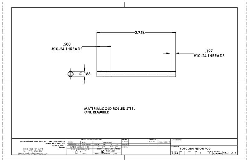
All of the linkage rods are pretty straightforewars stuff, all made from cold rolled steel rod. The only observation I have is that I need to buy a new #10-24 die, as mine seems to be almost too dull to cut---however that won't effect you.
Design Engineer
Project of the Month Winner
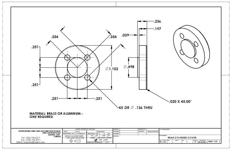
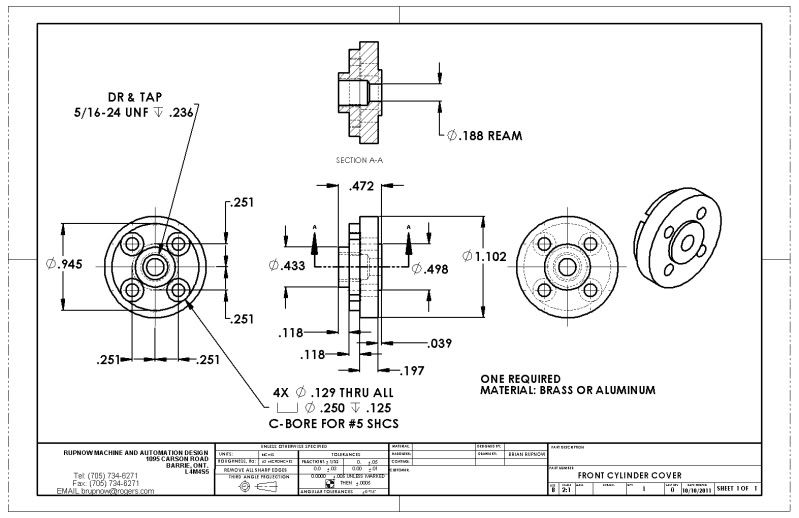
The rear cylinder cover is exactly as per drawing, nothing unususal about it. The front cylinder is different than Stews, as I chose to use shcs in it to clear the crosshead guide.
Design Engineer
Project of the Month Winner
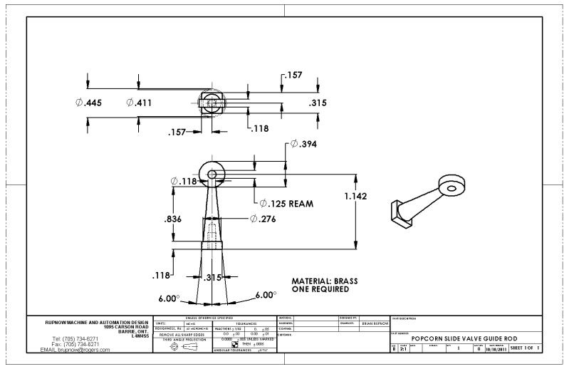
Nothing to say about this little guy, other than be sure to hold that backing dimension tightly---It has to line up with the bore in the steamchest.
Design Engineer
Project of the Month Winner
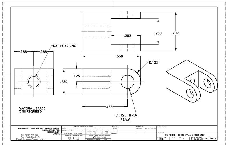
These two connectors for the valve rod were built exactly as per drawing, except I built the smallest one from steel because I had a peice of 1/4" square cold rolled stl. laying around.
Design Engineer
Project of the Month Winner
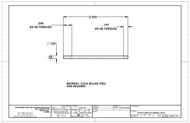
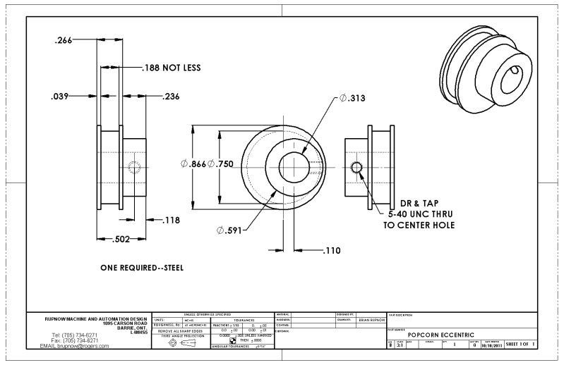
I built the exxentric as per Stew Harts drawing, then figured out after the fact that it would be a LOT easier to adjust the valve timing with an offset hub and set-screw to let you access the set screw without having to remove the eccentric strap to do so, so thats how I made the drawing.
Design Engineer
Project of the Month Winner
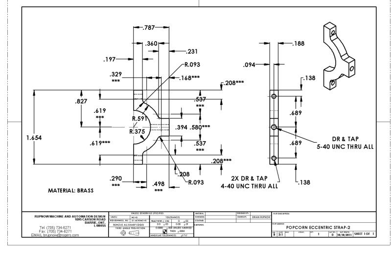
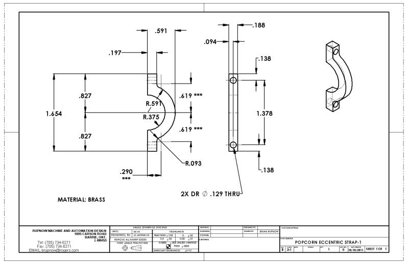
The eccentic strap--(two peice)
Design Engineer
Project of the Month Winner
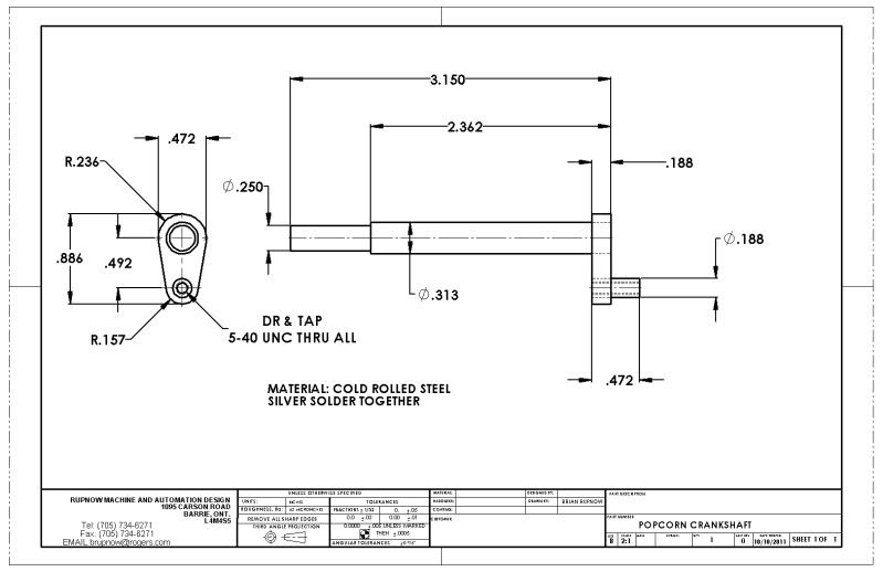
Nothing real exotic about the crankshaft, except that I siver soldered mine, while I think stew Loctited his together.
Design Engineer
Project of the Month Winner
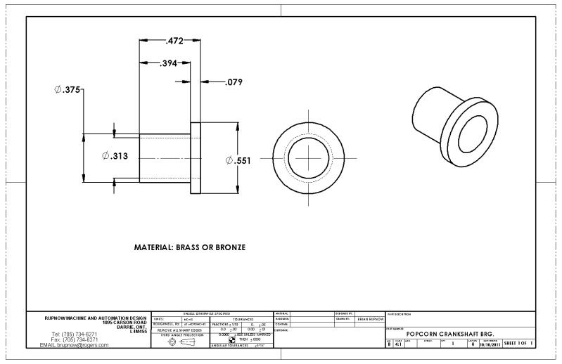
I made the crankshaft bearings from brass, exactly as you see them.
Design Engineer
Project of the Month Winner
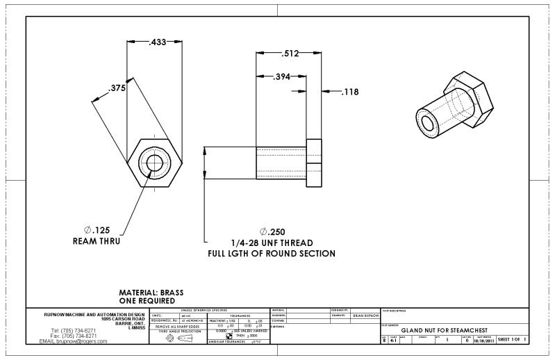
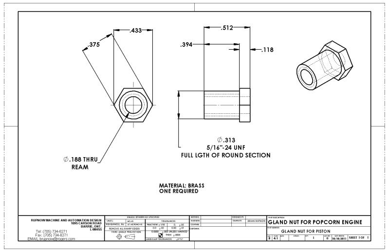
The two "glands" I made were made using 7/16" hex brass because I had some in stock. The drawing calls for 3/8" stock, which might look a little more to scale with the rest of the engine.
Design Engineer
Project of the Month Winner
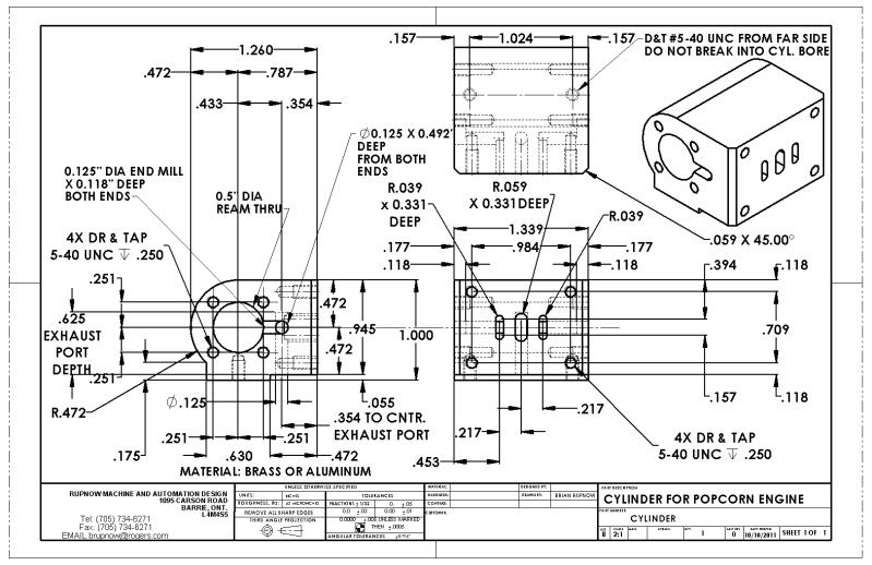
The cylinder---What can I say, except, Jeez!!! There's a lot of work in that thing!!!
Design Engineer
Project of the Month Winner
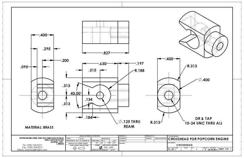
Crosshead---Just as you see it---
Design Engineer
Project of the Month Winner
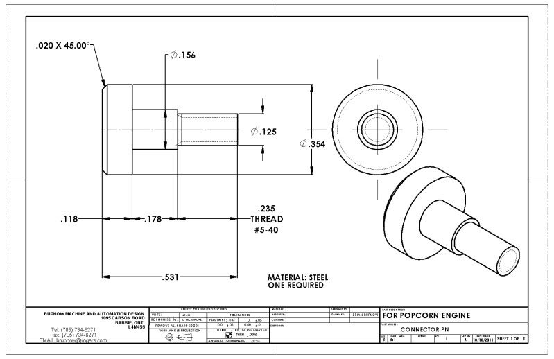
The pin that connects the piston rod to the connecting rod.
Design Engineer
Project of the Month Winner
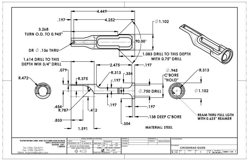
The crosshead guide. I haven't made it yet, but it certainly looks like its going to be interesting!!!
Design Engineer
Project of the Month Winner
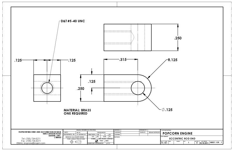
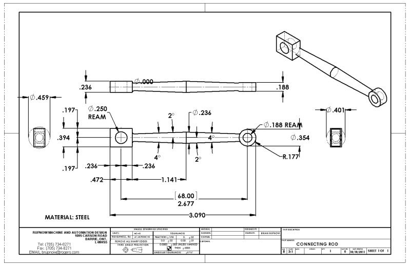
The connecting rod. This was the first tapered con rod I have ever made, and it was far easier than I thought it would be. Stew Hart shows how it was done in his Popcorn thread.