Brass Globe Valves

Home Model Engine Machinist Forum

Help Support Home Model Engine Machinist Forum:

This site may earn a commission from merchant affiliate links, including eBay, Amazon, and others.

Captain Jerry

Project of the Month Winner!!!
Project of the Month Winner
Joined
Dec 2, 2008
Messages
971
Reaction score
9
I just got in from the shop. All day to make two little globe valves. One is 180 degrees and the other is 90 degrees. Like this:


globevalveB043.jpg


I took some pictures and I will try to organize them for a post tonight.

Jerry

 
And very nice they are :bow: :bow: (one for each)

Best Regards
Bob
 
Very nice!

Hope along with the pictures you give us some detail on how you built them.
 
For sure, you cannot show us pics of something that nice without telling us how you went about making them. What will they be used on?
 
Cap'n, Very pretty - looking forward to the post.

Any chance of drawings ??

Ken
 

I took some pictures and I will try to organize them for a post tonight.

Jerry


..........uh um! ::) ;D


Jerry, you never cease to amaze me. Well done :bow: :bow:


Ron
 
Thanks for all the interest. Sorry the post did not happen. I forgot it was Friday (Pizza and beer!) and I fell asleep on the couch after dinner and woke up just in time to go to bed. I will try to get to it over the weekend.

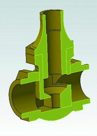
There may be a slight revision. The valve seat and porting on the valve with straight through flow and the handle on the side (I think that is the 180° style but I may be confused) is a little bit fiddly and a better method occurred to me in my sleep. I am off to the shop to try it out. Here is the model I'm working with.

globevalveagain.jpg


If it works out, drawings will follow.

Jerry
 
Lew

I sealed this one with Locktite (Red). The bottom of the insert is flat and the bore was finished with an endmill for a flat seat for the insert. I don't plan on using this for steam so Locktite will do just fine. I have tested this with 85PSI Air with good results. In the following video, the regulator is providing 85 PSI air to the top of the valve and the valve provides very fine control of engine speed and power.


Troutsqueezer

This is how I plan to use them. Every engine from here on out will include a globe valve for control. The final few posts on Stew Hart's (Potty Engineering) popcorn engine convinced me of the cosmetic value of proper plumbing to dress up an engine and I decided that was what I needed to do to complete the two overcrank engines that I built a few months ago. I whacked together some ugly over sized valves and installed them on the engines.

I was impressed with the control that they provided and horrified at their appearance. There were some recent posts about the PM Research valves and fittings and I remembered a thread that George Britnell posted a few years ago about his globe valves. I looked up George's thread and followed his design (mostly). I made some changes to accommodate my skills and equipment and it produced a much more presentable valve. Globe valves come in two style, 90° with the valve stem in the end and 180° with the valve stem on the side. George's design covered only the 90° style but there are places where the 180° fits better so I looked into how to build it. This is where I am now. Some refinements to be made to make small batch production easier.

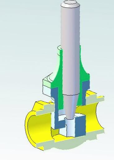
I posted a section view of a 3D model this morning and revised that today in the shop. The revision changes the conical valve seat (drilled) to a flat seat which required making a D-bit tool. The revision makes it easier to cut the in and out ports without intersecting the seat. The valve stem has a steep taper but is not so sharp that it should be called a needle valve.

GlobeValveSectionRevB-1.jpg


If all goes well tomorrow, I will try a 4 unit batch and try to do a proper step by step.

Jerry
 
That's very neat Jerry the 180 deg type are harder to design than the 90 deg as you need that little bit inside to close the flow, another way is to have that bit comming in from the bottom that way you have more head room to fit a sealing gland around the stem.

Speaking of a gland how did you manage to seal the stem, did you get a good enough fit to reduce leakage ?.

Stew
 
Stew

The stem is a #4-40 thread. The gray part in the model represents the max thread diameter. The stem cap, shown in green, is threaded for its full length which is .410" which is about 16 threads which seems to provide a good seal without a gland. The stem cap is threaded #10-32 into the seat insert and that connection is only 4 or 5 threads deep. It shows some leaking but that can be sealed with a paper gasket or sealant.

George's design used a #1-80 screw thread and he provided a non-threaded section of the stem with an #4-40 threaded gland nut at the top but it was not clear if he actually used any packing around the stem. I decided to go with a #4 screw for the the strength of the connection of the stem to the knob. I was afraid that it would be too easy to strip the threads in the knob with a thread that small. I don't mean to criticize George's design. I'm just explaining why I did it this way. Taps, dies and screw for anything smaller than #4-40 are expensive for the very limited use I would have for them.

Jerry

 
Great write up so far Jerry. I think this valve would well for compressed air

I would caution the use with steam as you can remove the stem while under pressure....steam valves usually have a stem that is retained so that can't happen.....it's less of an issue with low pressure compressed air though....especially in the smaller sizes we generally deal with.

Dave
 
I got started on building a 4 unit batch of valves. Due to some small interruptions, some poor planning, some easily avoided mistakes, I didn't get as far as I should have. I am going to salve my self esteem and ease my pain by reporting the positive result of the days effort. Here are 5 valve bodies, mostly complete and ready for the valve seat inserts:

badexperience012.jpg


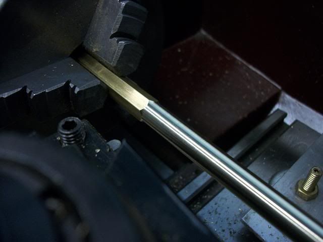
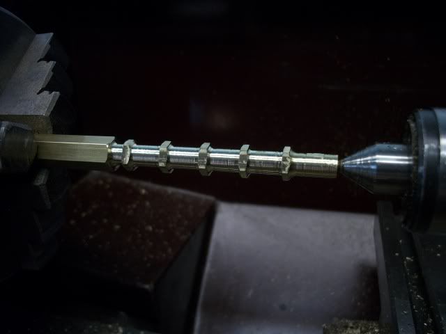
Starting out with a piece of 3/8" brass hex, one end of it was center drilled and then drilled and tapped for #10-32tpi. I then used a large center drill to put a chamfer in the end of the bore so that it could be supported on the live center without buggering the threads. I then extended it out of the chuck about 7 inches, supported the outboard end with the live center and turned it to a diameter of .375" for a length of about 6".

badexperience002.jpg


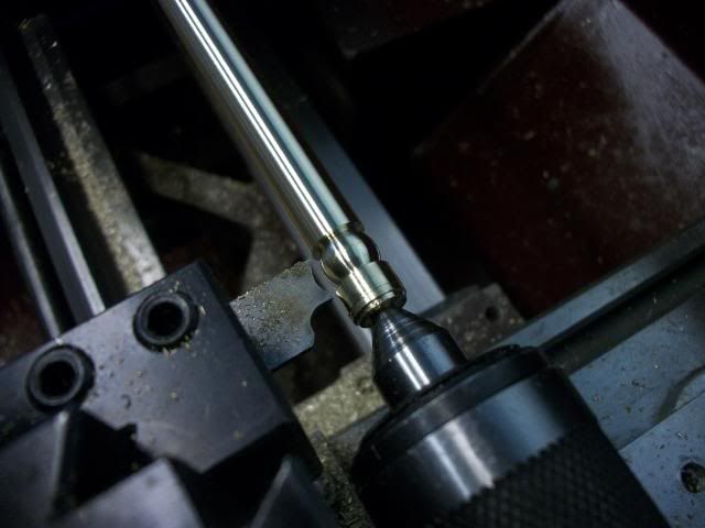
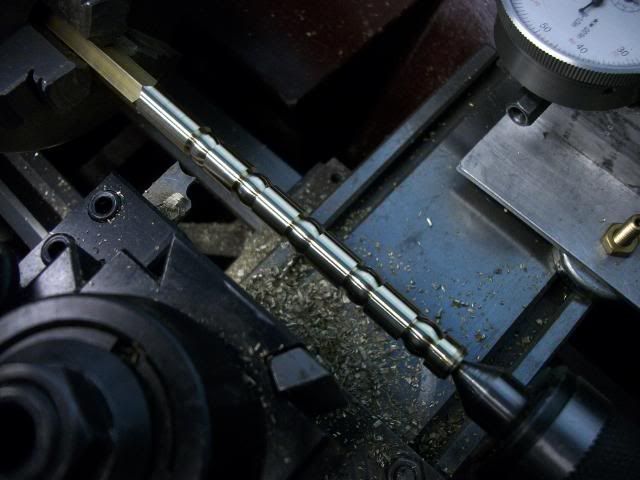
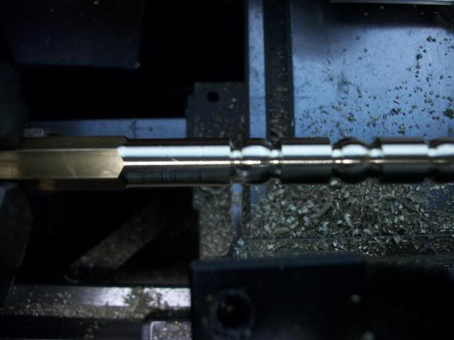
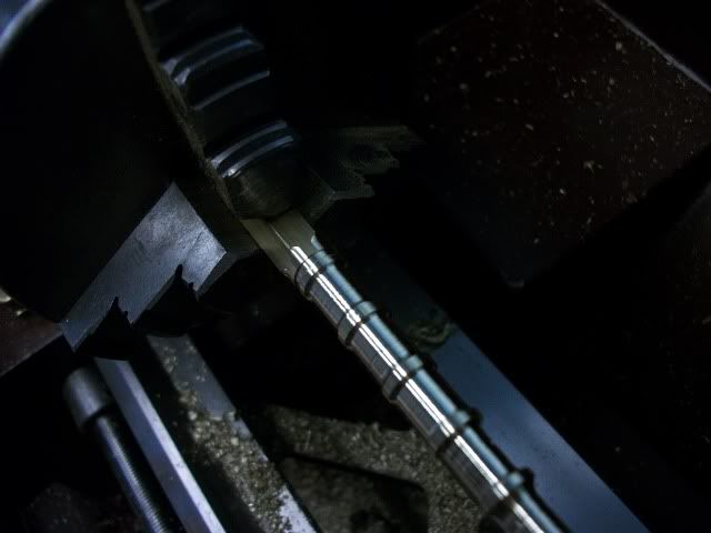
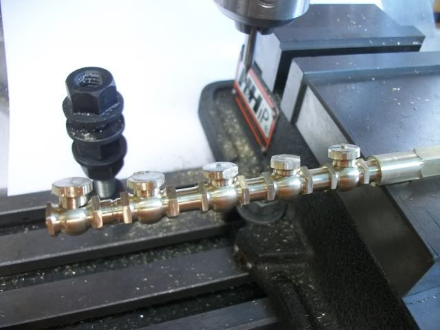
Then a form tool was used to form 5 globes. The radius of the form tool curve is .5" and is plunged in to the depth that leaves the center of the globe is left a full 3/8" diameter. This means that the globe is not a true sphere but I think the proportions are proper or at least pleasing.

badexperience005.jpg

badexperience006.jpg


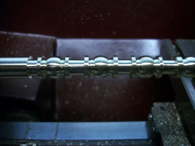
It is hard to see in the photo but the form tool provides only the .5" radius and does not include the return curve that blends into the hex flanges. I did this for a few reasons. Mainly it was to reduce the width of the form tool and make the plunge easier. It also means that a single tool could be used to form the return curves so that the radius is identical. That second form tool is shown in the cut in the next photo but it gets lost in the clutter.

badexperience008.jpg


The next step is to use a parting tool to form the outer face of the flanges and bring the bar to a diameter of .25" between valve bodies.

badexperience009.jpg


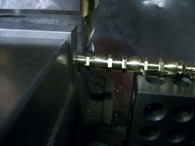
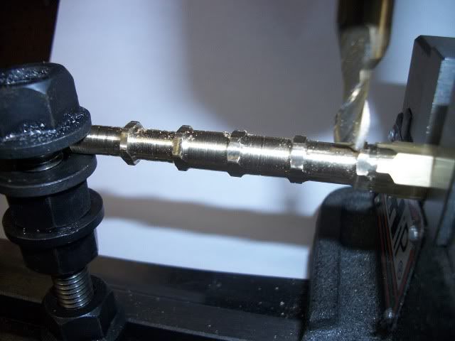
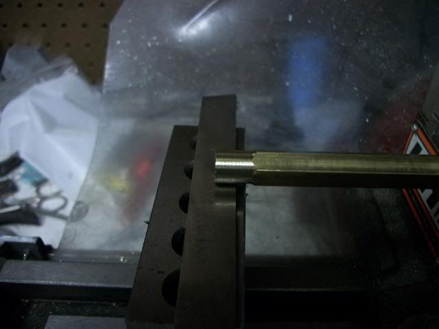
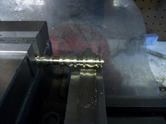
The flanges will be reduced to 5/16" in a later step on the mill. I wish I could claim to have thought of this in advance but it did not occur to me until I tried to set it up in the mill vice to drill for the valve seat inserts. The insert should line up with the apex of the hex, not the flat and the dimension across the corners is about .412". When the flats are gripped between the vise jaws, with one apex resting on the base, it was difficult to be sure that the outboard end was packed correctly to keep the bar level. The answer was to return the bar to the lathe and turn a shoulder on the opposite end to the same .375" diameter. The two ends of the bar could be then be supported at equal height ( 2.0625") and use the vice jaws only to hold the flats vertical.
badexperience011.jpg


badexperience010.jpg


The next step is fairly critical. The hole for the insert must be flat bottomed ( 1/4" 2 flute end mill) and it must be deep enough to clear the #10-32 tpi threads but not so deep as to exit through the sides of the globe. This works out to bring the bottom of the hole to a distance of .074" above the bottom of the globe so I brought the tip of the mill down to touch the packing under the globe, raised it .074" and set the depth stop. I then used this depth stop to limit the depth as I drilled each of the five holes. I did this without a pilot hole. The end mill is stiff enough and the hole is shallow enough that I did not worry about the hole wandering. I did not want to worry about changing tools and resetting the depth for each of the holes. I did worry about table shift as the bit touched the surface so I was careful to lock the X-axis at each position.

The Y-axis was located by locating each of the vise jaw faces and centering between them. The X position was located by centering it between my left eye and my right eye with an offset for parallax error and windage.

The reason that the first 1" of the bar was drilled and tapped at the beginning of this process was to provide a visual confirmation that the hole depth did in fact clear the threads so that the bottom of the insert will sit flush on the bottom for sealing.

The next step was to remove the 1/16" parting tool packing on the top of the 1-2-3 blocks and reposition the bar in the vise so that the flat of the hex was resting on the bottom of the vise ways and clamping on the opposite corners. The depth was set by touching the end mill on the upper flat and then lowering it by .0315". The resulting cut will reduce the flanges, which are now .375" round to 5/16" across the flats as the bar is indexed on the hex and the tool is traversed in the Y direction across the flanges. The outer end of the bar must be clamped down on a 1-2-3 block and care must be takes not to hit the globes with the tool.

badexperience012.jpg


badexperience019.jpg


Each of the valve bodies must now be drilled through and tapped #10-32. Since I can only tap a depth of about 1", each piece must be processed and then parted of to gain access to the next one. I will then be ready to produce 5 seat inserts and five caps and stems.

This has been a long windy post. Longer to write than to make the parts. If some step is unclear or if you want more information, just ask and I will try to clarify. Dimensions will be provided on the drawings I will post on completion.

Thanks for watching. More to come. 590

Jerry
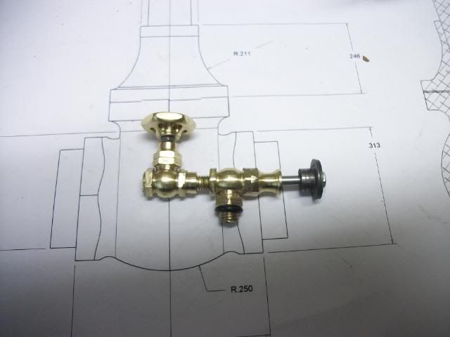
 
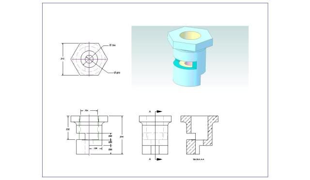
Here is a revised view of the valve. I realized last night that the orientation of the flats on the flanges was shown incorrectly in the previous illustrations. This is a 3D PDF that you can rotate and view from different angles if viewed with Adobe 9.4 or later. When you open the file, "Click to activate" lets you rotate it.

Jerry

View attachment globe valve revC.pdf
 
Captain Jerry said:
I just got in from the shop. All day to make two little globe valves. One is 180 degrees and the other is 90 degrees. Like this:


globevalveB043.jpg


I took some pictures and I will try to organize them for a post tonight.

Jerry

Marvelous work.
Can You show how You made that very nice hand wheel?
Cheers,Ralph
 
Ralph

Thanks for the compliment. Yes I will show the handwheel at the end of this thread, after the valve stem.

Today's project was to build five valve inserts to go with the valve bodies from yesterday. I have come to understand that it is much harder to build 5 pieces at one time than it is to build 5 pieces one at a time. There are new problems of part holding and order of operations that I was not prepared for. I went down a wrong path yesterday resulting in wasted material. But the time was not wasted. I learned from my mistake and made much better progress today.

Here is the part that I need (times 5):

globevalveinsert.jpg


I got started by turning 4 inches of a piece of 3/8" hex brass down to 3/8" round. It was supported on the outboard end with a live center.

The part will be .375" long and with an allowance of .0625" parting allowance and a bit more for finish, the part repeat distance is .460" so using my lathe DRO caliper, I marked off 5 sections, and leaving .0625" (flange thickness) standing proud, I turned the bar to a diameter of 5/16" which will be the distance across the flats after the hex is milled on the flanges.

SeatInsert002.jpg


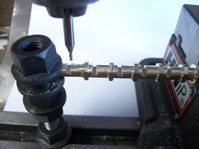
This next step might make some of you cringe. I removed the bar from the lathe chuck! I know about loss of concentricity but these are plumbing fixtures! I did mark the flat that sits on jaw #1 and the outer end is on the live center so it won't be far off when it goes back to the lathe. I then moved it over to the mill vise and set one of the flats on the vise ways with the outboard end supported and clamped. The bar was brought level by jacking with the lower nut. When I was satisfied that it was level, the nut below that was used to jamb the lower nut and then the top nut was clamped on.

SeatInsert005.jpg


The diameter between the flanges is 5/16" and was used to set the end mill height and the flats milled by traversing along the length of the bar. The bar was then indexed to the next flat in the vise and this was repeated until I had all six flats milled.

The problems that I had yesterday were caused by leaving this step until after I had turned the body to 1/4" diameter and then milled the valve ports. This so weakened the bar that when I got around to milling the flats ( using a less secure clamping arrangement ) bad things and bad words occurred. I felt much better today when I realized it was just a lesson.

Now the bar goes back to the lathe and the part was turned to final contour.

SeatInsert011.jpg


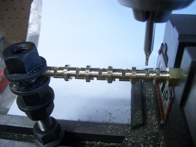
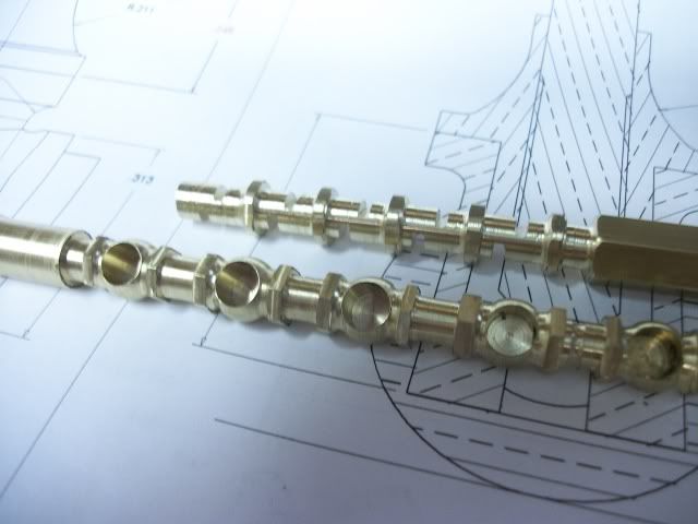
Then back to the mill where the valve port slots (1/16") were milled. The bottom port is milled to the center of the 1/4" body and the upper port is only half as deep. It intersects a larger bore in the valve cavity.

SeatInsert017.jpg


SeatInsert018.jpg


Not that the hex bar is gripped on the flats with one apex of the hex up. This is so the flats on the insert align with the flats on the valve body. When the bar is gripped this way. the center is raised so the outboard jack screw/clamp must be adjusted.

Then it is back to the lathe, where it is touched up with a fine file to remove the burrs raised by milling the slots. Each part was then parted from the bar. For some reason, I failed to record the parting off but it was carried out close to the chuck jaws and was uneventful.

SeatInsert020.jpg


SeatInsert025.jpg


Now the inserts must be drilled and tapped for the valve stem cap and the valve seats must be faced BUT!
My camera batteries died and it was getting close to supper time so I cleaned up and went home.

Thanks for watching. More tomorrow. 786

Jerry


Now that is just down right slick Jerry. I've always done valves individually from castings or purchased them, but now, seeing your method sure gives me renewed hope. ;D Now I just have to track down that pice of 3/8" hex I stashed away for safe keeping *somewhere* :-\

BC1
Jim
 
Jerry: This is a great series. Would it be possible to post you final drawings in the download section. I would like to try your techniques.

Thanks Bob
 
Back
Top