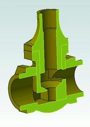
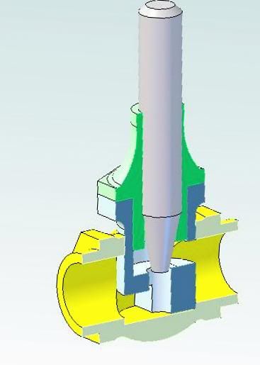
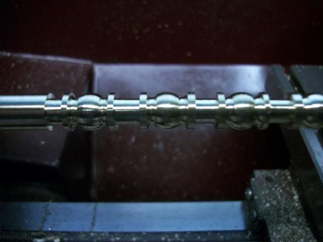
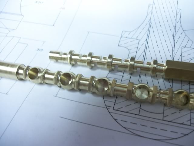
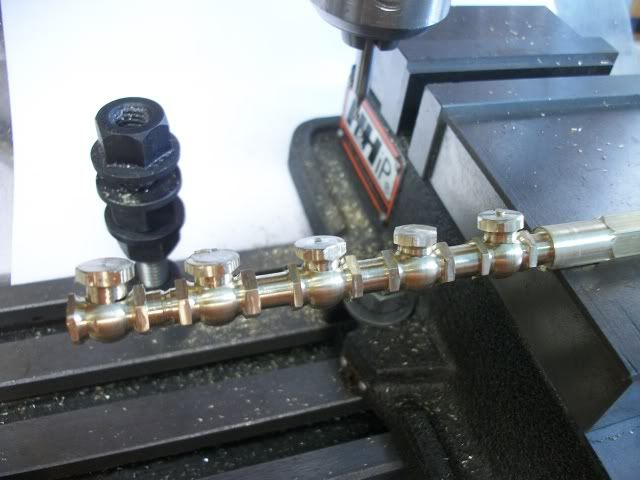
I got started on building a 4 unit batch of valves. Due to some small interruptions, some poor planning, some easily avoided mistakes, I didn't get as far as I should have. I am going to salve my self esteem and ease my pain by reporting the positive result of the days effort. Here are 5 valve bodies, mostly complete and ready for the valve seat inserts:
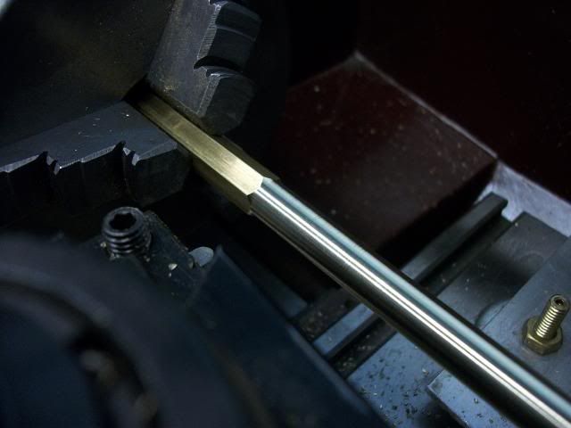
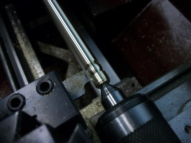
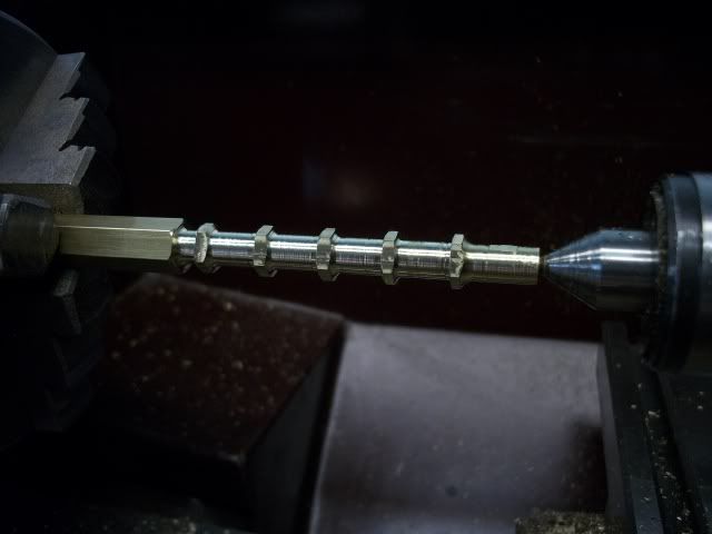
Starting out with a piece of 3/8" brass hex, one end of it was center drilled and then drilled and tapped for #10-32tpi. I then used a large center drill to put a chamfer in the end of the bore so that it could be supported on the live center without buggering the threads. I then extended it out of the chuck about 7 inches, supported the outboard end with the live center and turned it to a diameter of .375" for a length of about 6".
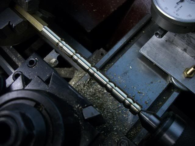
Then a form tool was used to form 5 globes. The radius of the form tool curve is .5" and is plunged in to the depth that leaves the center of the globe is left a full 3/8" diameter. This means that the globe is not a true sphere but I think the proportions are proper or at least pleasing.
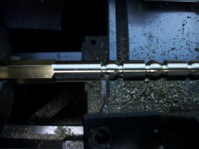
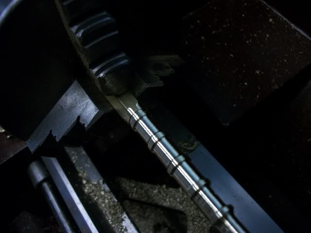
It is hard to see in the photo but the form tool provides only the .5" radius and does not include the return curve that blends into the hex flanges. I did this for a few reasons. Mainly it was to reduce the width of the form tool and make the plunge easier. It also means that a single tool could be used to form the return curves so that the radius is identical. That second form tool is shown in the cut in the next photo but it gets lost in the clutter.
The next step is to use a parting tool to form the outer face of the flanges and bring the bar to a diameter of .25" between valve bodies.
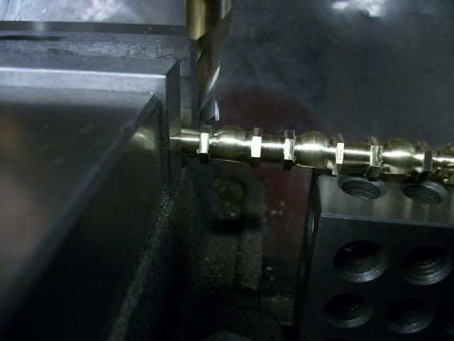
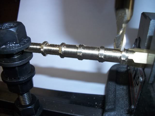
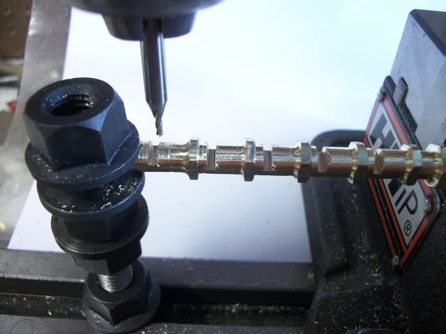
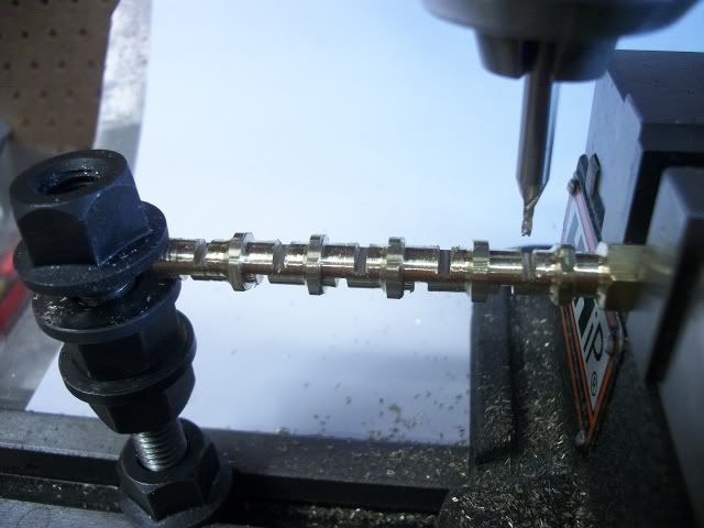
The flanges will be reduced to 5/16" in a later step on the mill. I wish I could claim to have thought of this in advance but it did not occur to me until I tried to set it up in the mill vice to drill for the valve seat inserts. The insert should line up with the apex of the hex, not the flat and the dimension across the corners is about .412". When the flats are gripped between the vise jaws, with one apex resting on the base, it was difficult to be sure that the outboard end was packed correctly to keep the bar level. The answer was to return the bar to the lathe and turn a shoulder on the opposite end to the same .375" diameter. The two ends of the bar could be then be supported at equal height ( 2.0625") and use the vice jaws only to hold the flats vertical.
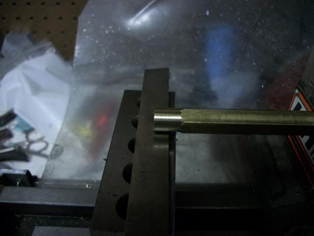
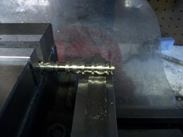
The next step is fairly critical. The hole for the insert must be flat bottomed ( 1/4" 2 flute end mill) and it must be deep enough to clear the #10-32 tpi threads but not so deep as to exit through the sides of the globe. This works out to bring the bottom of the hole to a distance of .074" above the bottom of the globe so I brought the tip of the mill down to touch the packing under the globe, raised it .074" and set the depth stop. I then used this depth stop to limit the depth as I drilled each of the five holes. I did this without a pilot hole. The end mill is stiff enough and the hole is shallow enough that I did not worry about the hole wandering. I did not want to worry about changing tools and resetting the depth for each of the holes. I did worry about table shift as the bit touched the surface so I was careful to lock the X-axis at each position.
The Y-axis was located by locating each of the vise jaw faces and centering between them. The X position was located by centering it between my left eye and my right eye with an offset for parallax error and windage.
The reason that the first 1" of the bar was drilled and tapped at the beginning of this process was to provide a visual confirmation that the hole depth did in fact clear the threads so that the bottom of the insert will sit flush on the bottom for sealing.
The next step was to remove the 1/16" parting tool packing on the top of the 1-2-3 blocks and reposition the bar in the vise so that the flat of the hex was resting on the bottom of the vise ways and clamping on the opposite corners. The depth was set by touching the end mill on the upper flat and then lowering it by .0315". The resulting cut will reduce the flanges, which are now .375" round to 5/16" across the flats as the bar is indexed on the hex and the tool is traversed in the Y direction across the flanges. The outer end of the bar must be clamped down on a 1-2-3 block and care must be takes not to hit the globes with the tool.
Each of the valve bodies must now be drilled through and tapped #10-32. Since I can only tap a depth of about 1", each piece must be processed and then parted of to gain access to the next one. I will then be ready to produce 5 seat inserts and five caps and stems.
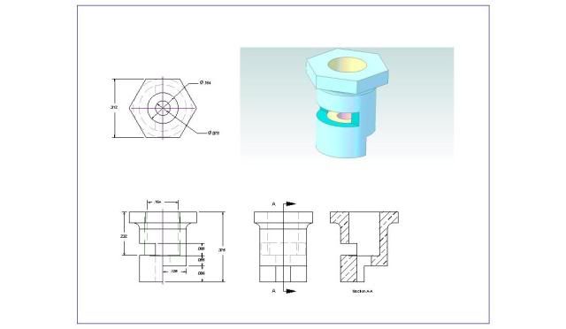
This has been a long windy post. Longer to write than to make the parts. If some step is unclear or if you want more information, just ask and I will try to clarify. Dimensions will be provided on the drawings I will post on completion.
Thanks for watching. More to come. 590
Jerry


![MeshMagic 3D Free 3D Modeling Software [Download]](https://m.media-amazon.com/images/I/B1U+p8ewjGS._SL500_.png)


